

Page 1

Instructions for use and installation
Cooker Hood
GB
Page 2

EN
3
3
Instructions Manual
INDEX
RECOMMENDATIONS AND SUGGESTIONS....................................................................................................................14
CHARACTERISTICS............................................................................................................................................................15
INSTALLATION....................................................................................................................................................................16
USE.......................................................................................................................................................................................19
MAINTENANCE ...................................................................................................................................................................20
Page 3
EN
1
14
RECOMMENDATIONS AND SUGGESTIONS
INSTALLATION
• The manufacturer will not be held liable for any damages resulting
from incorrect or improper installation.
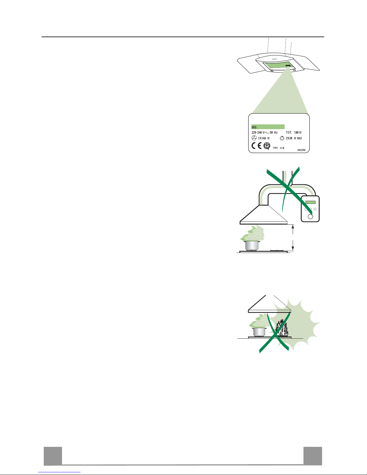
• The minimum safety distance between the c ooker top and the extractor hood is 650 mm.
• Check that the mains voltage corresponds to that indicated on the
rating plate fixed to the inside of the hood.
• For Class I appl ianc es, c heck t hat th e domes tic po wer suppl y gua rantees adequate earthing.
Connect the extractor t o the exhaust flue through a pipe of minimum
diameter 120 mm. The route of the flue must be as short as possible.
• Do not connect the extractor ho od to exhaust ducts carrying comb ustion fumes (boilers, fireplaces, etc.).
• If the extractor is used in conjunction with non-electrical appliances
(e.g. gas burning appliances), a suffi cient degree of aeration must be
guaranteed in the room in order to prevent the backflow of exhaust
gas. The kitchen must h ave an opening communicating di rectly with
the open air in order to guarantee the entry of clean air.
USE
• The extractor hood has been des igned exclusively for domesti c us e to
eliminate kitchen smells.
• Never use the hood for purposes other than for whi ch it has ben designed.
• Never leave high naked flames under the hood when it is in operation.
• Adjust the flame intensity to direct it onto the bottom of the pan only,
making sure that it does not engulf the sides.
• Deep fat fryers must be continuously monitored during use: overheated oil can burst into flames.
• The hood should not be used by chil dren or persons not ins tructed in
its correct use.
MAINTENANCE
• Switch off or unplug the appliance from the mains supply before carrying out any maintenance work.
• Clean and/or replace the Filters after the specified time period.
• Clean the hood using a damp cloth and a neutral liquid detergent.
650 mm min.
Page 4

EN
1
15
CHARACTERISTICS
Dimensions
300
490
265
254
107.5
150
545
80
598 / 898
ø150
ø120
51
70
572
min. 730
max. 1000
650 min.
253
63
4181
126
Components
Ref. Q.ty Product Components
1 1 Hood Body, complete with: Controls, Light, Blower,
Filters
2 1 Telescopic Chimney comprising:
2.1 1 Upper Section
2.2 1 Lower Section
9 1 Reducer Flange ø 150- 120 mm
14.1 2 Air Outlet C onnection Extension
15 1 Air Outlet Connection
Ref. Q.ty Installation Components
7.2.1 2 Upper Chimney Section Fixing Brackets
7.3 1 Air Outlet Connection Support
11 6 Wall Plugs
12a 6 Screws 4,2 x 44,4
12c 6 Screws 2,9 x 9,5
Q.ty Documentation
1 Instruction Manual
2.1
2.2
2
12c
12a
7.2.1 11
11
12a
9
7.3
14.1
15
1
1
Page 5

EN
1
16
INSTALLATION
Wall drilling and bracket fixing
Wall marking:
• Draw a vertical line on the supporting wall up to the ceiling, or as high as practical, at the
centre of the area in which the hood will be installed.
• Draw a horizontal line at 650 mm above the hob.
• Place bracket 7.2.1 on the wall as shown about 1-2 mm from the ceiling or upper limit align-
ing the centre (notch) with the vertical reference line.
• Mark the wall at the centres of the holes in the bracket.
• Place bracket 7.2.1 on the wall as shown at X mm below the first bracket (X = height of the
upper chimney section supplied), aligning the centre (notch) with the vertical line.
• Mark the wall at the centres of the holes in the bracket.
• Mark a reference point as indicated at 116 mm from the vertical reference line and 310 mm
above the horizontal reference line.
• Repeat this operation on the other side.
• Drill ø 8 mm holes at all the centre points marked.
• Insert the wall plugs 11 in the holes.
• Fix the lower bracket 7.2.1 using the 12a screws (4,2 x 44,4) supplied.
• Fix the upper bracket 7.2.1 and the air outlet connection support 7.3 together using the 2
screws 12a (4,2 x 44,4) supplied.
• Insert the two screws 12a (4,2 x 44,4) supplied in the hood body fixing holes, leaving a gap
of 5-6 mm between the wall and the head of the screw.
11
12a
310
X
116
1÷2
116
650 min.
7.2.1
Page 6

EN
1
17
Mounting the hood body
• Before attaching the hood body, tighten the two screws Vr located on the hood body mounting points.
• Hook the hood body onto the screws 12a.
• Fully tighten support screws 12a.
• Adjust screws Vr to level the hood body.
12a
Vr
Connections
DUCTED VERSION AIR EXHAUST SYSTEM
When installing the ducted version, connect the hood to the
chimney using either a flexible or rigid pipe ø 150 or 120 mm,
the choice of which is left to the installer.
• To install a ø 120 mm air exhaust connection, insert the reducer flange 9 on the hood body outlet.
• Fix the pipe in position using sufficient pipe clamps (not supplied).
• Remove any activated charcoal filters.
9
ø 120ø 150
RECIRCULATION VERSION AIR OUTLET
• Put connection 15 into the connection support 7.3.
• Insert the connection extension pieces laterally 14.1 in connection 15.
• Make sure that the outlet of the extension pieces 14.1 is horizontally and vertically aligned with the chimney outlets.
• Connect the air outlet connection 15 to the hood body outlet
using either a flexible or rigid pipe ø 150 mm, the choice of
which is left to the installer.
• Ensure that the activated charcoal filters have been inserted.
ø 150
14.1
15
Page 7

EN
1
18
ELECTRICAL CONNECTION
• Connect the hood to the mains through a two-pole
switch having a contact gap of at least 3 mm.
• Remove the grease filters (see paragraph Maintenance) being sure that the connector of the feeding
cable is correctly inserted in the socket placed on the
side of the fan.
Flue assembly
Upper exhaust flue
• Slightly widen the two sides of the upper flue and
hook them behind the brackets 7.2.1, making sure
that they are well seated.
• Secure the sides to the brackets using the 4 screws
12c (2,9 x 9,5) supplied.
• Make sure that the outlet of the extensions pieces is
aligned with the chimney outlets.
Lower exhaust flue
• Slightly widen the two sides of the flue and hook
them between the upper flue and the wall,
making sure that they are well seated.
• Fix the lower part laterally to the hood body using
the 2 screws 12c (2,9 x 9,5) supplied.
12c
12c
12c
2.1
2.2
2
7.2.1
Page 8

EN
1
19
USE
S
V1V1V1V1V1V1V1V1V1V1V1V1V1V1V1V1V1V1
V2
V3
L
L Light Switches the lighting system on and off.
S Led Motor running led.
V1 Motor Switches the extractor motor on and off at low speed. Used to provide a
contin-uos and silent air change in the presence of light cooking vapours.
V2 Speed Medium speed, suitable for most operating conditions given the optimum
treated air flox/noise level ratio.
V3 Intensive Maximum speed, used for eliminating the highest cooking vapour emission,
including long periods.
Page 9

EN
2
20
MAINTENANCE
Grease filters
CLEANING METAL SELF- S U PPORTING GREASE FILTERS
• The filters must be cleaned every 2 months of operation, or more frequently for particularly heavy
usage, and can be washed in a dishwasher.
• Remove the filters one at a time by pushing them
towards the back of the group and pulling down at
the same time.
• Wash the filters, taking care not to bend them. Allow them to dry before refitting.
• When refitting the filters, make sure that the handle is visible on the outside.
Activated charcoal filter (Recirculation version)
REPLACING THE ACTIVA TED CHARCOAL FILTER
• The filter is not washable and cannot be regenerated, and must be replaced approximately every 4
months of operation, or more frequently for particularly heavy usage.
• Remove the metal grease filters
• Remove the saturated activated carbon filter by
releasing the fixing hooks
• Fit the new filter by hooking it into its seating
• Replace the metal grease filters.
Lighting
LIGHT REPLACEMENT
20 W halogen light.
• Remove the snap-on lamp cover by levering it from
under the metal ring, supporting it with one hand.
• Remove the halogen lamp from the lamp holder by
pulling gently.
• Replace the lamp with a new one of the same type,
making sure that you insert the two pins properly into
the housings on the lamp holder.
• Replace the snap-on lamp cover.
Page 10

436002823_ver3
Il simbolo sul prodotto o sulla co nfezi on e indi ca che il prodo tto no n d eve ess ere c ons id era to co me un n ormal e r ifi uto dom es tic o,
ma deve ess ere port ato n el p unto di rac c olta appro pri ato p er i l r icic laggi o di appar ec chi atur e el ettri ch e ed el ettr onic he. P rov v ede ndo a
smaltire q ues to pro d otto i n m odo a ppro pri ato, s i contri bui sce a evi tar e p otenz ial i co nse gue nze nega tiv e per l ’am bi ente e per la s alute,
che potrebb er o derivare da un o s m al ti m e nto inadegu ato del prodotto. Per inf or m azioni più de tt agliate sul r i c i c l aggi o di questo prodotto,
contattare l’u ff icio comunale, il servizio locale di smaltimento rifiuti o il negozio in cui è stato acquistato il prodotto.
The symbol on the product or on its pac kaging indic a tes t ha t thi s pr o duct may not be tr e at ed as househol d w as t e. Instead it s hal l
be handed ov er to the applicable c ollectio n point for the recyc ling of elec trical and electroni c equipm ent. By ensur ing this product is
disposed of correctly, you will help prevent potential negative consequences for the environment and human health, which could otherwise be caus ed by in appr opr iat e wast e han dli ng of this pro duct. F or mor e detai led infor mati o n about recyc li ng of this pro duct , ple ase
contact your local city office, your household waste disposal service or the shop where you purchased the product.
Le symbole sur le produit ou son em bal la ge in diqu e que c e pr od uit ne peut ê tre tr aité c omm e déc he t mén ager . Il d oit pl utôt être
remis au point de ramassage concerné, se chargeant du recyclage du matériel électrique et électronique. En vous assurant que ce
produit est él imi né correc temen t, vous favori sez l a préventi on des conséq uenc es nég atives p our l’ environ neme nt et la sa nté hum aine
qui, sinon, s er ai e nt l e r ésultat d’un tr ai t em ent inappropr i é d es d éc h ets d e c e produit. Pour o bt e nir plus de détai l s s ur l e recyclage de ce
produit, veuillez prendre contact avec le bureau municipal de votre région, votre service d’élimination des déchets ménagers ou le
magasin où vo us av ez acheté le produi t.
Das Symbol auf dem Prod ukt oder seiner Verp acku ng weis t darauf hin, das s di eses Pro dukt n icht al s norm aler H aushalts abfal l
zu behandel n i st, s on der n an ein em S am melp unk t f ür das R ecy cli ng v on el ek tri sche n un d el ek troni sc hen G erä te n ab geg ebe n wer de n
muss. Durc h Ihren Beitra g zum korrek te n Entsorgen dieses Prod uk ts s chützen Si e die Umwelt un d die Gesund h ei t Ihrer Mitme ns chen.
Umwelt und Gesundheit werden durch falsches Entsorgen gefährdet. Weitere Informationen über das Recycling dieses Produkts
erhalten Sie von Ihrem Rathaus, Ihrer Müllabfuhr oder dem Geschäft, in dem Sie das Produkt gekauft haben.
Ürün veya pak eti üzerindeki sembolü, bu ürünün normal bir ev sel atık olarak gör ülmemesi ve bu tip elek trikli veya elektr onik
cihazları n atıldı ğı dönüşüm lü topl ama n oktal arına t erke dilm esi ger ektiğine işaret e der. B u ürünü g erekti ği gibi elim ine etm e kural ların a
uyarsanız çevre ve insan sağlığı üzerindeki olum suz etkilerini b ertaraf etmeye katk ı sağlamış olursunuz. B u ürünün geri d önüşüm
koşulları hakkında daha ayrıntılı bilgi için hudutları içinde bulunduğunuz belediyenin ilgili diaresine, atık yoketme servisine veya ürünün
satıcısına da nışınız.
Franke S.p.a.
Via Pignolini,2
37019 Peschiera del Garda (VR)
www.franke.it
73/23/CEE
Dir. 89/336/CEE
93/68/CEE
 Loading...