

Page 1
1
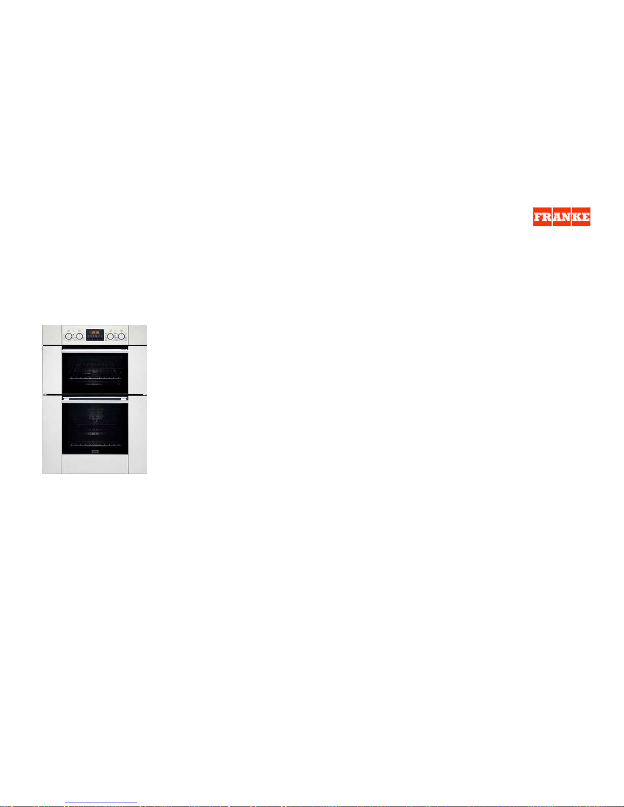
HANDBOOK BUILT-IN MULTIFUNCTION DOUBLE OVE AX937 DXA
UPDATED FEBRUARY 2007
CONTENTS:
Technical data page 2
TOP oven programme selector knob page 3
Cooking modes bottom oven page 4
Cooking modes top oven page 6
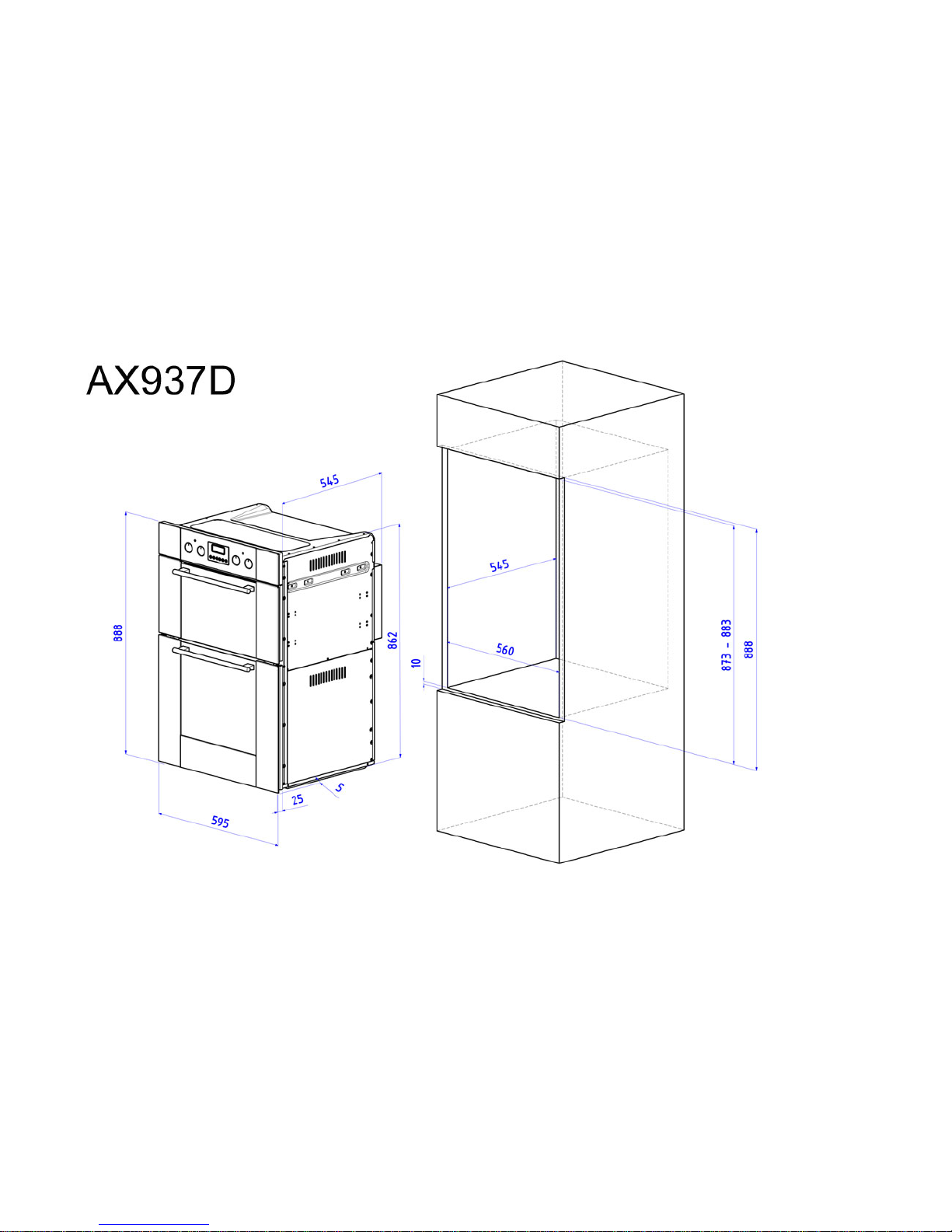
Drawing page 7
Installation page 8
Replacing the oven lamps page 9
Electronic cooking programmer page 10
Failures and error codes electronic programmer page 13
Cooking modes display –preheat page 13
Clearing programs page 14
Standby mode page 14
General connection page 15
List spare parts page 16
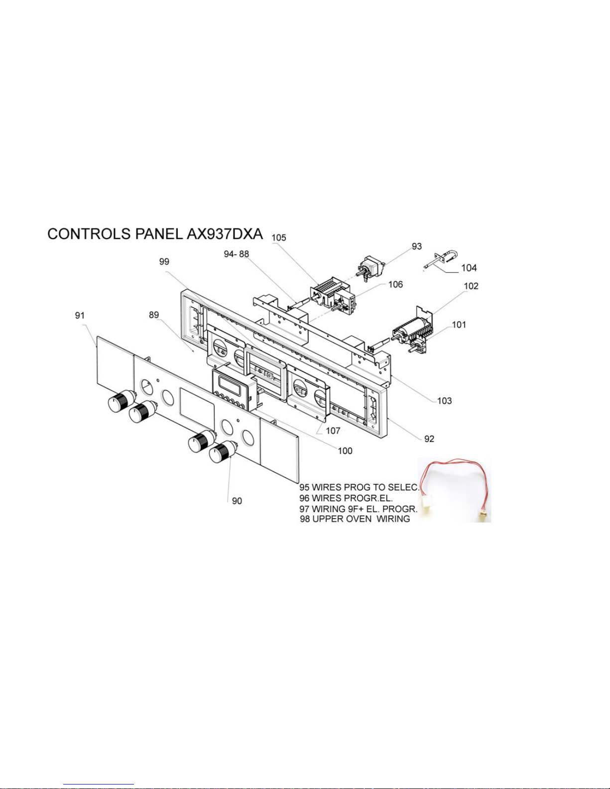
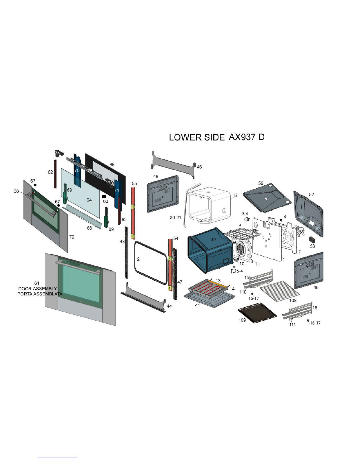
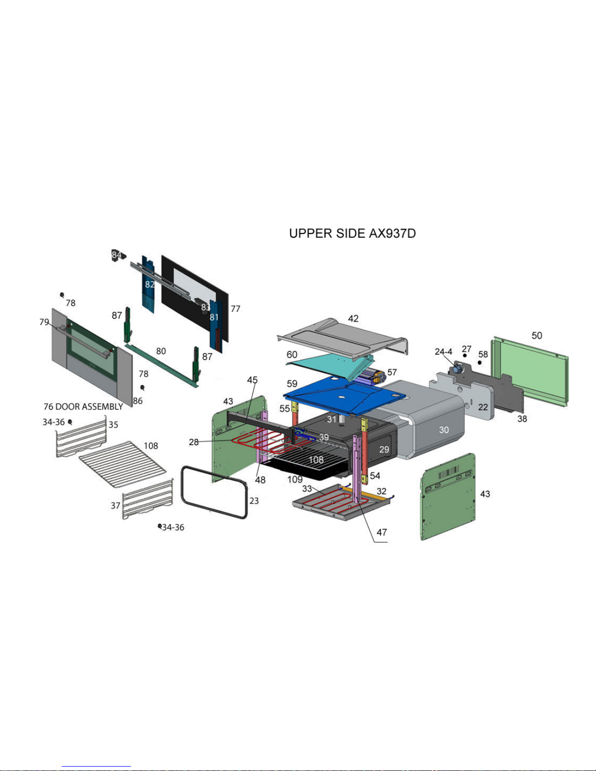
Esploded view page 20
Controls panel 20
Lower side ax937 d 21
Upper side ax937d 22
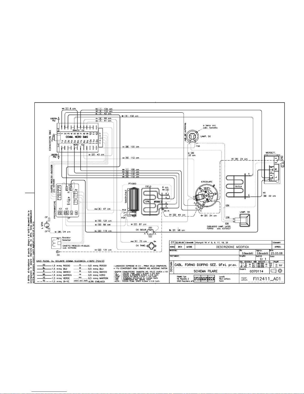
WIRING DIAGRAM 23
Page 2

2
Technical data
Top oven useful dimensions:
width 420 mm
depth 415 mm
height 188 mm
Bottom oven useful dimensions:
width 440 mm
depth 415 mm
height 312 mm
Top oven useful volume:
34 litres
Bottom oven useful volume:
57 litres
Top oven consumption
(static operation):
to reach 175°C: 0.30 kWh
to maintain 175°C: 0.41 kWh
total consumption: 0.71 kWh
Bottom oven consumption
(static operation):
to reach 175°C: 0.30 kWh
to maintain 175°C: 0.41 kWh
total consumption: 0.71 kWh
Bottom oven consumption
(fan operation):
to reach 200°C: 0.31 kWh
to maintain 200°C: 0.81 kWh
total consumption: 1.12 kWh
Power supply voltage and
frequency:
230V ~ 50Hz
Total max. power and fuse capacity:
5.145 kW - 24A
Heating element power: roof 1000 W
top oven floor W 800
bottom oven floor W 1250
grill 2250 W
fan 30 W
oven light 1 x 15 W
tangential fan 15 W
Page 3
3
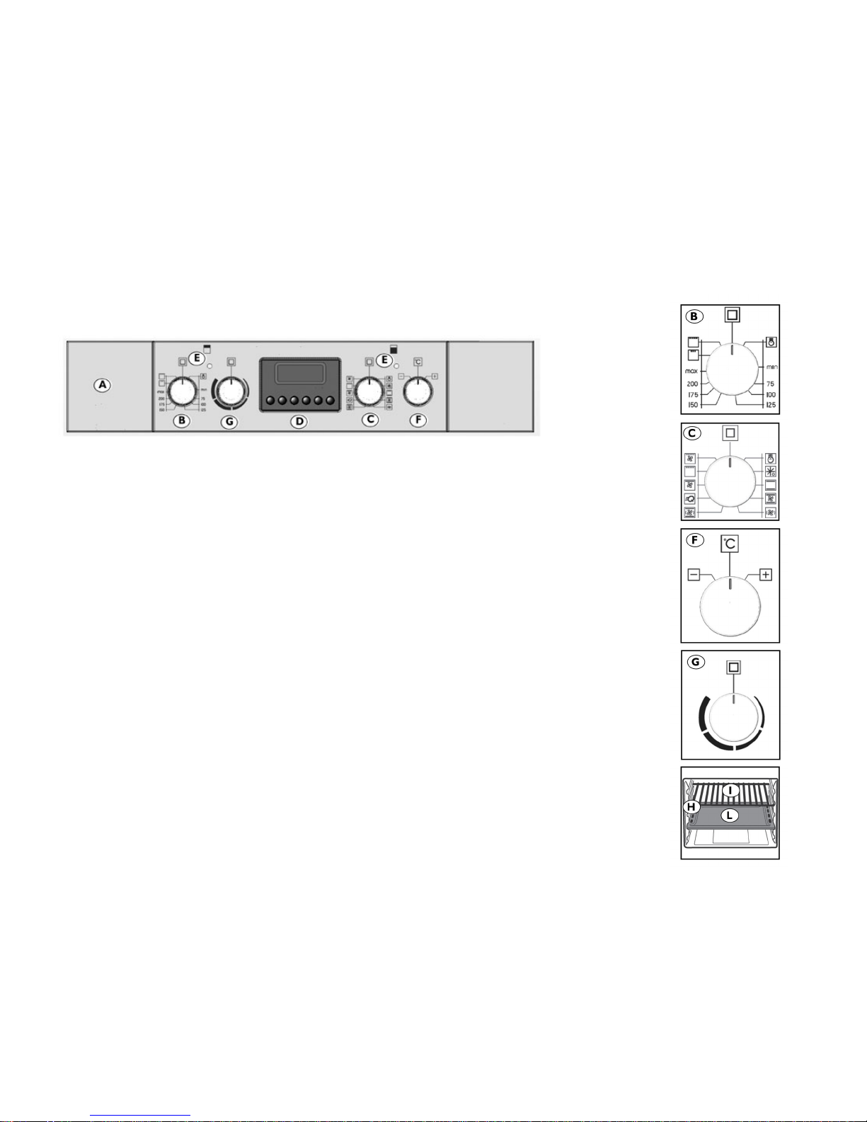
Top oven programme selector knob
B For selecting the oven mode according to the type of cooking required. When the knob is set to any programme, the
oven light comes on indicating that the oven is switched on. The set temperature only refers to the static operation
mode.
C Bottom oven programme selector knob
For selecting the oven mode according to the type of cooking requ ired. When the knob is set to any programme, the
oven light comes on indicating that the oven is switched on.
D ProgrammerOn page you can find the instructions relevant to its use.
E Thermostat light
Shown by the symbol C it signals that the oven electrical heating elements are activated. It goes off when the set
temperature has been reached, and comes on again whenever oven heating is switched on again. It is for useful
checking if the temperature has been reached, before introducing the food.
F Bottom oven temperature control knob
(Thermostat)
Used to set the temperature required for the type of food being cooked, keeping it constant during cooking. To select the
required temperature, turn the knob clockwise, bringing the pointer to the corresponding number. Max. temperature is
approx. 260°C.
G Top oven power adjustment
Used to set the temperature required for the type of food being cooked, keeping it constant during cooking. To select the
required temperature,turn the knob clockwise, bringing the pointer to the corresponding number. Max. temperature is
approx. 260°C.
H Grill and drip-tray runners
Used for correctly positioning the grills and drip-trays in 3 set positions (top oven) or 5 set positions (bottom oven) (from
1 to 3 or 5 starting from the bottom); the cooking table (page 9) indicates which position gives best results for each type
of cooking.
I Drip-tray
Normally used for collecting juices from grilled food or for cooking food directly; the drip-tray must be removed from the
oven if not used. The drip-trays are made from “AA” type enamelled steel for food use.
Page 4
4
L Grill Used for supporting pans, pastry moulds, and any containers other than the drip-trays provided, or for cooking mainly wiwith the meat and
fish grill
and grill + fan functions, toasting bread, etc.
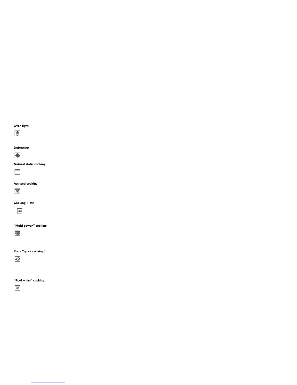
Oven light
This symbol corresponds to switching on of the oven light without activation of any type of heating. This option is useful for
cleaning the oven when it is switched off, to see the cooking compartment.
Bottom oven cooking programmes
Defrosting
Set the knob to the symbol () to obtain the defrost function.
In this case, the fan inside the oven circulates air around the food, speeding up the natural
thawing process.
Natural static cooking
Set the thermostat knob (F) between 50°C and Max. (260°C).
The heat source is above the food (roof heating element) and below it (floor heating element). This is the traditional cooking
function which ensures even cooking using a single rack.
Assisted cooking
Set the thermostat knob (E) between 50°C and Max. (260°C).
This turns on the top (roof) heating element, the bottom (floor) heating element and the fan inside the oven; compared with the
previous function (static cooking) the fan distributes the heat more evenly, so that two racks can be used at the same time.
Cooking + fan
Set the thermostat knob (F) between 50°C and Max. (260°C).
This turns on the top (roof) heating element, the bottom (floor) heating element and the fan inside the oven.
The constant and even heat cooks and browns the food evenly. Various dishes can be cooked at the same time, using a
maximum of 2 racks.
"Multi power" cooking + fan
Set the thermostat knob (E) between 50°C and Max. (260°C).
This turns on the circular heating element together with partial activation of the top (roof) and bottom (floor) heating elements and
the fan. Compared with the previous function, it is a more powerful and faster way to reach the required temperature; this, in
combination with an even temperature distribution, makes it ideal for meat and fish roasts and for baked pasta, using up to three
racks.
Pizza "quick cooking"
Set the thermostat knob (E) between 50°C and Max. (260°C).This turns on the circular heating element together with top (roof)
and bottom (floor) heating elements and fan. This is the most powerful function available on your Franke oven, and the heat
Page 5
5
istribution is designed to be more intense towards the bottom; this makes it ideal for preparing pizzas or fast cooking of frozen foods in general. It
can be used for quickly bringing the oven to the required temperature, and then setting any of the other available programmes.
"Roof + fan" cooking
Set the thermostat knob (E) between 50°C and Max. (260°C).
The top (roof) heating element and the fan are activated. The low power of this function and the fan allow very gentle and even cooking. Ideal for
dry pastry and certain types of baked pasta.
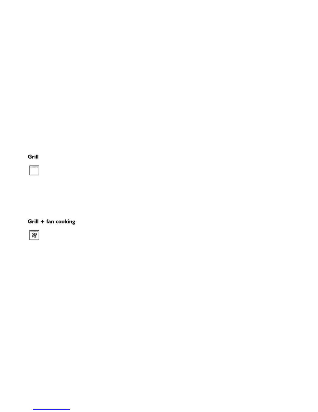
Grill
The thermostat knob (F) should normally be set to Max. (260°C), however a lower temperature can be set, in
which case grilling will be slower.
The grill heating element at the top of the oven switches on. In this case the fast infrared surface cooking keeps
the meat tender on the inside; the grill can also be used for quickly toasting up to 9 slices of bread. The Franke
oven is designed to grill food with the oven door completely closed.
Warning: The grill heating element becomes very hot during use; take care not to touch it accidentally when
handling the food to be grilled; in any case, Franke has designed the oven opening to protect hands as much as
possible.
Grill + fan cooking
The thermostat knob (F) should normally be set to Max. (260°C), however a lower temperature can be set, in
which case grilling will be slower.
The grill heating element at the top of the oven and the fan are activated. It combines oneway heat radiation with
forced air circulation inside the oven. This prevents burning the surface of the food and increases penetration of
the heat. Excellent results are obtained using the grill + fan for mixed meat and vegetable kebabs, sausages,
spare-ribs and lamb chops, broiled chicken, quail with sage, pork fillets, etc.
Page 6

6
Top oven cooking programmes
Natural static cooking
Set the power knob (G) between Min. and Max. (260°C).
The heat source is above the food (roof heating element) and below it (floor heating element). This is the traditional cooking
function which ensures even cooking using a single rack.
Light grill cooking
To activate this function, set the power with the knob (G). It is used for browning by lightly grilling or warming already cooked
food.
Full grill cooking
The power knob (G) should normally be set to Max. (260°C), however a lower temperature can be set, in which case grilling will
be slower.
The grill heating element at the top of the oven switches on. In this case the fast infrared surface cooking keeps the meat tender
on the inside; the grill can also be used for quickly toasting up to 9 slices of bread. The Franke oven is designed to grill food with
the oven door completely closed.
Warning: The grill heating element becomes very hot during use; take care not to touch it accidentally when handling the food to
be grilled; in any case, Franke has designed the oven opening to protect hands as much as possible.
Page 7
7
Page 8
8
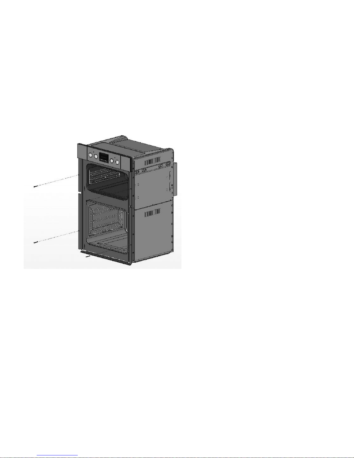
Fit the appliance in the compartment; fix the oven to the cabinet with the 4 screws provided, using the holes prepared in the side panels.
Cabinet requirements
For built-in units, the components (plastic materials and veneered wood) must be assembled with heat-resistant adhesives (max.100°C):
unsuitable materials and adhesives can result in warpingand ungluing. The cabinet must allow sufficient room for the electrical connections. The
cabinet in which the oven in fitted must be strong enough to take the weight of the equipment.
The oven must be securely installed in the recess. The oven can be installed in a column cabinet, provided sufficient ventilation is guaranteed.
Page 9
9
Replacing the oven lamps
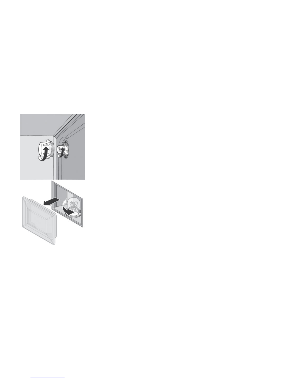
Franke ovens are equipped with a rectangular side lamps and 2 circular rear lamps.
Replace the oven lamp as follows:
- switch off the power to the appliance at the omnipolar switch used for connecting it to
the electrical system, or disconnect the plug, if accessible;
Rear ring lamp:
- Unscrew the glass cover (A)
- unscrew the lamp and replace with one resistant to high temperatures (300°C), having
the following characteristics:
Voltage: 220/230V - 50Hz
Power: 15W
Fitting: (E14) small
Side lamp
- remove the glass cover (B), prising it off with a flat screwdriver,
unscrew the lamp and replace it with one resistant to high temperatures (300°C),
having the following characteristics:
Voltage: 220/230V - 50Hz
Power: 15W
Fitting: (E14) small
Page 10
10
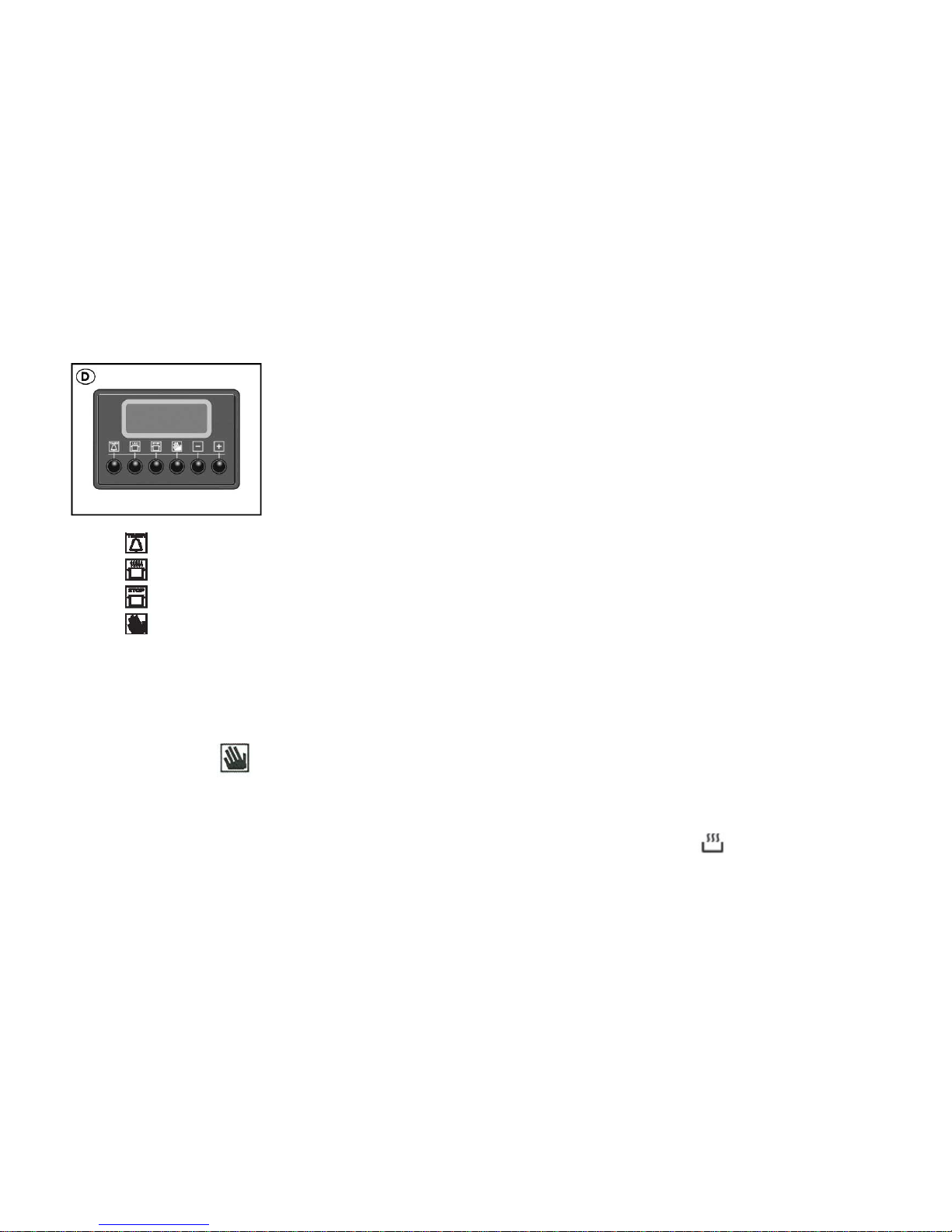
ADVANCED Electronic cooking programmer with bottom oven temperature control
Used for programming the bottom oven or its grill in the following mod es :
• delayed start of cooking with set time;
• immediate start of cooking with set time;
• timer.
•
•
•
•
•
• Button functions:
hours, minutes timer
cooking duration
end of cooking
manual switching
- : time setting (back)
- + time setting (forwards)
-
How to set the digital clock
After the appliance has been connected to the power supply, or when the power has gone out, the clock display will automatically reset to
0:00 and begin to blink. 0.00
• Press the
button and then set the correct time (within four seconds) using the [—] and [+]buttons.
Button + sets the time forward.
Button - sets the time backward.
For possible clock adjustments, repeat the steps described above:
Oven manual operation
When a cooking programme is selected, the oven immediately starts heating up, as indicated by the symbol on the display.
For each programme, a recommended cooking temperature is shown on the display ; this temperature can be changed by the user with
the knob : turn anticlockwise to decrease the temperature, or clockwise to increase it.
Page 11
11
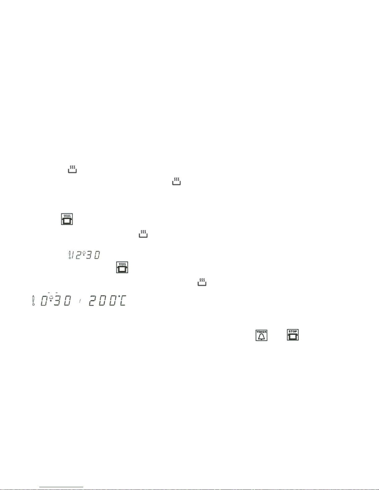
The flashing symbol
on the display indicates the preheating phase, during which the oven has not yet reached the required temperature. Once the set
temperature is reached, the oven beeps for two seconds and the symbol
stops flashing (steady) to indicate the cooking phase.
Immediate start of cooking with set time
Assuming cooking for 30 minutes at 200°C
Turn the programme selector knob; the display will show a recommended cooking temperature, which ca n be adjusted with the temperature C control knob.
Press the button
and then buttons [- ] and [+] to set the required cooking duration of 30 minutes.
Release the button; after 4 seconds the flashing symbol
indicates the preheating phase. The countdown starts only when the required temperature has
been reached (except for grill function, when the countdown starts immediately; see B). The display indications are as follows:
A - preheating phase
(the set time can be checked with the button
and the temperature with the buttons .- and + )
Once the set temperature is reached, the oven beeps for two seconds and the symbol
stops flashing (steady) to indicate the cooking phase.
B - cooking phase
(remaining cooking time / set temperature - alternating)
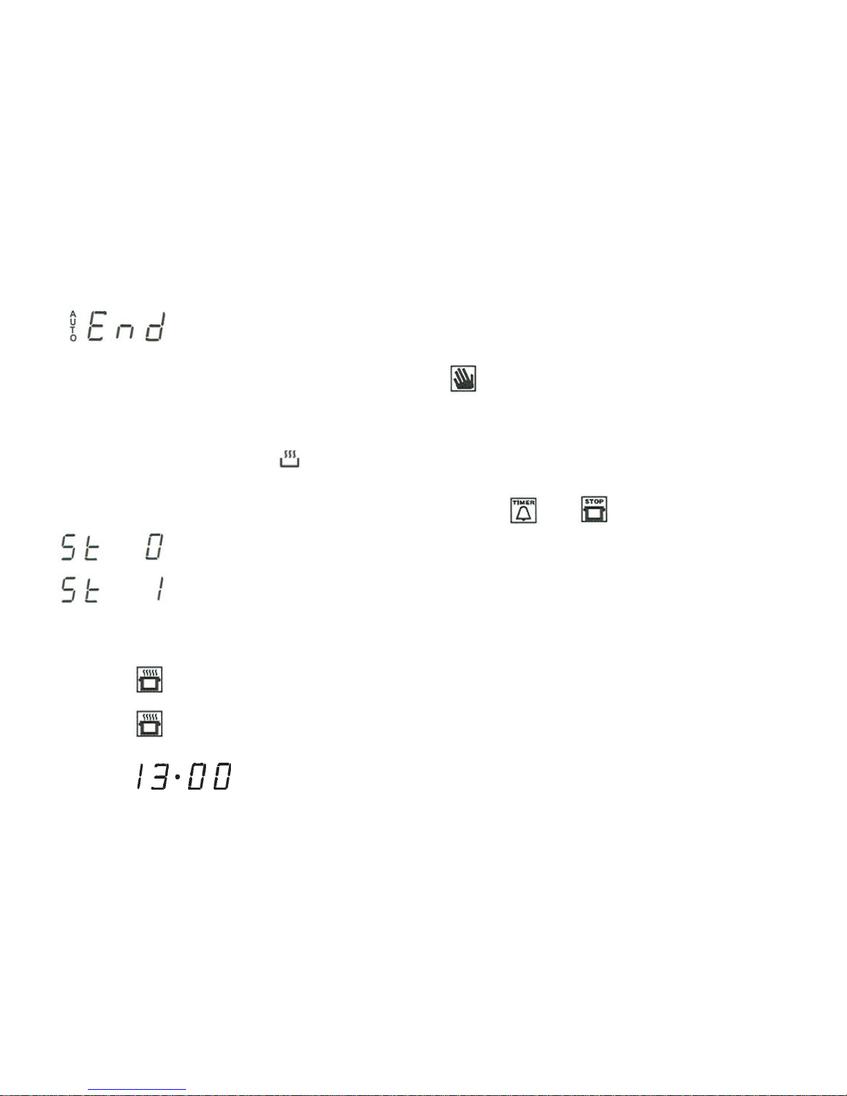
C - end of cooking
At the end of cooking an intermittent signal (**) will sound for 1 minute, which can be silenced with the button + ,
and stop ,; the display will show
the message
Page 12
12
The oven will automatically switch off the heating, the fans will stay on to prevent residual heat, and the lighting remains on for checking cooking. The
temperature may remain high for several minutes. To continue cooking manually, press
to reactivate heating.
The message AUTO disappears, and the symbol
will reappear. To stop everything, turn the programme selector knob to 0. For 3 seconds the display will
show
OFF
After which, the current time will be displayed (to dim the display with the oven off, press the buttons ,
and stop , and the following will appear:
with buttons [-] and [+] set this parameter to:
the display will go off and reactivates only when the oven is operating).
(**): the volume can be changed when the buzzer is on and for subsequent signalling, by pressing the button ----
Starting of delayed cooking with set time
Set the cooking duration and the end of cooking time. Assuming the time is 8:00 h and cooking is for 30 minutes ending at 13:00 h.
Turn the programme selector knob; the display will show a recommended cooking temperature, which can be adjusted with the temperatu re C control knob.
Press the button
and then buttons [-] and \+\ to set the required cooking duration of 30 minutes.
Press the button
and within 4 seconds with buttons [- ] and [+] set the required end of cooking time, i.e. 13:00 h.
The display will show:
AUTO
Page 13
13
The oven is now programmed and in standby.
To check the set duration press the button
; to adjust it operate the buttons - OR + .
To check the set temperature press a button [-] or + ; to adjust it operate the knob C .
Cooking phase:
On reaching the cooking phase the oven behaves as in point B of the previous paragraph.Except that the cooking duration countdown starts immediately, and not
after the required temperature has been reached. This is because the controller assumes that the food has alrea dy been placed in the oven at the moment of
programming. The preheating time is included in the cooking time.
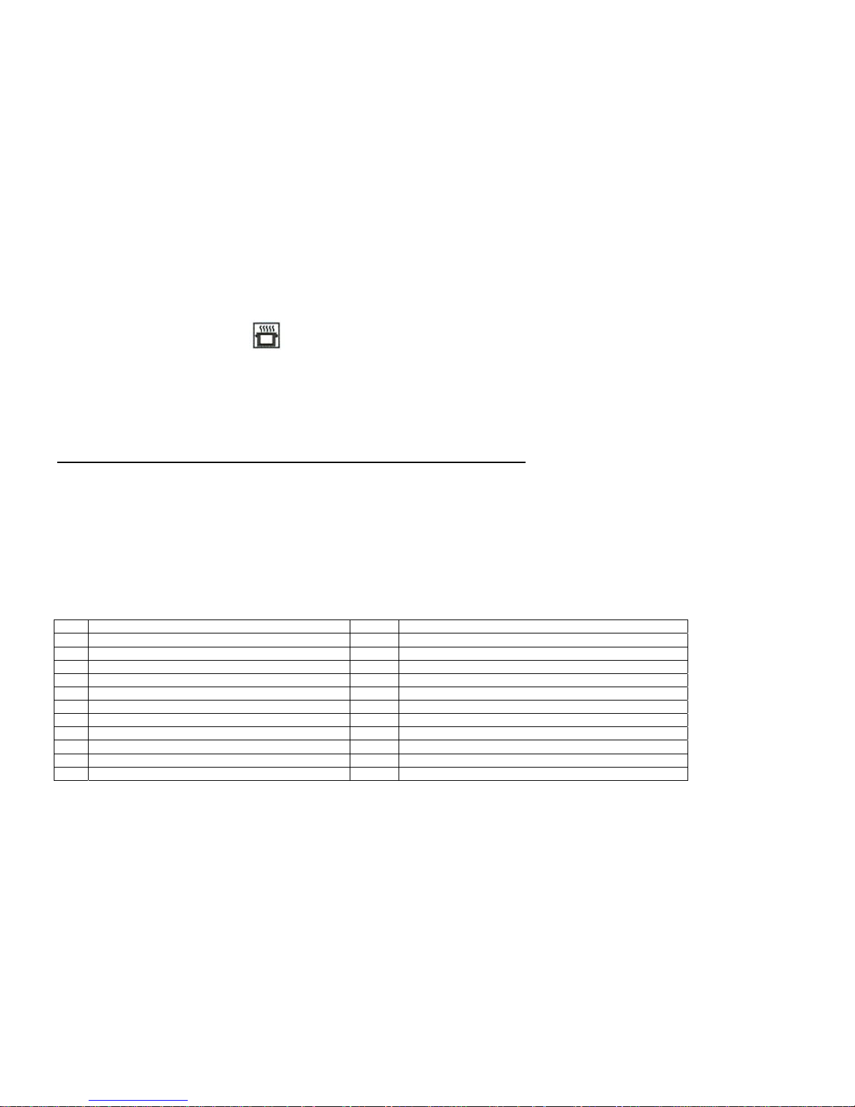
Failures and Error Codes ELECTRONIC PROGRAMMER ADVANCED
Whenever a failure is detected, a failure signal sounds and the display reads the belonging error code:
F3E3 Temp. sensor short circuit
F3E0 Temp. sensor open circuit
F4E0 EEPROM failure
At multiple errors, the display priority is as follows: F3E3, F3E0, F4E0.
The error message is automatically cleared when the failure is repaired. For EEPROM failure, the control has to be
reset first, for all other failures this can happen during program run.
At every failure, oven heating relay 1 is switched off.
Pos. COOKING Mode Display Preheat
0 Off hh:mm No
1 Light hh:mm No
2 Defrost dEF No
3 Bottom + Top Heat + Grill 180°C Yes
4 Bottom + Top Heat + Grill + Fan 180°C Yes
5 Ring Element + Fan 150°C Yes
6 Ring Element + Bottom + Top Heat + Grill + Fan 200°C Yes
7 Ring Element + Bottom Heat + Grill + Fan ("Fast") 220°C Yes
8 Grill + Top Heat + Fan 160°C No
9 Grill 220°C No
10 Grill + Fan 220°C No
Page 14

14
Clearing Programs
Program times for minute minder or automatic baking can be cleared by
"Clear Function”: Press PLUS and MINUS button simultaneously after selecting the program.
After this Clear the display returns from adjustment mode immediately.
Back counting of program duration to zero.
After a zero time value is reached, adjustment mode remains until time window has passed.
An automatic program is cleared by pressing MANUAL button
If the mode selector is turned to Off or to Light mode, an automatic program is cleared
Standby Mode
In Standby Mode, the display gets dark at Off or Light mode, if no minute minder program is active. In Standby Mode, whenever a key is pressed,
the display is illuminated until time window has run down. DURATION, END TIME, MINUS or PLUS button have no meaning in this case, so just
time of day is displayed.
Standby setting mode is entered by pressing together MINUTE MINDER and DURATION button. The display reads "St 0/1" with flashing 0 or 1,
where 0/1 means Standby off/on. So the display gets dark when St 1 is set. Set or reset Standby Mode by PLUS or MINUS in turns.
Page 15

15
GENERAL CONNECTION
FRANKE ovens are supplied with a three-core power cable with free terminals.
If the oven is permanently connected to the power supply, install a device that ensures disconnection from the power supply, with a contact
opening distance (at least 3 mm) enabling complete disconnection in category III overvoltage conditions. Make sure:
a) the plug and socket are suitable for a current of at least 24A
b) both can be easily reached and are positioned so that no live part is accessible when inserting or removing the plug
c) the plug can be easily inserted
d) when plugged in, the oven does not rest against the plug when installed in the cabinet
e) the terminals of two appliances are not connected to the same plug
f) a 3 x 2.5 mm
2 cable type H05VV-F must be used when replacing the power cable
g) the connection polarities of the free terminals must be respected
(Brown=Phase – Blue=Neutral – Yellow/Green=Earth)
NB: Make sure the characteristics of your household electrical system (voltage, maximum power and current) are compatible with those of your
FRANKE oven.
Page 16
16
ID_PRODOTTO SERVICE CODE DESCRIPTION QUANTITY POSITION TECHNICAL NUMBER IN TECHNICAL NOTE
5600243 1992004 HEATER HOLE INSULATOR 1 1
5600243 1992639 GASKET 1 2
5600243 1992006 OVEN LAMPHOLDER 2 3
5600243 1992096 LAMP 3 4
5600243 1992094 OVEN LAMP /RECTANGULAR LAMP HOLDER 1 5
5600243 1992007 THERMOSTAT SAFETY TY 280° 16A 1 6
5600243 1992060 OVEN BACK PANEL 1 7
5600243 1992205 ASSEMBLY FAN MOTOR 1 8
5600243 1992010 GRILL+TOP ELEMENT 2250+556 W 1 9
5600243 1992011 CIRCULAR FAN ELEMENT 2000W 1 10
5600243 1992012 FAN DIFFUSER 1 11
5600243 1992097 INSULATION CASING LAMP SIDE 1 12
5600243 1992014 OVEN LOW HEATING ELEMENT 1250 W 1 13
5600243 1992015 LOWER PANEL 1 14
5600243 1992016 WIRE RACKS SIDE LEFT 1 15
5600243 1992146 INSERT GRID LEFT ( NO 2 INSERT) 1 15
5600243 1992017 SUPPORT WIRE RACKS SIDE 2 16
5600243 1992147 INSERT GRID RIGHT ( NO 2 INSERT) 1 16
5600243 1992018 SCREW TSP M5X20 FIXING CASING 2 17
5600243 1992019 WIRE RACKS SIDE RIGHT 1 18
5600243 1992800 OVEN CUBE 1 19
5600243 1992801 SIDE CHIMNEY 1 20
5600243 1992802 HOSE SUPPORT 1 21
5600243 1992753 REAR INSULATOR FOR OVEN 1 22
5600243 1992770 GASKET 1 23
5600243 1992006 OVEN LAMPHOLDER 1 24
5600243 1992007 THERMOSTAT SAFETY TY 280°C 16A 1 27
5600243 1992010 GRILL+TOP ELEMENT 2250+556 W 1 28
5600243 1992752 OVEN CUBE LAMP REAR 1 29
5600243 1992593 INSULATION CASING 1 30
5600243 1992721 INTERNAL OVEN CHIMNEY 1 31
5600243 1992722 HEATING ELEMENT BOX 1 32
5600243 1992599 OVEN LOW HEATING ELEMENT 800 W 1 33
5600243 1992017 SUPPORT WIRE RACKS SDE 2 34
Page 17
17
5600243 1992595 WIRE RACK SIDE LEFT 1 35
5600243 1992018 SCREW TSP M5X20 2 36
5600243 1992594 WIRE RACK SIDE RIGHT 1 37
5600243 1992750 OVEN BACK PANEL 1 38
5600243 1992604 TOP DEFLECTOR FOR OVEN CUBE 1 39
5600243 1992023 TOP BULKHEAD CASING 1 41
5600243 1992025 OUTER CASING 1 42
5600243 1992608 SIDE PANEL RIGHT/LEFT 2 43
5600243 1992804 LOWER FRAME 1 44
5600243 1992805 UPPER FRAME 1 45
5600243 1992806 MIDDLE FRAME 1 46
5600243 1992807 EXTERNAL RIGHT SIDE 1 47
5600243 1992808 EXTERNAL LEFT SIDE 1 48
5600243 1992809 SIDE RIGHT/LEFT DOUBLE OVEN 2 49
5600243 1992810 REAR SUPPORT 1 50
5600243 1992549 REAR CASING 1 52
5600243 1992811 TERMINAL BLOCK 1 53
5600243 1992812 RIGHT SUPPOR HINGE OVEN DOOR 1 54
5600243 1992813 LEFT SUPPORT HINGE OVEN DOOR 1 55
5600243 1992814 AIR COVEYOR 1 56
5600243 1992059 FAN TANGENTIAL 1 SPEED 14 W 1 57
5600243 1992402 THERMOSTAT SAFETY TANGENTIAL FAN 80° C 2 58
5600243 1992815 LOWER AIR CONVEYOR 2 59
5600243 1992831 AIR CONVEYOR UPPER SIDE 1 60
5600243 1992716 DOOR ASSEMBLY AX97MXA 1 61
5600243 1992034 DOOR GASKET L 390 MM 2 62
5600243 1992031 OVEN DOOR GLASS SPACER 1 63
5600243 1992210 GLASS DOOR INTERMEDIATE 1 64
5600243 1992712 INTERNAL GLASS 1 65
5600243 1992560 OVEN DOOR LOWER TRIM AXIS 1 66
5600243 1992075 RUBBER WASHER NR 10 PCS 2 67
5600243 1992043 HANDLE 1 68
5600243 1992567 HINGE OVEN DOOR 2 69
5600243 1992561 POST DOOR GLASS LEFT 1 70
5600243 1992562 POST DOOR GLASS RIGHT 1 71
Page 18
18
5600243 1992713 GLASS DOOR+STAINLESS STEEL FRAME 1 72
5600243 1992563 RIGHT BRACKET HANDLE HONNER INNER 1 73
5600243 1992564 LEFT BRACKET HANDLE HONNER INNER 1 74
5600243 1992714 UPPER TRIM 1 75
5600243 1992817 DOOR ASSEMBLY UPPER OVEN 1 76
5600243 1992818 INTERNAL GLASS 1 77
5600243 1992075 RUBBER WASHER NR 10 PCS 2 78
5600243 1992043 HANDLE 1 79
5600243 1992819 OVEN PLINTH 1 80
5600243 1992820 UPPER RIGHT POST DOOR OVEN 1 81
5600243 1992821 UPPER LEFT POST DOOR OVEN 1 82
5600243 1992563 RIGHT BRACKET HANDLE HONNER INNER 1 83
5600243 1992564 LEFT BRACKET HANDLE HONNER INNER 1 84
5600243 1992714 UPPER TRIM 1 85
5600243 1992822 GLASS+STAINLES STEEL FRAME OVEN DOOR 1 86
5600243 1992787 HINGE OVEN DOOR LITTLE OVEN 2 87
5600243 1992046 NEON LIGHT COVER 1 88
5600243 1992243 KNOB SUPPORT 4 89
5600243 1992134 KNOB PUSH PULL 4 90
5600243 1992823 CONTROLS PANEL AX937DXA 1 91
5600243 1992619 SUPPORT CONTROL PANEL 1 92
5600243 1992051 THERMOSTAT 1 BULB 1 93
5600243 1992061 PILOT LAMP 2 94
5600243 1992139 WIRES PROGRAMMER EL TO SELECTOR 1 95
5600243 1992138 WIRES PROGRAMMER EL 1 96
5600243 1992824 WIRING 9F +EL.PROM. AX937DXA 1 97
5600243 1992825 UPPER WIRING AX937DXA 1 98
5600243 1992826 EL.PROM. SUPPORT 1 99
5600243 1992143 ELECTRONIC PROGRAMMER EVOLUTE 1 100
5600243 1992242 THERMOSTAT/BOARD RESISTOR SELECTOR 1 101
5600243 1992141 SELECTOR 12C 11P ENCODER 1 102
5600243 1992827 CONTROLS PANEL SUPPORT 1 103
5600243 1992828 PROBE PT1000 115 CM 1 104
5600243 1992829 SELECTOR 3F 1 105
5600243 1982312 ENERGY REGULATOR 1 106
Page 19
19
5600243 1992830 PUSH-PULL KNOB SUPPORT 2 107
5600243 1992055 OVEN RACK 2 108
5600243 1992056 DRIP TRAY BLACK 450X385 MM 2 109
5600243 1992144 TELESCOPIC ARMS LEFT 1 110
5600243 1992145 TELESCOPIC ARMS RIGHT 1 111
Page 20
20
Page 21
21
Page 22
22
Page 23
23
Page 24

24
Page 25

25
 Loading...