

Franke 2030019212, 2030019221, FAID0008, FAID0006 Installation And Operating Instructions Manual
DE
EN
PL
Installation and operating instructions Montaż i instrukcja obsługi
EA-Nr.: 7612982217180
FAR-Best.-Nr.: 2030019212
FAID0010
EA-Nr.: 7612982217210
FAR-Best.-Nr.: 2030019221
FAID0011
ZMI_001_2030019212-FAID0010_#SALL_#AQU_#V1.fm / 24.09.19

...................................................................................... 3
Please refer to the graphics in the German Installation and
Operating Instructions.
...................................................................................... 4
Prosimy przyjąć grafikę z niemieckiej instrukcji montażu i
obsługi.
EN
PL
Inhaltsverzeichnis11.fm
2

0English
EN
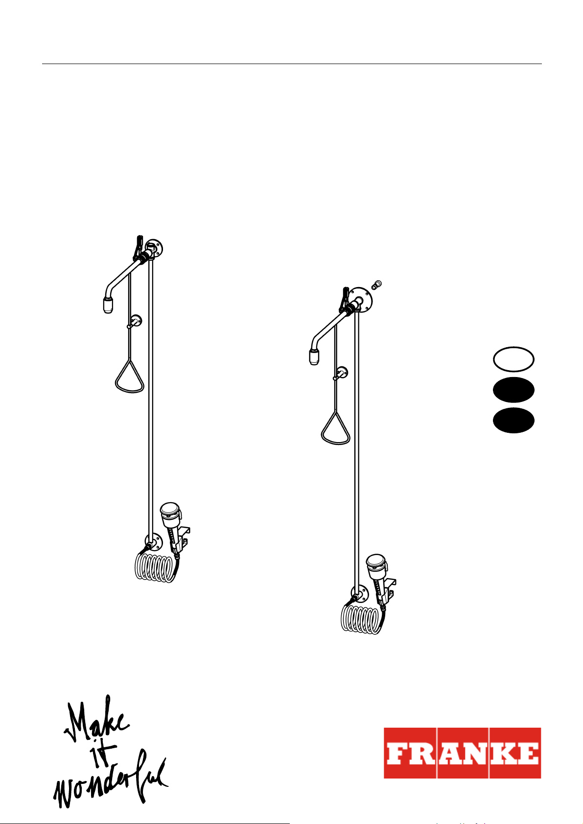
Emergency shower combination
Please refer to the graphics in the German installation and operating instructions.
0 Table of contents
1. Abbreviations and units . . . . . . . . . . . . . . . . . . . . . . . . . . . . . . . . 3
2. Key . . . . . . . . . . . . . . . . . . . . . . . . . . . . . . . . . . . . . . . . . . . . . . . . 3
3. Warranty . . . . . . . . . . . . . . . . . . . . . . . . . . . . . . . . . . . . . . . . . . . . 3
4. Important notes. . . . . . . . . . . . . . . . . . . . . . . . . . . . . . . . . . . . . . . 3
Description of product
5. Application . . . . . . . . . . . . . . . . . . . . . . . . . . . . . . . . . . . . . . . . . . 4
6. Technical specifications . . . . . . . . . . . . . . . . . . . . . . . . . . . . . . . . 4
7. Scope of delivery . . . . . . . . . . . . . . . . . . . . . . . . . . . . . . . . . . . . . 5
8. Dimensions. . . . . . . . . . . . . . . . . . . . . . . . . . . . . . . . . . . . . . . . . . 6
9. Installation example . . . . . . . . . . . . . . . . . . . . . . . . . . . . . . . . . . . 6
Assembly, function and commissioning
10. Installation of body shower water connection from above . . . . . . 7
11. Installation of body shower water connection from behind. . . . . . 11
12. Installation of eye shower . . . . . . . . . . . . . . . . . . . . . . . . . . . . . . . 16
13. Function . . . . . . . . . . . . . . . . . . . . . . . . . . . . . . . . . . . . . . . . . . . . 18
Maintenance
14. Maintenance and care . . . . . . . . . . . . . . . . . . . . . . . . . . . . . . . . . 19
15. Replacing a filter. . . . . . . . . . . . . . . . . . . . . . . . . . . . . . . . . . . . . . 19
16. Replacing the flow rate regulator . . . . . . . . . . . . . . . . . . . . . . . . . 20
17. Replacing the non-return valve. . . . . . . . . . . . . . . . . . . . . . . . . . . 21
18. Troubleshooting . . . . . . . . . . . . . . . . . . . . . . . . . . . . . . . . . . . . . . 21
19. Spare parts . . . . . . . . . . . . . . . . . . . . . . . . . . . . . . . . . . . . . . . . . . 22
1. Abbreviations and units
EA-Nr. European article number
FAR-Best.-Nr. Franke Aquarotter order number
Conversion 1 mm = 0.03937 inches
1 inch = 25.4 mm
All length specifications in the graphics are in mm.
ZMI_001_2030019212-FAID0010_#SEN_#AQU_#V1.fm
- 3 -

2. Key
Warning!
Failure to observe can result in bodily injury or even death.
Caution!
Failure to observe can result in material damage.
☞ Important!
Failure to observe can cause the product to malfunction.
☞ Useful information for optimum handling of the product.
3. Warranty
Liability is accepted in accordance with the General Terms and Conditions of
Business and Supply.
Use only genuine spare parts!
4. Important notes
• Installation, commissioning and maintenance must be performed only by a
qualified expert in accordance with the instructions provided, legal requirements
and recognised engineering standards.
• All technical connection regulations specified by the local water and electricity
supply companies must be observed.
• We reserve the right to make changes.
5. Application
Emergency showers are prescribed first aid installations for work stations where
hazardous materials are being handled.
- 4 -
ZMI_001_2030019212-FAID0010_#SEN_#AQU_#V1.fm

6. Technical specifications
Body shower
Minimum flow pressure: 0.5 bar
Maximum stagnation pressure: 10 bar
Volumetric flow:
0.5 bar flow pressure: 45 l/m
1.0 bar flow pressure: 65 l/m
1.5 bar flow pressure: 80 l/m
2.0 bar flow pressure: 90 l/m
2.5 bar flow pressure: 100 l/m
3.0 bar flow pressure: 110 l/m
Assembly height: Lower edge of shower head (220 ± 10) cm
above floor as per EN 15154 Part 1
Eye shower
Version: Hand shower plastic green/white
Wall mounting, tilted 20° forwards, spiral hose and
protective cap with user information
Minimum flow
pressure: 1 bar
Flow pressure range: 1-4 bar
This range meets the requirements of EN 15154.
Volumetric flow: Constant 6-9 l/s at a flow pressure of 1 bar
ZMI_001_2030019212-FAID0010_#SEN_#AQU_#V1.fm
- 5 -

7. Scope of delivery
Pos. Name 2030019212 2030019221
1 Shower head x x
2 Wall bracket x x
3 Ball valve x x
4 Wall plate with connecting pipe x
5 Wall plate with connecting pipe and plug-in
socket
x
6 Hand actuator with plugging option x x
7 Accessories kit:
First aid sign, screws and wall plug
xx
8 Eye shower with safety cap x x
9 Wall mounting with attachment set x x
10 Spiral supply hose with filter x x
11 First aid sign x x
Installation and operating instructions x x
8. Dimensions
For special designs, see the customer drawing for dimensions
9. Installation example
10. Installation of body shower water connection from above
☞ Important!
• Prior to the assembly process, flush the pipework in accordance with DIN 1988.
• Mount the emergency shower in accordance with EN 15154 Part 1.
☞ The manual actuator of the emergency shower can be plugged.
☞ To protect the tiles, use masking tape when marking and drilling. Drill at low speed.
☞ Depending on the composition of the wall, special wall plugs may have to be used
(to be provided by the customer).
10.1
Screw the connecting pipe (b) into the wall plate (a) so that a seal is formed.
- 6 -
ZMI_001_2030019212-FAID0010_#SEN_#AQU_#V1.fm

☞ Important!
Pay attention to precisely vertical alignment during installation.
10.2
Align the wall panel (a) 2310 ± 100 mm above the finished floor in accordance with
the water intake, and mark the drill holes.
10.3
Drill in accordance with these markings.
10.4
Insert the wall plugs.
10.5
Screw on the connecting pipe (b) with the wall plate (a).
10.6
Screw in the closed ball valve as far as possible, creating a seal and bringing it into
position as follows:
– The valve axis must point to
the left.
– The pivot motion of the valve lever must be aligned so that it is precisely
vertical.
10.7
Secure the ball valve (d) with the two grub screws (c).
10.8
Place the wall support (e) onto the guide (g) on the manual actuator and secure with
the grub screw (f).
10.9
Place the valve lever into the "close" position.
A: Closed
B: Open
10.10
Screw the manual actuator (j) into the fork head (h) of the deflection lever and lock
with a nut.
10.11
Using the spirit level, align the manual actuator (j) so that it is vertical.
10.12
Mark drill holes for the wall support (e) 40 mm above the triangular handle.
10.13
Drill in accordance with these markings.
10.14
Insert the wall plugs.
10.15
Screw on the wall support (e).
10.16
Screw the wall bracket (k) into the shower head (l) so that a seal is formed.
10.17
Seal in the shower head with the wall bracket and bring into position.
10.18
Establish the water connection.
10.19
Check the water connection for leaks.
ZMI_001_2030019212-FAID0010_#SEN_#AQU_#V1.fm
10.20
Plug the manual actuator if need be.
- 7 -

11. Installation of body shower water connection from behind
☞ Important!
• Prior to the assembly process, flush the pipework in accordance with DIN 1988.
• Mount the emergency shower in accordance with EN 15154 Part 1.
☞ The manual actuator of the emergency shower can be plugged.
☞ To protect the tiles, use masking tape when marking and drilling. Drill at low speed.
☞ Depending on the composition of the wall, special wall plugs may have to be used
(to be provided by the customer).
11.1
Screw the connecting pipe (b) into the wall plate (a) so that a seal is formed.
☞ Important!
The internal thread G ¾ for the locally provided water connection may not protrude
from the wall by more than 1 mm, and may not extend into the wall by more than
15 mm.
11.2
Place the water connection centrally at a height of 2310 ± 100 mm above the
finished floor.
11.3
Screw in the plug-in socket (c) with an Allen key to form a seal.
☞ Important!
Pay attention to precisely vertical alignment during installation.
11.4
Slide the wall plate (a) onto the plug-in socket (c) and align it.
11.5
Mark the drill holes.
11.6
Drill in accordance with these markings.
11.7
Insert the wall plugs.
11.8
Slide the wall plate (a) onto the plug-in socket (c) as far as the wall and fix in place
with the grub screw (d).
11.9
Screw on the wall plate (a) and the connecting pipe (b).
11.10
Screw in the closed ball valve as far as possible, creating a seal and bringing it into
position as follows:
– The valve axis must point to
the left.
– The pivot motion of the valve lever must be aligned so that it is precisely
vertical.
11.11
Secure the ball valve (f) with the two grub screws (e).
11.12
Place the wall support (g) onto the guide (j) on the manual actuator and secure with
the grub screw (h).
11.13
Place the valve lever into the "close" position.
A: Closed
B: Open
- 8 -
ZMI_001_2030019212-FAID0010_#SEN_#AQU_#V1.fm
 Loading...