

Page 1
Building Morbic 12
Clinker dinghy
Customer name :
Plan number : MO12 -
© François Vivier – March 2017
7, avenue des Courtils – 44380 Pornichet - France
tél : 33 (0)6 74 54 18 60 or 33 (0)2 28 54 97 86
E-mail : fr@vivierboats.com – www.vivierboats.com
François Vivier Architecte Naval – SARL au capital de 8 000 € - Siren : 451 456 669 RCS Saint Nazaire
Page 2

March 2017 Building Morbic 12 Page 2/21
1. Plan package content
1.1. The present manual
1.2. Appendices
Numb Rev Titre Date Pages
1 8 Timber list 2 October 2013 2
2 10 Plywood list 18 April 2015 11
3 5 Fittings 2 October 2013 3
1.3. Manual of “wooden boatbuilding” sheets (mainly in French)
These documents are extracts from my book on wooden boat construction, “Construction bois les techniques modernes” (in French). Though only a few are presently translated, equivalent information in English is available from
other sources. For example, the websites of epoxy suppliers give comprehensive information in regard to saturation,
gluing, filleting, and sheathing. Sheet 44 is already translated and I intend to translate other ones. If you need some
technical advice, please tell me and I will answer your questions.
Numb Version Rev Titre Date Pages
05 Toutes 0 Imprégnation époxy 25 sept. 03 2
06 Toutes 0 Collages et joints congés 14 octobre 03 2
07 Toutes 0 Stratification sur bois 15 novembre 03 4
08 Toutes 0 Imprégnation et collage : solutions par temps froid 12 novembre 03 3
12 Toutes 1 Rivets à bateaux 15 novembre 03 2
15 Toutes 1 Scarf des panneaux de contreplaqué 9 novembre 03 2
16 Toutes 0 Pièces en lamellé-collé 30 décembre 03 4
22 Toutes 0 Montage de la structure sur chantier 8 avril 04 8
43 Toutes 0 Tenue provisoire des clins 6 novembre 03 1
44 Toutes 1 Liaison des bordés à clin 3 avril 04 3
51 Toutes 0 Bordé en contreplaqué cousu-stratifié 8 avril 05 4
71 Toutes 0 Bancs et planchers 7 octobre 03 1
72 Voile 1 Gouvernail à safran relevable 2 novembre 09 2
81 Voile 0 Mâts et espars ronds 17 octobre 03 3
82 Voile 0 Le gréement au tiers ou de misainier 10 octobre 03 3
91 Voile 0 Peintures et vernis 18 novembre 03 3
1.4. Plans (A3 format booklet)
Numb Version Rev Titre Date Scale
01 All 0 Hull lines (outside planking) 6 February 2008 1/15
12 All 3 Building frame 7 November 2010 1/15
21S Sloop 5 Longitudinal structure 2 October 2013 1/10
21T Balanced 6 Longitudinal structure 2 October 2013 1/10
22S Sloup 5 Transversal structure 19 September 2011 1/10
22T Balanced 7 Transversal structure 19 September 2011 1/10
25 Voile 3 Rudder 2 November 2009 1/10
31 Balanced 0 Balanced lug rig 6 February 2008 1/25
32 Sloop 1 Lug sloop rig 20 June 2008 1/25
33 Balanced 0 Battened balanced lug rig 31 October 2009 1/25
35 Balanced 0 Mast and spars balanced lug rig 6 February 2008 1/15
36 Sloop 0 Mast and spars sloop lug rig 7 August 2008 1/15
41 Sail 1 Oars 30 January 2009 1/10
S31 Sail 0 Sail mark 6 February 2008 1/1
51 All 1 Building frame dimensions 18 April 2015 1/10
52 All 0 Hull planking dimensions 20 December 2014 1/10
53 All 0 10 mm plywood parts dimensions 20 December 2014 1/10
54 All 0 Stem dimensions 20 December 2014 1/4
55 All 0 6 mm plywood parts dimensions 20 December 2014 1/10
This document is the property of François Vivier Architecte Naval. It shall not be copied, transmitted to any other person,
nor published as a whole or partly, without the written consent of the architect.
Page 3

March 2017 Building Morbic 12 Page 3/21
56 All 0 Rudder dimensions 20 December 2014 1/3
57 All 0 Timber parts 13 September 16 ½ & 1/4
2. Main characteristics
2.1. Dimensions
Hull length 3.67 m
Waterline length 3.35 m
Breadth 1.55 m
Waterline breadth 1.40 m
Draught (centreboard up) 0.17 m
Draught (centreboard down) 0.78 m
Depth under sole 0.56 m
Sail area (balanced lug) 7.6 m²
Sail area (sloop lug) 9.4 m²
Sail area (battened balanced lug) 7.8 m²
Buoyancy 230 litres
Light weight (without rig) 80 kg (about)
Light weight ISO (ready to sail) 110 kg (about)
The ISO light weight refers to the boat ready to sail with rig, centreboard, rudder, oars, anchor and mooring
line. This weight will vary according to choice of plywood and timber. Thus, it is recommended to weight the
boat prior ordering the trailer.
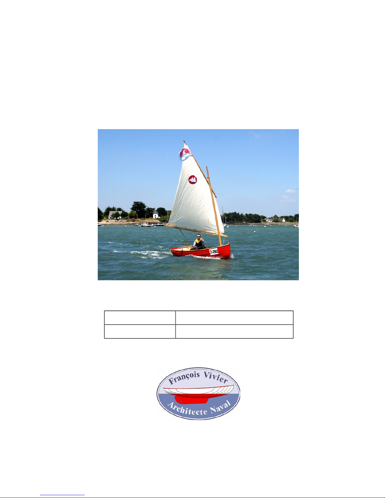
2.2. Boat presentation
Morbic 12 was designed to be:
✔ A dinghy, able to take 1 to 3 crew, with a performing balanced lug, as the International 12 feet which has
been an Olympic class.
✔ A "sail and oar" boat, able to sail anywhere. The moderate size makes Morbic 12 an ideal boat for fre -
quent single handling but she is able to take a crew of 3 and is fitted with 2 rowing thwarts.
✔ And also a simple motor boat, with its generous transom width. A cut-out in the transom allows to fit a
short-shaft outboard motor.
The small size of Morbic 12 allows such a multi-purpose use. Being light, she may be rowed easily, despite
her generous breadth giving stability for sail and motor. Morbic 12 is:
✔ A practical boat, the flat bottom making easy hauling on the strand,
✔ A modern design, with clinker plywood, for easy construction by a first time home builder,
✔ Simple with the pivoting and removable centreboard and minimal structure items,
✔ Safe with large side buoyancy tanks,
✔ Light and so effortless,
✔ 2 rig options : standing lug (picture) or sloop lug (with a jib).
✔ And all that keeping the lovely looking of a classic boat.
2.3. Motor version
There is also a purely motor version, without a centreboard and rudder and with a large locker forward. It is
built from a separate plan package.
2.4. Building time, tools
It is difficult to give an estimate of the time of construction, so much this one varies from one builder to an other, according to the experience possibly gained during former constructions. The tools you have at disposal
and you are able to master influence the working time. Some boats are true works of art, others are rather of
simple and rustic style.
The cutting up of timber takes also time which could be sub-contracted. Only basic portable tools are neces sary: drill, screw driver, jigsaw, electric plane (especially for mast and spars), without forgetting a good quantity of screw clamps.
The building time is about 200 hours, using precut timber. Construction time may be doubled for a first con struction project and if you want a high quality finish. These times are complete, including rig, fitting and paint ing. To build yourself such a boat supposes that you are looking mainly for the satisfaction of a beautiful work,
without being to much worried by time constraint.
This document is the property of François Vivier Architecte Naval. It shall not be copied, transmitted to any other person,
nor published as a whole or partly, without the written consent of the architect.
Page 4

March 2017 Building Morbic 12 Page 4/21
2.5. Compliance to regulations
WARNING
Morbic 12 is a boat that may capsize. Thus it is important:
to be equipped in order to withstand immersion into water,
to be prepared to right the boat,
to be always vigilant, to carry the sail appropriate for the wind and the sea state,
particularly if no external assistance is available.
Morbic 12 is designed in compliance with the requirements of the European Recreative Craft Directive
1994/25/CE amended 2003/44/CE.
It is designed to sail in the following categories:
✔ In category C, with a maximum of 2 persons on board (maximum loading 200 kg)
✔ In category D, with a maximum of 3 persons on board (maximum loading 250 kg)
The minimum crew is one person, as the boat may be right up by one person only in calm sea conditions. It is
recommended to be at least two on board when sailing in poor wind and sea conditions or away from any pos sible assistance.
The maximum power of the outboard motor is 3 kW.
The definition of these categories is pointed out below:
Category C (Inshore): designed for trips in coastal waters, large bays, estuaries, lakes and rivers where conditions up to, and including, wind force 6 and significant wave heights up to, and including, 2 m may be experienced.
Category D (Sheltered waters): designed for voyages in close coastal waters, small bays, lakes, rivers and
canals where conditions up to and including wind force 4 and maximum wave heights up to and including 0,3
m may be experienced.
NOTE: The significant wave height is the mean height of the highest one third of the waves, which approxim ately corresponds to the wave height estimated by an experienced observer. Some waves will be double this
height.
This document is the property of François Vivier Architecte Naval. It shall not be copied, transmitted to any other person,
nor published as a whole or partly, without the written consent of the architect.
Page 5

March 2017 Building Morbic 12 Page 5/21
3. Right of use and general information
3.1. Right of use
The purchase of plans gives the right to build one unit, by an amateur builder. They can be sold only by the
naval architect (François Vivier) or approved partners (see my web site).
Plan package, comprising the present manual and all the attached documents listed on page 2, is the prop erty of the architect. Except for the needs of construction and purchasing (sail plans, material lists...), the doc uments may not be reproduced, transmitted to a third party, nor published entirely or partly, without written au thorization from the architect.
3.2. Plan number
The plan number, registered on the front page of this manual, is specific to the purchaser and must be re called in any correspondence with the architect or Icarai (builder and kit seller).
Please inform the architect when the boat is first launched, and of change of address or ownership while
building.
3.3. Liability of the builder
Morbic 12 was designed with care and in full compliance with the European regulations. However, each boat
is built under the whole responsibility of its builder, and sails under the whole responsibility of its crew. Both
the architect and Icarai (boats from a kit) decline any liability in regard to people, legal entities, and property
resulting from construction and/or from use of a boat built from the plans.
3.4. Respect of the weights, scantlings, materials, and buoyancy
Amateur builders should be careful to note the necessity of respecting the plans and specifications, especially
scantlings and choice of materials, so that the boat does not become too heavy. Such extra weight would
make it less seaworthy, more difficult to launch and retrieve, and would involve a risk of overloading the road
trailer. Conversely, it is strongly dis-advised to reduce scantlings or to use materials of lower quality. Respect ing the specifications concerning volumes of buoyancy is an essential condition for compliance with EC regu lations.
3.5. E-mail assistance
If you encounter difficulties during construction, or if you have suggestions to make, please feel free to contact
the architect (preferably by e-mail or phone). Specify the number and the date of the plan (see front page).
We will answer your questions and, if necessary, update the plans to benefit other builders.
François Vivier Architecte Naval
7, avenue des Courtils – 44380 Pornichet - France
tél : 33 (0)6 74 54 18 60
e-mail : fr@vivierboats.com
www.vivierboats.com
Note: I am always happy to receive pictures and news about the boats I have drawn !
3.6. Supplies, kit
Materials and fittings needed for construction, in particular those specific to the boat, can be sourced from my
partners (see my web site): marine plywood (panels or NC cut parts), sawn timber, centreboard, fittings, sails,
outboard motor, trailer.
I have observed that to buy a kit allows the amateur builder to avoid bad surprises, un-compliant purchases,
high delivery costs and generally is a cheaper and easier way that to try to source all different materials and
equipments.
This document is the property of François Vivier Architecte Naval. It shall not be copied, transmitted to any other person,
nor published as a whole or partly, without the written consent of the architect.
Page 6
March 2017 Building Morbic 12 Page 6/21
4. Plywood Kit and full size patterns
New (April 2015): the Morbic 12 plan package comes now with dimensioned drawing. Therefore, kit or full size
patterns are optional.
4.1. NC cut plywood kit
The kit includes all the plywood parts necessary to the construction precut on numerically controlled machine.
The majority of parts are at final dimension or require only little fit. Refer to the appendix 2 which gives the
nesting plans of the parts in all panels. The planking strakes are assembled by “puzzle joint”, as shown on the
following sketch. You have to glue them together and get a plank ready to be placed on board with only ends
adjustments:
Puzzle joints require to be glass-epoxy sheathed inside, at least in areas which may be in contact with trailer
rollers or supports during launching and recovering.
The kit offers up the following advantages:
✔ Reduction of the construction time: you will save the time of marking and cutting many parts within many
plywood panels.
✔ Reduction of the need for space to scarf and cut out the panels.
✔ Reduction of the risk of construction error and improvement of the assembly accuracy.
Kit is to be ordered to boat-builder Icarai (see page 5) in France of other representatives abroad. If you buy
the kit, you do not have to order the polyester patterns.
The construction described in the following pages is based on the assumption you are working from
full size patterns. If you have the plywood kit, some task are deleted.
4.2. Full size patterns on polyester film
These patterns give the marking of moulds, bulkheads, centreboard case, transoms, planking, rudder...
Bevels are drawn. Position of battens and various pieces to be fixed on the bulkhead faces are also marked.
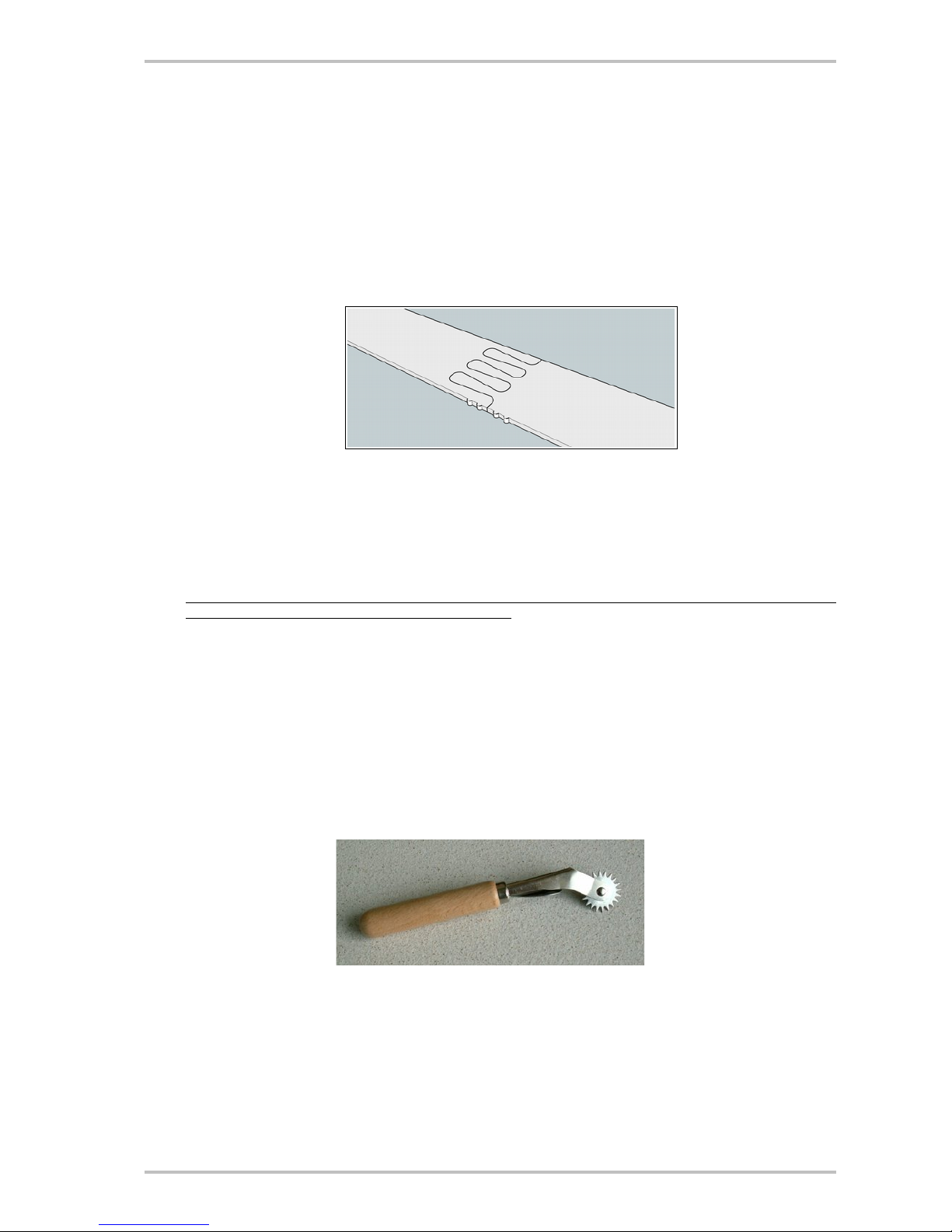
The support is a polyester film (also said mylar), very resistant to tearing and not subject to humidity variations. Marking are to be transferred to the plywood sheets.
For that purpose, you may use a screwdriver grinded to form a spike. With a hammer, the wood is marked
through the film. You may also use carbon paper spread between film and plywood. An other very efficient
method is to use a tracing wheel as used by dressmakers :
Polyester patterns are delivered in a resistant tube and are to be ordered from François Vivier Architecte
Naval SARL according to current price list.
This document is the property of François Vivier Architecte Naval. It shall not be copied, transmitted to any other person,
nor published as a whole or partly, without the written consent of the architect.
Page 7

March 2017 Building Morbic 12 Page 7/21
5. Summary of the construction process
Before starting the construction, the general process of which is presented in the following pages, it is import ant to read the whole manual and plans for a good overall comprehension. That remains true at all stages. A
good preparation will avoid errors, sometimes not easily retrievable, and will save time.
The general process is as follows:
✔ Cut-out of the moulds and main girder from chipboard or MDF panels,
✔ Assemble the transom, the stem, the false stem, all made of several layers,
✔ Set up all elements on the building frame,
✔ Lay down clinker planking,
✔ Fit the false stem, make epoxy fillets on the outside hull,
✔ Turn over,
✔ Fit the gunwales, rub-rails, seat risers, buoyancy tanks,
✔ Sheath the sole and garboards,
✔ Fit the centreboard case, mast step and mast partner, foot rests,
✔ Turn over for outside hull finishing works,
✔ Sheath the sole and garboards,
✔ Fit the skeg
✔ Paint the hull
✔ Turn over again for inside finishing works,
✔ Painting and varnishing
✔ Fittings
The following tasks may be done at any moment and scheduled according to your own space and weather
constraints:
✔ Centreboard,
✔ Rudder,
✔ Mast and spars,
✔ Oars...
This document is the property of François Vivier Architecte Naval. It shall not be copied, transmitted to any other person,
nor published as a whole or partly, without the written consent of the architect.
Page 8

March 2017 Building Morbic 12 Page 8/21
6. Chronological description of construction
6.1. Building frame
Patterns
Appendix 2
Plan 12
Sheet 22
The building frame is based on a stiff main girder (250 X 350 mm), made of chipboard or MDF
panels. MDF is easier to work out and is chosen for NC cutting.
The fore face of the main girder will be used as support for the fore bulkhead of the boat. There fore, it has to be perfectly perpendicular to the other faces of the girder.
Doublers are screwed into the girder sides in order to make slots for the proper positioning of
girder supports and station moulds (see plan 12).
The main girder is supported by chipboard/MDF transverse parts. If preferred to ease work, the
main girder may be raised using saw horses or any other available means.
Then set down all six station moulds and check they are perfectly aligned and spaced. 3 of these
moulds are in fact bulkhead supports. Only bulkheads are part of the finished boat. Holes (6 mm
diameter) are drawn on the patterns (and already cut-out in the kit) to allow quick and good positioning of these bulkheads.
Look carefully at plan 12 to place properly the bulkheads (for or aft of station moulds).
Before bolting the bulkheads, protect the station moulds with plastic film to avoid gluing the hull
planks on these moulds. Notice that moulds are voluntarily recessed from the bulkhead outline in
the overlapping area.
6.2. Cut-out and assembly of structural parts
Patterns
Appendix 2
Appendix 1
Plan 12
Sheet 22
All parts are cut-out using the patterns. Several parts need to be pre-assembled:
✔ The transom is made of 2 layers. The inner layer is cut-out with 2 mortices in order to fit into
ends of side seats longitudinal bulkheads. Glue both layer using bolts into the alignment holes
to avoid slipping of parts when glue is curing. Afterwards, remove bolts and fill in the holes
with epoxy putty. Bolts may also be replaced by screws which may be kept in place. Upper
edges of both layers of transom are aligned. Other edges are slightly shifted. This allows to
get the proper bevel as follows:
Gluing of transom and centreboard (background)
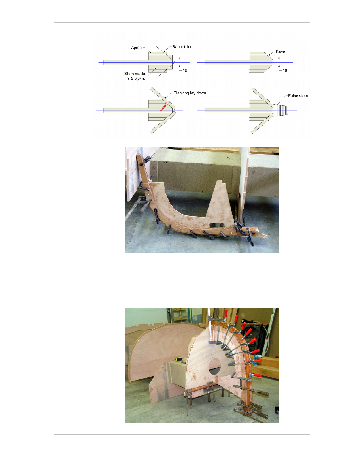
✔ The stem is made of 3 layers of 10 mm plywood. The centreline layer ensure a link with bulk -
head 5. An additional layer of 6 mm ply is glued over both sides to make an apron, increasing
the gluing area of the hull planking over stem bevels. As for the transom, use bolts to keep the
alignment of parts when glue is curing. The following sketch show how to get the stem bevel:
This document is the property of François Vivier Architecte Naval. It shall not be copied, transmitted to any other person,
nor published as a whole or partly, without the written consent of the architect.
Page 9
March 2017 Building Morbic 12 Page 9/21
Stem gluing
✔ Mark the clinker lines on the aprons to ease plank lay down. If you have the kit, small notches
give the position of clinker lines. The marked line is the edge of the « inside » plank, which is
laid down first.
✔ The false stem is laminated at this stage, using the stem as a mould. Note that cut-out have
been made in the centreline layer to allow clamping.
This document is the property of François Vivier Architecte Naval. It shall not be copied, transmitted to any other person,
nor published as a whole or partly, without the written consent of the architect.
Page 10
March 2017 Building Morbic 12 Page 10/21
✔ The fore bulkhead (# 5) is made of 2 layers of 6 mm plywood. The bevel is obtained in the
same way than for the transom. Add a batten on top (fore side) which will be used to lay down
the deck. Shift this batten upward (3 mm about) to allow bevelling according to sheer.
✔ The fore bulkhead and stem are assembled, taking care of orthogonality.
Then all parts are laid down on the main girder:
✔ Bolt bulkheads and stem to supporting station moulds:
Note that the mould is recessed from the bulkhead to avoid undue gluing during the planking process
✔ Set down the longitudinal bulkheads which must be glued to bulkhead 3. Add an epoxy fillet or
a batten inside the buoyancy tank.
✔ Lay down the transom which is glued to the ends of the longitudinal bulkheads. Glue inside
the transom the beam (35 X 25) which will receive the aft deck. It is better to bevel this beam
before gluing (take off the angle on plan 21).
See the epoxy fillet between transversal and longitudinal bulkheads
Transverse bulkheads have to be bevelled to receive the hull planking. Use a long batten to estim ate the quantity of wood to be planed off.
The mid-bulkhead (# 3 under main thwart) will be cut out at centreline at a letter stage, just before
setting down the centreboard case.
Longitudinal bulkheads do not require bevelling. Just do it if necessary when laying down the hull
planking.
This document is the property of François Vivier Architecte Naval. It shall not be copied, transmitted to any other person,
nor published as a whole or partly, without the written consent of the architect.
Page 11

March 2017 Building Morbic 12 Page 11/21
6.3. Strakes preparation
Appendix 2 The patterns give the final shape of strakes (hull planks). They may be cut without any margin, ex-
cept at ends. The average overlap between strakes is 20 mm. However, the actual overlap may
vary between 10 to 25 mm to take in account possible inaccuracies of the design and building pro cess.
The sole (bottom planking) is made of 2 scarfed planks. Cut-out first both parts, then assemble by
scarf taking care of a perfect alignment. For that purpose, draw the centreline on each plank.
When gluing, check alignment and hold in place with a few screws of nails in order to avoid any
slippage.
For other strakes, scarf firstly the full plywood panels, then mark from the patterns and cut-out.
Attention: this require space. If you build in a small room, it is better to scarf panels and cut-out
strakes before setting up the building frame.
Then sheath the inside face of sole, as it is easier to do it now that into the boat at a later stage.
For the same reason, you may also glue and screw from outside the foot rests on this sole.
6.4. Lay down of the sole and first strake (garboard)
Plan 12
Plan 21
Plan 22
Sheet 51
The sole, when glued to the structure, will make the boat definitely stiffer. Bulkheads are to be per fectly aligned before gluing. For that purpose, draw the centreline on the inner face of sole and on
each bulkheads. Check also the spacing of bulkheads (see plan 12). This plan gives also the posi tion of the fore end of the centreboard slot, in order to get the good longitudinal position of the
sole.
The fore end of the sole, or rectangular shape, will be plane away when fitting the false stem. In final, only a small amount of wood will be kept.
The liaison between the sole and the garboard is done on the stitch and tape principle. As the sole
is thicker than the garboard, it has to be planed out all around, on the outer side, to get an edge
thickness of 6 mm about. See plan 22.
In practice, only a few number of wires is required, in addition to some temporary screws into bulk heads. Then the joint is filled-up with epoxy putty. When cured, remove the wires and fill the re maining open joints. Fair and sheath with a glass tape.
The following tasks are made at later stages:
✔ Sheath all the sole and garboard area, to get a tough skin, wearing resistant.
✔ After turning over, apply epoxy fillet and glass tape on the sole/garboard joint and sheath the
sole and garboard area. There is often sand in the boat and a tough surface is also much better. Aft, sheath also the lower part of the longitudinal bulkhead (2 or 3 cm).
6.5. Lapstrakes lay down
Sheet 43
Sheet 44
Sheet 12
The recommended technique is to glue the strakes using temporary screw (sheet 44). They are
also glued to stem and transom. Strakes are normally laid down without adjustment. As already
written, the overlap may vary around the average 20 mm value.
The small thickness of strakes makes necessary in some area to fill-in a V joint with an
epoxy fillet (see sketch).
The general process is as follows:
✔ Mark and plane out the bevel on the previous strake.
✔ Lean the strake being fitted against the building frame, well positioned according to notches in
bulkheads/station moulds and according to marks on the stem. As said, the average overlap is
20 mm.
✔ Shape the ends of strakes as explained in sheet 44.
✔ Then glue the strake hold in place with some screws into stem, transom and bulkheads. Tem-
porary screws may be used into station moulds.
✔ Lay down alternately strakes on port and starboard sides.
This document is the property of François Vivier Architecte Naval. It shall not be copied, transmitted to any other person,
nor published as a whole or partly, without the written consent of the architect.
Page 12

March 2017 Building Morbic 12 Page 12/21
Strakes lay down
6.6. External completions of the hull
Plan 21 Before hull turning over:
✔ Fit the false stem. Shape this false-stem in order to get a flat surface on the fore end (14 to 16
mm wide) allowing to screw down a brass keel band.
✔ Apply epoxy resin on all plywood edges and add epoxy fillet into joints when required.
6.7. After turn-over
Plans 21 & 22
Lay down 2 transverse temporary battens over the hull, one at station 1 and the other at station
4.2, to check the hull is not twisted.
Lay down the fore deck and the aft decks/seats to check the curvature of the hull planking. If ne cessary, the hull may be squeezed with a rope or spread with temporary beams.
Check that the hull is well shaped. If necessary, it is possible to adjust the sheer line with a plane.
At this stage, the hull is still flexible. It will become stiff after adding other inside structure elements.
Then saturate all plywood strakes edges with epoxy resin, as already done outside. Sheath the
sole-garboard joint with a tape and sheath the full sole and garboards with cloth and epoxy as
shown on transverse structure plan.
6.8. Rub-rail, gunwale, quarter knee
Plans 21 & 22
Appendix 1
Lay down the gunwale (inside planking). Be careful as the glued parts are very slippery. In addition
to clamps, place some screws.
In order to ease gunwale adjustment at ends, it is made of two parts. The joint is just under the
thole board, so hidden when the boat is finished.
In the thole pins area, the gunwale is doubled with a second layer. Take care not to chamfer the
first layer in the doubled area, as well as in the quarter knees areas.
As we have not made any rabbet to cover the hull plywood edge, gunwale and rub-rail will be
placed about 2 mm above plywood edge as shown on the sketch. The slot will be filled up with
epoxy putty. If the gunwale is to be varnished, use wood powder to thicken epoxy in order to get
an appropriate colour. Then the full assembly may be planed out:
Cut out, adjust and fit (glue and screw) the quarter knees. Screw are preferably set from outside
planking. The quarter knees shape is given on the full size patterns.
A lower rub-rail may be added at the low edge of sheer-strake. It gives extra protection and a more
traditional look.
If the gunwale is varnished, it is preferable to cover screws with wooden bungs, or at least with
epoxy putty made with wood powder.
This document is the property of François Vivier Architecte Naval. It shall not be copied, transmitted to any other person,
nor published as a whole or partly, without the written consent of the architect.
Page 13

March 2017 Building Morbic 12 Page 13/21
Rub-rails and stem cleat on a Morbic 10
6.9. Seat riser
Plans 21 & 22
Appendix 1
A seat riser is placed at 170 mm under sheer line (see longitudinal structure plan) in the thwart(s)
area. At the after end, the seat riser is kept just over the sheer-strake edge (inside) and then is
closer to sheer line. In the side seat area, use a transverse batten laid over the longitudinal bulkheads to mark the position of seat riser on the hull planking. In the fore section, mark at 170 mm
under sheer line.
Glue the seat riser with small screws (temporary or not) from outside. It is preferable to bevel the
upper face before gluing:
In order to support the fore thwart (balanced lug only), the seat riser is doubled. This second layer
is glued and screwed from inside.
6.10. Buoyancy compartments
Patterns
Plans 21 & 22
Sheet 71
As shown on plans, there is 3 buoyancy compartments, one fore and one aft on each side. To
save weight and allow to stow some belongings in a dry space, they are not filled up with foam.
Therefore it is very important to have them perfectly watertight. In case of doubt, is is always possible to fill them with expanded polystyrene.
Compartments are closed with the fore deck and the side seats. Cut-out apertures at hatches diameter. Make epoxy fillets on all joints inside and apply paint before closing. Paint also the inside
face of deck and side seats, except in gluing areas.
At this stage, fit the upper frame at station 3, so it could be screwed through the bulkhead. It is cut
out around the seat riser. Insert a vertical long screw through the gunwale into the frame head. For
that purpose, drill a wide hole (4 mm for a 5 mm screw) and fill up with epoxy putty before screw ing. This prevents splitting wood and gives a good link.
Before closing the compartments, take care to have a continuous batten all around to ensure wa tertighness. In the fore compartment, glue a plywood batten under the gunwale. Leave a 10 mm
gap between gunwale and batten, corresponding the the deck thickness. Under the side seats,
glue the doublers 20 mm thick which allow to screw down the main thwart. Mark the position of the
srews on the upper side.
Aft, glue the curved beam made of 2 layers of 10 mm plywood.
Lay down the covers to check that all is well adjusted.
If you have chosen the sloop rig, the fore deck is lengthened afterwards with two layers of 6 mm
plywood. Make a partial scarf to make the joint with the fore part of deck (see detail on plan 21S).
Prepare the samson post which is screwed through the bulkhead 5. Carve a mortice in the fore
This document is the property of François Vivier Architecte Naval. It shall not be copied, transmitted to any other person,
nor published as a whole or partly, without the written consent of the architect.
Page 14

March 2017 Building Morbic 12 Page 14/21
side of post to receive the bowsprit tenon. The mortice is positioned in order that the bowsprit rake
is about 2° above horizontal. The fore deck is cut-out at samson post position.
Then, you are ready to glue the fore deck and the side seats. Apply a thick epoxy joint all around in
order to avoid any leak. After gluing, add epoxy fillets between deck and gunwale (fore) and
between side seats and hull planking (aft). Use masking tape to avoid epoxy overflow and get a
neat joint, in particular if you intend to varnish.
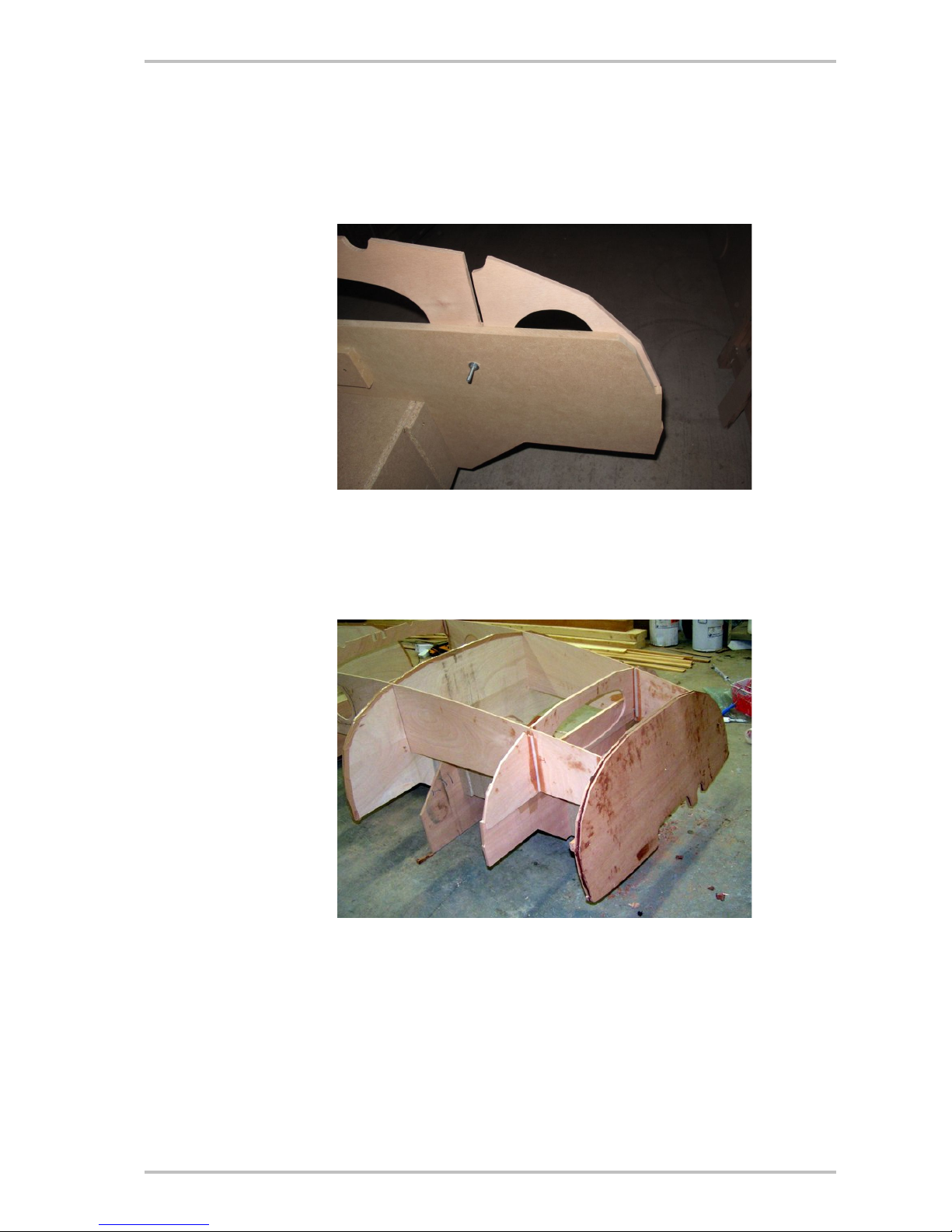
Aft compartment ready to be closed
Note also that bulkhead 3 has been cut out to receive the centreboard case
(attention : this is the first boat and the shape of this bulkhead is now modified)
If the compartments are not filled up with foam, the EU regulation (ISO standards) require a water tightness test. The small size of Morbic 12 allows to do that without special equipment as you may
turn the hull in various positions. Fill up each compartment with water and close the hatch covers.
Move to boat is every position to check there is no leak. Be careful as the boat is heavy. You need
several people to help and old mattresses or any other means to avoid damage to the hull. It is
preferable to test each compartment separately to avoid too much weight. Take pictures to be able
to give assurance that the test has been done.
6.11. Centreboard and centreboard case
Patterns
Plans 21 & 22
Appendix 1
Appendix 2
The centreboard is pivoting but may be easily taken out (boat in water) to reduce weight if the boat
is to be carried over a car top. It is streamlined is the same way than the rudder (see plan 25).
Posts and spacers, 25 mm wide, are adjusted at both ends and aft edges. Logs are to be cut-out
according to sole curvature (there is a pattern in the kit). Upper carlins are extended afterwards is
order to be used as supports for the main thwart.
The case sides are doubled outside in way of the pivot slide. The centreboard is made of two
10 mm plywood layers. Drill a hole for the pivot without any margin in order than the pivot is forced
into the hole. Add epoxy to ensure that the pivot may not be lost.
If the centreboard is made of okume plywood, it is preferable to epoxy sheath in order to give a
better resistance. Add some extra cloth of the fore and low edges before the general sheathing.
Centreboard case pre-fabrication
A notch is cut out in the centreboard handle. This allows to insert a shock-cord (8 mm diameter)
lashed between two eye clips screwed to logs. These eye clips are positioned just under the pivot
This document is the property of François Vivier Architecte Naval. It shall not be copied, transmitted to any other person,
nor published as a whole or partly, without the written consent of the architect.
Page 15

March 2017 Building Morbic 12 Page 15/21
position. This shock-cord maintains the centreboard either in raised or low position. In addition, it
prevent the centreboard to be lost in case of capsize.
Centreboard handle with the shock-cord laid into the notch
We have now added a second carlin (cleat on plans) allowing to jam
the shock-cord for a better hold of the centreboard in both position.
The case is fully pre-assembled before lay down on board. Cut-out the centreline part of the bulk head 3 and insert the case. Apply a thick coat of epoxy between logs and sole and screw through
the sole to ensure watertightness. Glue the posts 20 X 25 between case and bulkhead 3.
Remove excess epoxy before curing. When epoxy is cured, adjust the sole slot which was made
voluntarily shorter and narrower.
Attention : foot rests are to be fitted after the centreboard case.
6.12. Foot rests
Plans 21 & 22
Appendix 1
Foot rests are simple transverse battens epoxy glued to the sole. They are also screwed from out side. Therefore, they have to be fitted before hull epoxy sheathing. The plan shows standard posi tions which may be tuned to your own size.
Note that bulkhead 3 act as a foot rest for the fore thwart (balanced lug version). In order to give
extra strength and avoid damaging the plywood, a batten is fitted on the fore face of this bulkhead.
6.13. Mast partner and mast step (balanced lug version)
Patterns
Plans 21T &
22T
Appendix 1
Appendix 2
The mast partner (hole into the fore deck) is cut-out at the dimensioned position. A plywood dou bler is glued underneath to reinforce the deck. Drill a hole on port side of mast to give way to the
sail tack line (close to the mast ; position is dimensioned on plan 21T).
The mast step is made of two layers of 10 mm plywood, laid over the stem extension. Glue and
screw, on both sides of stem, wooden blocks allowing to screw down the mast step. Make a drain
to avoid any water retention into the mast step mortice. The mast step is extended on port side in
order to fasten an eye-bolt for the tack line purchase.
Note that if you are not satisfied with the boat balance under sail, it is easy to replace the mast
step with the mortice shifted forward or afterwards.
6.14. Mast partner and mast step (lug sloop version)
Patterns
Plans 21S &
22S
Appendix 1
Appendix 2
The mast partner is an open one (half circle). The mast is fasten to the partner by mean of a lash ing between two eye-bolts.
Drill a hole on port side of mast to give way to the sail tack line (close to the mast ; position is di mensioned on plan 21S).
The mast step is made of three layers of 10 mm plywood. An eye-plate is screwed down for the
tack line purchase .
This document is the property of François Vivier Architecte Naval. It shall not be copied, transmitted to any other person,
nor published as a whole or partly, without the written consent of the architect.
Page 16

March 2017 Building Morbic 12 Page 16/21
6.15. Skeg and external completion of the hull
Patterns
Plans 21 & 22
Appendix 1
To improve the link between hull and skeg, a 100 mm wide plywood doubler is glued on the sole at
centreline, between transom and bulkhead 1.
Then to boat is turned over again, upside down.
Sheath the sole and both garboards:
Fit the skeg which is screwed from inside with long screws. Epoxy fillets are made between skeg
and sole to improve the link. The profile of the skeg is given on the full size patterns. Otherwise,
you may draw this shape from the dimensions given on plan 21. Make a pattern with thin plywood
according to sole curvature and use the pattern to cut the skeg into the 26 mm thick timber. The
skeg is streamlined, reducing the thickness to 20 mm about (just a little more than the keel band)
at the lower and aft edges.
Paint the hull. Then it will not be necessary to turn over again.
Screw down the keel bands (brass half rod or bar, 12 mm wide). There is one keel band fore, from
stem head to stem aft end, and one aft on the skeg, extended to the lower rudder pintle.
This document is the property of François Vivier Architecte Naval. It shall not be copied, transmitted to any other person,
nor published as a whole or partly, without the written consent of the architect.
Page 17

March 2017 Building Morbic 12 Page 17/21
6.16. Inside arrangement
Patterns
Plans 21 & 22
Sheet 71
Appendix 1
Turn over again, boat upright.
Resume after deck and side seats installation and fit the trim (8 X 26) protecting the plywood
edges.
Temporary spans may be used to glue the side seats trims, not using screws.
Adjust the thwarts. The fore thwart (balanced lug rig only) is screwed down into the seat risers.
The main thwart is screwed from underneath through the 20 X 20 battens of the buoyancy com partments. If necessary, the thwart may also be screwed into the seat risers, through the seats
covers. In addition, two small “stop pieces” under the thwart on both sides of centreboard case ensure a better transversal attachment of the case.
On this beautiful Morbic 12, built in UK by boat-builder Adrian Donovan,
you can see the new arrangement he suggested to stow the oars.
6.17. Drain plug
Appendix 3 Fit a drain plug to empty the boat when on trailer. On this small boat, the drain plug may be loc-
ated at bottom of transom as shown on plan 22. The plug itself is inserted from outside. Limber
holes are made into bulkhead 1 to ensure proper water flow.
6.18. Thole pins and oars
Plans 21 & 22
Plan 41
Appendix 3
Sheet 81
Sheet 82
Rowing oars are lightly designed to allow rather long distance, even in open sea. There is no need
to control blade angle and the pivot point cannot move.
Bulls are fitted with 2 holes. The inner hole is the usual one. The outer one gives more pulling force
on the blades and is useful in bad wind or sea conditions.
Keep on board a paraffin fragment and rub the thole pin with it. It is an excellent lubricant, which
avoids any chafing noise and does not stain cloths or sail.
These rowing oars are not designed for sculling. If you need it for a short ride in harbour, do not
This document is the property of François Vivier Architecte Naval. It shall not be copied, transmitted to any other person,
nor published as a whole or partly, without the written consent of the architect.
Page 18

March 2017 Building Morbic 12 Page 18/21
force. If you intend to scull frequently, it is better to make a dedicated oar, in ash or Douglas fir,
2.7 m long.
Oars are simply stowed on the sole.
Each thole board is made of hardwood and screwed into gunwale. The upper face is transversely
well rounded to avoid damaging oars when rowing. In the longitudinal way, it has to be planed horizontal in order to keep oar blades vertical.
Both thole board and gunwale are drilled to receive the thole pin (14 mm brass rod). Do not drill
too wide, as the thole pin will move too much when the wood is dry, even if it is not possible to put
away the pin when the wood is wet. The pin top is to be well rounded to avoid hurting crew. A small
eye strap under gunwale allows to use a safety line in order not to lose the pin.
Thole pins are to be vertical in the longitudinal plan. This prevents the oars to go out from the pin
when rowing. Pins have to be inclined outwards in the transverse plan, corresponding to the average angle or oars (horizontal or in water).
It is also possible to use classic oars with bronze rowlocks (also said oarlocks or crutches). In that
case, a small safety line or chain is necessary to avoid loosing rowlocks in case of capsize.
6.19. Rudder
Plan 25
Appendix 3
Sheet 72
The rudder is made with a pivoting blade according to plan and sheet 72. There is one lifting line.
Make 2 knots for lower and tilted position. It is advisable to attach the end of the line to the hull, in
order to avoid any loss of rudder. If the rudder blade is made of okume plywood, sheathing is
preferable as for centreboard.
6.20. Rig (balanced lug version)
Plans 21T &
22T
Plans 31 or 33
Plan 35
Appendix 3
Sheets 81 & 82
This rig is ideal for single-handling or if you want to use oars with two rowers.
You have the choice between a vertical cut sail, more traditional, or a cross cut sail with battens,
more efficient.
Refer to plans and sheets. The tack line is rigged as shown on last page of sheet 82. It is driven
through deck, close to mast and come to a block at mast step. A purchase is rigged on side of
centreboard case, allowing direct tuning by the helmsman. The lug sail needs frequent tuning of
the tack purchase, according to wind force and point of sail. This purchase is an improvement not
shown on pictures.
This document is the property of François Vivier Architecte Naval. It shall not be copied, transmitted to any other person,
nor published as a whole or partly, without the written consent of the architect.
Page 19

March 2017 Building Morbic 12 Page 19/21
When you use the oars, the mast is lowered and stowed, step forward, under the fore thwart but
above the main thwart. The sail, rolled over the yard, is simply resting on thwarts, under fore deck.
Note: the sail plan show a vertical cut sail. It is also possible to have the same sail cross cut but
without batten. Many sail-makers are more comfortable with this method, resulting in a better
shape and performance.
It is also possible to add on boom a half jaw, as described in the next paragraph (sloop version). It
prevents the boom to shift forward, which happens when the tack is not properly tightened.
6.21. Rig (lug sloop version)
Plans 21S &
22S
Plans 32 & 36
Appendix 3
Sheets 81 & 82
Refer to plans and sheets. Refer to plans and sheets. The tack line is rigged as shown on last
page of sheet 82. It is driven through deck, close to mast and come to a block at mast step. A purchase is rigged on side of centreboard case, allowing direct tuning by the helmsman. The lug sail
needs frequent tuning of the tack purchase, according to wind force and point of sail. This pur chase is an improvement not shown on pictures.
The mainsail halyard is belayed on a cleat, screwed to mast under mast partner. This cleat allows
to belay halyards when the boat is unmasted.
The jib is tacked on bowsprit end. The jib tack line comes through a block and is led to a belaying
pin on the mast partner. A bobstay with a small purchase pull down the bowsprit against the stem
head. The purchase line is belayed on a cleat screwed on a bowsprit side. This purchase must be
well tighten. The jib halyard is led to the other belaying pin.
Jib sheets come to a cleat screwed on the aft edge of main thwart :
See mainsail and jib sheets arrangement
When you use the oars, the mast is lowered and stowed, step forward, above the main thwart. The
sail, rolled over the yard, is simply resting on thwarts, under fore deck.
It is possible to fit (glued with generous epoxy fillets) a half jaw on boom side as shown on the fol lowing sketch:
This prevent the boom to shift forward and hamper the jib and jib sheets. This half jaw is made of
plywood (3 lyers 6 mm). Glue a protective leather inside to protect the mast from chafing. Keep
enough play between jaw and mast to avoid jamming. With this half-jaw, the down-haul is attached
on the boom through the hole in the jaw. Therefore, the hole in the mast thwart has to be shifted
backward accordingly.
The half-jaw has to be located to get a 200 mm distance between the mast axis and the boom fore
This document is the property of François Vivier Architecte Naval. It shall not be copied, transmitted to any other person,
nor published as a whole or partly, without the written consent of the architect.
Page 20

March 2017 Building Morbic 12 Page 20/21
end.
Note: the sail plan show a vertical cut sail. It is also possible to have the same sail cross cut but
without batten. Many sailmakers are more comfortable with this method, resulting in a better
shape and performance. It is also possible to use the battened sail of plan 33.
6.22. Painting
Fiche 91 The sheer-strake may be painted with a different colour. Prefer a light colour for the hull, which en -
hance the clinker lines. A satin finish gives a more traditional appearance.
The inside may be varnished. However it is preferable to use a matt paint for the sole and gar boards, easier to maintain than varnish. You may also use a non skid paint for sole and garboards.
7. Equipments
7.1. Trailer
Morbic 12 may be carried over a car top. Check that the weight of the boat is in conformity with the
requirements of the car and the supporting bars.
A combination trailer, including a launching trolley with low pressure tyres which can be rolled on
sand beaches, is a good choice if the boat is currently launched from a beach.
Simple road trailer, without launching trolley, for ramp launching
7.2. Motor
Morbic 12 transom is designed to receive a short shaft outboard motor of 4 hp. In practice, a small
tender motor (2 to 3 hp) is fully adequate.
8. Under sail
Morbic 12 is a small boat, so sensitive to load under sail. Be careful to keep a convenient trim. The
crew must not be grouped aft nor too much forward.
When single-handed, the helmsman has to be seated close to the main thwart. In that case, the
use of a tiller extension is recommended.
This document is the property of François Vivier Architecte Naval. It shall not be copied, transmitted to any other person,
nor published as a whole or partly, without the written consent of the architect.
Page 21

March 2017 Building Morbic 12 Page 21/21
8.1. Capsize test
It is recommended to make a capsize and recovery test to check that you are able to do it in ad verse conditions and to detect any problem:
This document is the property of François Vivier Architecte Naval. It shall not be copied, transmitted to any other person,
nor published as a whole or partly, without the written consent of the architect.
Page 22

Morbic 12 – appendix 1 rev 8
Timber list
Items Version Wood
code
Quan-
tity
Thick.mmWidthmmLengthmmComments
Laminated false stem All A 10 3 30 1 100
Trim on stem head All A 1 10 32 120
Skeg All A or C 2 26 160 1 100
Aft gunwale All A 2 16 26 1 300
Fore gunwale All A 2 16 26 2 700
Rub-rail All A 2 16 26 4 000
Gunwale (layer 2) Balanced A 2 16 26 1 600
Gunwale (layer 2) Sloop A 2 16 26 900
Batten under side seats All A 2 20 20 1 750
Miscellaneous battens All A 1 20 20 4 000 Total length
Trim side seats All A 2 8 26 1 400
Trim aft deck All A 1 8 26 700
Trim mast partner All A 1 10 32 1 200
Doubler mast partner Sloop A 1 18 70 1 200
Seat riser All A 2 12 30 3 500
Seat riser (layer 2) Balanced A 2 12 30 500
Centreboard case logs All A 2 25 40 1 200
Centreboard case posts All A 1 25 30 1 000 Total length for 4 parts
Centreboard case spacer All A 1 20 25 450
Post between case and bulkhead 3 All A 2 20 25 350
Trim and cap centreboard case All A 1 10 38 700 Total length for 2 parts
Upper carlin centreboard case All A 2 16 26 800
Cleat to maintain the centreboard chockcord All A 2 16 26 500
Foot rest glued on bulkhead 3 Balanced A 2 16 26 250
Stem cheeks under mast step Balanced A 2 25 40 200
Beam between transom and aft deck All A 1 25 35 1 150
Tiller All A 2 21 70 1 200
Quarter knees, upper frames All A 1 20 150 900 Or equivalent area (figure 1)
Doublers to screw down the main thwart Sloop A 1 20 50 450
Page 23

October 2013 Morbic 12 Appendix 1 rev 8 - Page 2/2
Samson post Sloop A 1 56 56 600
Aft foot rests All A/C 3 30 30 400 Avoid oak, which does not glue properly
Fore foot rests Balanced A/C 4 30 30 200 Avoid oak, which does not glue properly
Fore thwart Balanced E 1 22 200 1 300
Aft or main thwart All E 1 22 220 1 500
Fore thole boards All C 2 30 45 250
Aft or main thole boards All C 2 35 45 250
Oars bulls (for 2 oars) All C 2 22 35 300 2 pairs for the balanced lug rigs
Oars wearing planks (for 2 oars) All C 2 10 50 400 2 pairs for the balanced lug rigs
Mast Balanced F 1 76 76 4 350
Mast Sloop F 1 76 76 4 400
Yard All F 1 50 50 3 100
Boom All F 1 50 50 3 100
Bowsprit Sloop F 1 50 56 1 200
Oars, loom (for 2 oars) All G 2 34 50 2 800 2 pairs for the balanced lug rigs
Oars, blades (for 2 oars) All G 4 34 40 1 100 2 pairs for the balanced lug rigs
Note : Given length takes into account end margins; given thickness and widths are dimension of final (planed) dimensions.
Figure 1, timber parts 20 mm thick:
Wood Code Main use Recommended species
A Glued main structure parts : stem, laminated
frames, gunwale…
Sipo, Sapele, Mahogany, Douglas fir
C Wearing parts Oak, Acacia, Iroko
E Thwarts Red pine, Douglas fir, Mahogany, Western red
cedar (the last one soft but light).
F Masts and spars Northern pine, Spruce, Douglas fir
G Oars Northern pine, Spruce
(Douglas fir or ash for a scull)
François Vivier Architecte Naval
2 October 2013
Page 24

Morbic 12– Appendix 2 - rev 10
Plywood list
Type Format Thickness Quantity Use
Marine all okume/gaboon 2 440 X 1 220 9 to10 mm - 7 layers 1 Centreboard, rudder, transom
Marine all okume/gaboon 2 440 X 1 220 9 to10 mm - 7 layers 1 Bulkheads, sole
Marine all okume/gaboon 2 440 X 1 220 6 mm – 5 layers 2 Side seats....
Marine all okume/gaboon 2 440 X 1 220 6 mm – 5 layers 4 Planking
Chipboard or MDF 2 440 X 1 220 15 mm 2 Moulds
Chipboard or MDF 3 100 X 1 530 15 mm 1 Main building frame support
The first panel (centreboard, rudder...) may be replaced by a harder wood: sapele, mahogany, makore, sipo, meranti, moabi (this last one very strong but
heavier). It is also possible to use such species for all panels but the boat weight will be increased by 15% about.
If you want to varnish the boat, sapele or mahogany plywood will give a better aspect. If available, you may also use plywood with sapele or mahogany faces
and okume inside layers.
For planking, joints are of the “puzzle” type. It is required to sheath locally the joints on the inner side.
The following pages give the nesting diagrams of the plywood panels with identification of each part.
The same NC cutting applies for both version, sloop or standing lug (misainier). Some parts are used for one version only.
If you are using full size patterns or dimensioned drawings, see nesting plan of strakes is last page of appendix.
François Vivier
Architecte naval
18 April 2015
Page 25

78
Ø76
Trou d'étambrai misainier
Mast hole standing lug
Trou pour bitte sloup
Samson post sloop
132
Morbic 12 - Contreplaqué marine okoumé (ou sapelli, moabi) 10 mm - 2 440 X 1 220 Panneau 1/2
Morbic 12 - Okume (or mahogany) marine plywood 10 mm - 2 440 X 1 220
Panel 1/2
Doublante ponté arrière
Aft deck doubler
Tableau pli extérieur
Transom, outside layer
Tableau pli intérieur
Transom, inside layer
Dérive
Centreboard
Dérive
Centreboard
Trou d'alignement 6 mm
Alignment hole 6 mm
Safran
Rudder blade
Safran
Rudder blade
Ame gouvernail
Rudder core
Ponté avant
Fore deck
Support ponté avant
Fore deck support
Doublante ponté arrière
Aft deck doubler
Etrier gouvernail
Rudder head
Etrier gouvernail
Rudder head
Axe gouvernail
Rudder pivot
Morbic 12 - Echelle 1/10
Page 26

Morbic 12 - Contreplaqué marine okoumé 10 mm - 2 440 X 1 220 Panneau 2/2
Panel 2/2
Morbic 12 - Okume / Gaboon marine plywood 10 mm - 2 440 X 1 220
Scarf 70 mm
Doublante pour aileron
Doubler for skeg
Cloison 1
Bulkhead 1
Joues gouvernail
Rudder cheeks
Pli axial étrave
Stem core layer
Etrave
Stem
Cloison 3
Bulkhead 3
Sole (arrière)
Sole (aft)
Sole (avant)
Sole (fore)
890
22
355
Marge d'extrémité 20 mm
End margin 20 mm
Doublante étambrai (misainier)
Doubler mast partner (standing lug)
Emplanture (misainier)
Mast step (standing lug)
Emplanture (misainier)
Mast step (standing lug)
Emplanture (sloup)
Mast step (sloop)
Etrier gouvernail
Rudder head
Morbic 12 - Echelle 1/10
Page 27

Morbic 12 - Contreplaqué marine 6 mm - 2 500 X 1 220 Panneau 1/2
Banc latéral
Side seat
Banc latéral
Side seat
Ponté arrière
Aft deck
Puits de dérive
Centreboard case
Puits de dérive
Centreboard case
Apotres
Apron
Morbic 12 - Marine plywood 6 mm - 2 440 X 1 220 Panel 1/2
Doublantes sous ponté arrière
Doublers under aft deck
Morbic 12 - Echelle 1/10
Page 28

Morbic 12 - Contreplaqué marine 6 mm - 2 500 X 1 220 Panneau 2/2
Cloison longitudinale
Longitudinal bulkhead
Cloison longitudinale
Longitudinal bulkhead
Cloison 5 - pli arrière
Bulkhead 5 - Aft layer
Cloison 5 - pli avant
Bulkhead 5 - Fore layer
Panel 2/2Morbic 12 - Marine plywood 6 mm - 2 440 X 1 220
Doublante glissière puits
Doubler case slot
Etambrai (sloup)
Mast partner (sloop)
Demi-encornat
Boom jaws
Demi-encornat
Boom jaws
Morbic 12 - Echelle 1/10
Page 29

Marge d'extrémité 20 mm inclue
End margin 20 mm included
Nombre d'indentations = numéro de bordé
Number of indents = strake order
Page 30

Avant
Fore
Page 31

Panneau 1/2
Morbic 12 - chipboard panel 15 mm - 2 440 X 1 220
Panel 1/2
Couple 2
Station 2
Support poutre
Girder support
350
250
200
Supports couple 5
Station 5 supports
Couple 1
Station 1
Couple 4.2
Station 4.2
350
250
50
50
275
Morbic 12 - Aggloméré 15 mm - 2 440 X 1 220
900
510
160
400
15
95
90
Morbic 12 - Echelle 1/10
Page 32

Support poutre
Girder support
Couple 5
Station 5
Couple 3
Station 3
Couple 4.1
Station 4.1
Morbic 12 - Aggloméré 15 mm - 2 440 X 1 220
Morbic 12 - chipboard panel 15 mm - 2 440 X 1 220
Panneau 2/2
Panel 2/2
Gabarit de barre
Tiller pattern
Gabarit de membrure 3
Frame 3 pattern
Gabarit courbe de tableau
Quarter knee mould
Gabarit de carlingue puits de dérive
Centreboard case log pattern
Morbic 12 - Echelle 1/10
Page 33

2900
250
250
320
320
Morbic 12 - Aggloméré 15 mm - 3 100 X 1 530
Morbic 12 - chipboard panel 15 mm - 3 100 X 1 530
Panel 1/1
Panneau 1/1
Côté poutre
Girder side
Côté poutre
Girder side
Dessus poutre
Girder top plank
Dessous poutre
Girder bottom plank
Plats de positionnement des gabarits
Station moulds positionning plates
60 X 250
(20 pièces)
Morbic 12 - Echelle 1/12
Page 34

Galbord - bordé 1
Garboard - strake 1
Bordé / Strake 2
Bordé / Strake 3
Bordé / Strake 4
Bordé / Strake 5
Bordé / Strake 6
Avant
Fore
Arrière
Aft
4 panneaux CP marine okoumé 6 mm 2 500 X 1 220
4 plywood panels, okume marine grade, 2 440 X 1 220
Nota : les bordages 4 à 6 sont retournés (dedans - dehors)
Note : panels 4 to 6 are turned over (inside - outside)
Scarf 50 mm
Marge d'extrémité 20 mm inclue
End margin 20 mm included
Construction à partir des tracés vraie grandeur sur calques
Construction using full size patterns
Page 35

Morbic 12 – Appendix 4 rev 5
Fittings list
Article Version Use Quantity Dimension Obs.
Rudder gudgeon
(for pintle 10 mm
about.)
All Rudder 2 Classic Marine
S2 2 holes
vertical gudgeon
HL 2222
Rudder pintle
(pintle 10 mm
about.)
All Rudder 2 Classic Marine
S1 3 holes pintle
HL 2152
Note : it is also possible to adapt standard stainless steel fittings
Stainless steel
safety clip
All Rudder 1 Dinghy type
Mast traveller,
bronze or
galvanized,
preferably with
leather
All Mast 1 Inside diameter
85 mm about (76
mm mast). Rod
diameter 8 mm.
Cleat, ash or
teak
All One on mast 1 175 mm about
Cleat, ash or
teak
Sloop One jib sheet on
thwart, one on
bowsprit
2 175 mm about
Belaying pins
wood of brass
Sloop Each side of mast 2 Length 15 cm
Deck clip All Main sheet on
centreboard case
1 Medium size
Deck clip Sloop Tack line on mast
step
1 Medium size
Deck clip,
stainless steel
All Thole pin seizing
line
4 Small model
Deck clip,
stainless steel
All Centreboard shock-
cord
2 Small model
Bronze of brass
rod
All Thole pins,
centreboard pivot
50 cm Diam. 14 mm
Convex keelband or strips,
brass or bronze
All Keel band 2.5 m 6 X 12 to 8 X 16
Sheave All Mast head 1 Thickness 13 mm
Diameter 60
+ appropriate
stainless steel
pivot (8 mm)
Page 36

April 2011 Morbic 12 – sloop version Appendix4 rev 5- Page 2/3
Bronze sheet
lead
Sloop Mast head for jib
halyard,
Jib sheets on
gunwale
3 Opening 25 X 12
Or equivalent
modern lead
Stainless steel
eye-bolt
Sloop Bowsprit 1 Diameter 6 mm
Length 50 mm
Eye nut Sloop Bowsprit 1 Diameter 6 mm
Simple block Sloop Jib tack on bowsprit 1 For rope 8 mm
Fiddle block with
becket and cam
cleat
All Mainsheet 1 For rope 8 mm
Spring for fiddle
block
All Mainsheet 1 For block with
camcleat
Simple block with
becket
All Mainsheet 1 For rope 8 mm
Stainless steel
eye-bolt
Standing
lug
Tack line on mast
step
1 Diameter 6 mm
Length 40 mm
Micro double
block,
stainless steel
Sloop Bobstay purchase 1 For rope 6 mm
Micro block
simple with
becket
stainless steel
Sloop Bobstay purchase 1 For rope 6 mm
Simple block All Mainsail tack on
mast step
1 For rope 8 mm
Micro block
simple with
becket
stainless steel
All Mainsail tack
purchase
1 For rope 6 mm
Micro cheek
block
stainless steel
All Mainsail tack
purchase
1 For rope 6 mm
Page 37

April 2011 Morbic 12 – sloop version Appendix4 rev 5- Page 3/3
Cam-cleat All Mainsail tack
purchase
1 For rope 6 mm
Simple shackle
stainless steel
All Miscellaneous 2 5 mm
Simple shackle
stainless steel
Sloop Miscellaneous 3 5 mm
Draining plug,
brass or nylon
All Transom 1 For transom
thickness 20 mm
Dinghy type
hatch covers
All Buoyancy
compartments.
3 Diameter 200
mm about. You
may chose a
model with bag
(picture)
Shock-cord All Centreboard 1.2 m 8 mm
Polyester rope or
braid, preferably
hemp like
All Mainsail halyard 9 m 10 mm
Polyester rope or
braid, preferably
hemp like
All Mainsheet (12 m),
mainsail tack (2 m)
14 m 8 mm
Polyester rope or
braid, preferably
hemp like
Sloop Jib sheets (2 X 4),
jib halyard (9 m),
jib tack (4 m),
bobstay.
22 m 8 mm
Polyester rope or
braid, preferably
hemp like
All Rudder line,
mainsail tack
purchase, bobstay
purchase, mainsail
points
15 m 6 mm
Polyester rope or
braid, preferably
hemp like
All Sail lashing on yard,
reef pennants.
20 m 4 mm
Braid, preferably
brown
All Protection and small
lashings
50 m 3 mm
François Vivier Architecte Naval
2 October 2014
Page 38

Morbic 12 - Vertical / Body rev 5
2 novembre 2009
© François Vivier Architecte Naval
Equerrage pli extérieur
Bevel, outer layer
Découpe pli extérieur
Cut-out, outer layer
Découpe pli intérieur
Cut-out, inner layer
Mortaise pli intérieur
Mortice into inner layer
Tasseau / batten 35 X 25
Gabarit 5
Station mould 5
Cloison 5
Bulkhead 5
Cloison 5 pli avant
Bulkhead 5, fore layer
Mortaise cloison 5
Mortice bulkhead 5
Gabarit 4.1
Station mould 4.1
Gabarit 3
Station mould 3
Cloison 3
Bulkhead 3
Allonge de membrure
Upper frame
Gabarit 2
Station mould 2
Gabarit 1
Station mould 1
Cloison 1
Bulkhead 1
Trou d'alignement dans cloison et gabarit 1
Alignment hole in bulkhead and mould 1
Gabarit 4.2
Station mould 4.2
Trou d'alignement 3 dans cloison et gabarit
Alignment hole in bulkhead and mould 3
Trou d'alignement dans cloison et gabarit 5
Alignment hole in bulkhead and mould 5
Encoche dans gabarit 1
Notch in station mould 1
Page 39

Morbic 12 - Pièces diverses / miscellaneous parts rev 5
28 décembre 2009
© François Vivier Architecte Naval
10
Banc latéral
Side seat
Aileron
Skeg
Page 40

Avant
Fore
Morbic 12 - Bordés / Strakes
Recouvrement des clins 20 mm
Clinger overlap : 20 mm
28 août 2009
© François Vivier Architecte Naval
Tracés sans aucune marge latérale
1 à 2 cm de marge incluse aux extrémités
Bordages 4 à 6 retournés (dedans-dehors)
Shape without any side margin.
End margin included, 1 to 2 cm.
Strake 4 to 6 are turned over.
s
o
l
e
Découpe dérive (version voile)
Centrebord slot (sail version only)
G
a
l
b
o
r
d
/
G
a
r
b
o
a
r
d
(
B
o
r
d
é
/
s
t
r
a
k
e
1
)
G
a
l
b
o
r
d
/
G
a
r
b
o
a
r
d
(
B
o
r
d
é
/
s
t
r
a
k
e
1
)
B
o
r
d
é
/
s
t
r
a
k
e
2
B
o
r
d
é
/
s
t
r
a
k
e
2
B
o
r
d
é
/
s
t
r
a
k
e
3
B
o
r
d
é
/ s
t
r
a
k
e
3
Bor
d
é / strake
4
Bordé / strake
4
B
ord
é
/
s
tra
k
e 5
B
o
r
d
é
/
s
t
r
a
k
e
5
B
o
rdé
/
s
tra
k
e
6
B
o
r
d
é
/
s
t
r
a
k
e
6
Tracés sans aucune marge latérale
1 à 2 cm de marge incluse aux extrémités
Bordages 4 à 6 retournés (dedans-dehors)
Shape without any side margin.
End margin included, 1 to 2 cm.
Strake 4 to 6 are turned over.
 Loading...