

Franco Belges MONTFORT 134 05 01 Technical Manual
Description of the appliance
Installation instructions
Operating instructions
Spare parts
Warranty certificate
Document n° 1171- ~ 20/02/2013
MONTFORT
Wood stove
EN 13240
Model : 134 05 01
Output : 5 kW
Technical manual
to be saved
by the user
for future reference
FR EN NL IT
Parc d’activités de la Verte Rue
Allée des Prêles
59270 BAILLEUL
Tél. : 03 28 40 32 50

2 Technical manual “1171”
“MONTFORT” - ref. 134 05 01
CONTENTS
Description of the unit ...................................p.3
Package ..................p.3
Optional equipment............p.3
Specifications ...............p.3
Description ................p.3
Operating principle ............p.3
Installation instructions...................................p.4
Warning to the user ...........p.4
Location of the unit ............p.4
Flue ....................p.4
Assembly of flue collar ..........p.5
Chimney connector............p.6
Pre-utilisation check ...........p.6
Door closing pressure ..........p.6
Maintenance of the Chimney ......p.6
Instructions for user.....................................p.7
Fuel ....................p.7
Instructions for use with wood ......p.8
Instructions for use with solid fuel....p.8
Cleaning..................p.9
Maintenance of the Chimney ......p.9
Maintenance of the stove ........p.9
Recommendations ............p.9
Firebricks .................p.9
Trouble Shooting ............p.10
Spare parts .........................................p.11
FRANCO BELGE congratulates you on your choice.
FRANCO BELGE, guarantees the quality of its appliances and is committed to meet its
customers’ needs.
FRANCO BELGE, which can boast a 80-year experience in the industry of heating devices, uses
state-of-the-art technologies
to design and manufacture its whole range of products.
This document contains instructions on how to install your appliance and make full use of its
functions, both for your comfort and safety.
This appliance is meant to burn wood or solid fuel safely
WARNING
Incorrectly installed, this appliance can be dangerous and possibly cause serious accidents.
We recommend that you engage the services of a professional engineer for its installation
and the regular maintenance requirements
1.Description of the unit
1.1. Package
•
1 package : Stove
1.2. Optional equipment
•
Set of 4 high legs. (black Y).
1.3. Specifications
Model . . . . . . . . . . . . . . . . . 134 05 01
Chimney draft required. . . . . . . Pa 12
Hearth dimensions
- Width . . . . . . . . . . . . . . . mm 330
- Depth . . . . . . . . . . . . . . . mm 205
- Height . . . . . . . . . . . . . . mm 240
Ash pan capacity . . . . . . . . . liters 3
Weight . . . . . . . . . . . . . . . . kg 75
Heated volume . . . . . . . . . . . m
3
150
Wood
- Nominal Heat Output. . . . . . . kW 5
- Efficiency classification . . . . . . % 75
- Co (13% O
2
) . . . . . . . . . . . . % 0,49
- Smoke temperature . . . . . . . . °C 287
- Fuel rate . . . . . . . . . . . . . . . . kg/h 1,8
Fuel : ANTHRACITE (smokeless fuel)
- Nominal Heat Output. . . . . . . kW 3,3
- Efficiency classification . . . . . . %
61
- Co (13% O
2
) . . . . . . . . . . . . % 0,13
- Smoke temperature . . . . . . . . °C 304
- Fuel rate . . . . . . . . . . . . . . kg/h 0,6
The performances indicated opposite result from tests
carried out in accordance with standard EN13240 with
logs of Ø 12 of 30 cm and a depression of 12 Pa.
1.4. Description
Wood
in conformity with EN 13240
•
Detachable flue spigot for rear or top chimney
connection.
• Front loading door fitted with large refractory glass
panel.
• Adjustable air controls for controlling the burning rate.
• Spin wheel for lighting.
• Large ash-pan.
•
De-scaling lever.
1.5. Operating
principle
The “MONTFORT”
is designed for
operation with the
door closed.
Heat is mainly
diffused by
ra
diation, through
the window and
body of the
appliance.
Combustion occurs
on the grate, with
draught entry
through the top of
the co
mbustion
chamber.
Technical manual “1171” 3
“MONTFORT” - ref. 134 05 01 Description of the unit
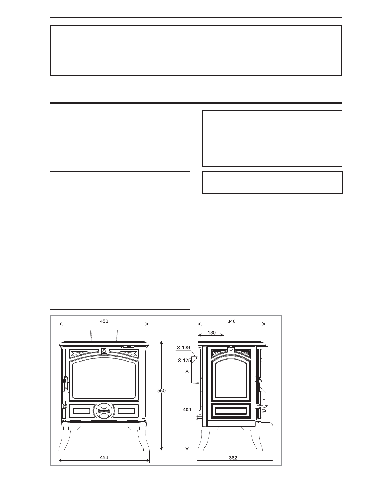
Figure 1 - Dimensions in mm
Fuel : WOOD
Logs dimensions
- Lenght maxi. . . . . . . . . . . . cm 32
Number of logs . . . . . . . . . . . . . . 2
Interval ol charge . . . . . . . . . . . mn 60
Fuel load. . . . . . . . . . . . . . . . kg 0,6
Interval ol charge . . . . . . . . . . . mn 60
2. Installation instructions
2.1. Warning to the user
All the local and national
regulations, and in particular
those relating to national and
European standards, must be
observed when installing the
appliance.
An incorrectly installed
heating appliance can cause
serious accidents (chimney
fires, burning of plastic
insulation materials, in partition
walls, etc.).
The insulation of both the
appliance and the exhaust gas
pipe has to be reinforced and
done according to the Standards
and the Building Regulations for
safety reasons. The installation
must be carried out according to
the Standards and the Building Regulations.
Failure to respect the mounting instructions leads to
engage the responsibility of the one doing the
installation.
The manufacturer’s responsibility shall be limited to the
supply of the appliance.
2.2. Location of the unit
Ventilation :
For satisfactory appliance operation with a natural
draught, check that sufficient air for combustion is
available in the room.
in houses equipped with one VMC (controlled
mechanical ventilation), this one aspire and renew the
ambient air ; In this case, the residence is under slight
low pressure and a non-sealable external air intake
must be installed in addition to the chimney itself, at
least 50cm² in section.
Position of the unit :
For new installations, select a central position within the
house, to provide a good heat distribution around the
building.
The heat distribution towards the other rooms will be
made through the communicating doors.
These rooms must be in negative pressure or must
include ventilation gratings.
Floor and walls :
Make sure that the floor can support the weight of the
appliance, its surroundings and the hood. In the
contrary the floorneeds to be reinforced with a concrete
screed to distribute this load.
Make sure they are not combustible or covered with
combustible material (as per the Building regulations).
Otherwise it must necessary to install a
non-combustible protection.
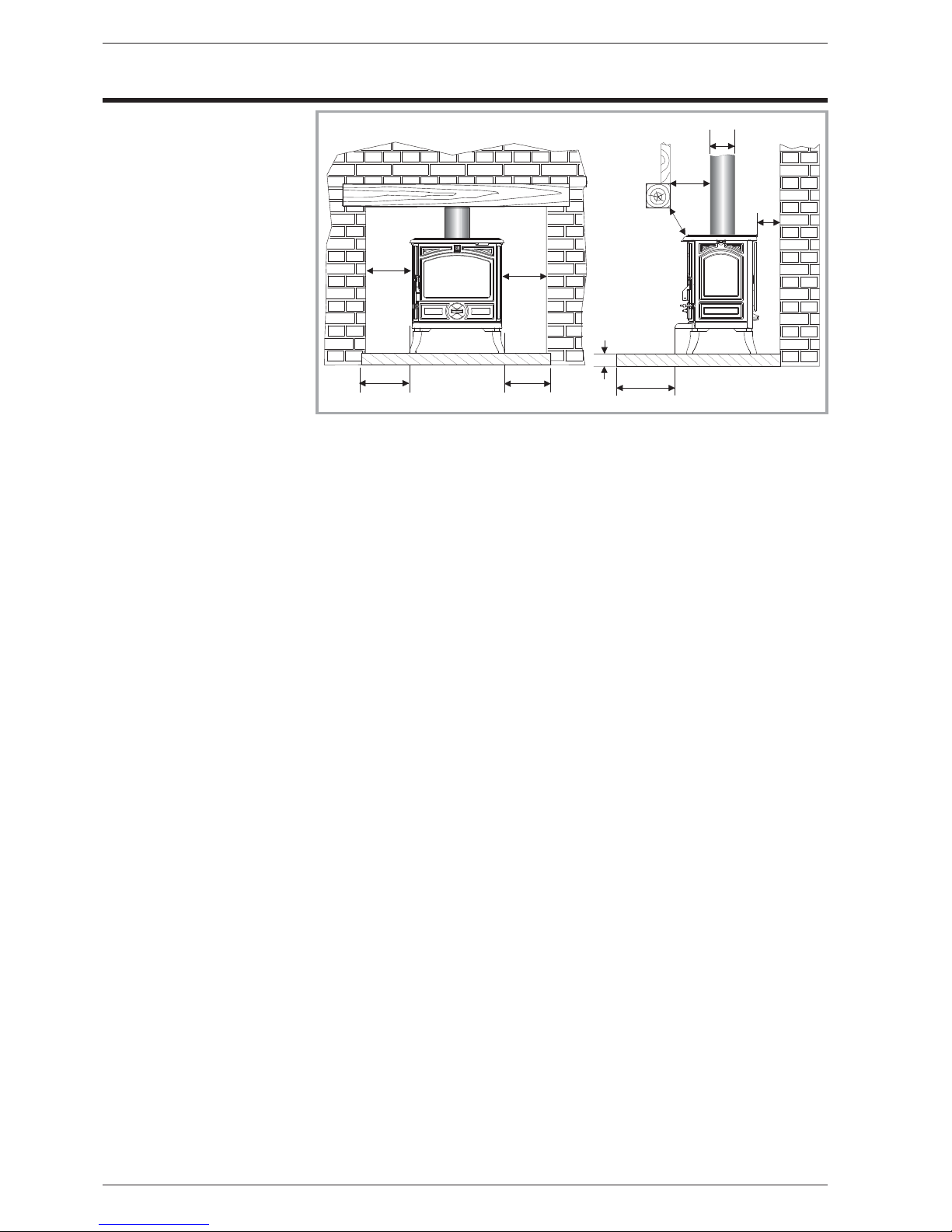
There must be a clearance of at least 150 mm at each
side of the appliance and at the back of the appliance
from a non-combustible wall.
This measurement may be reduced to a minimum gap
of 50 mm when the non-combustible wall is at least
200 mm thick.
This distance must be extended to a minimum
clearance of 425 mm from any combustible materials.
When using a single wall flue pipe, there must be a
clearance (A) of at least three times its diameter (B)
from any combustible materials.
If the appliance has to be located in an opening, this
distance must be extended to a minimum clearance (A)
of 375 mm from the pipe or the stove body to any
combustible materials.
Hearth :
The appliance must stand on a fireproof hearth.
It is possible to provide a hearth made of non
combusible board/sheet material or tiles at least 12 mm
thick (C).
Constructional hearths should be constructed of solid
non combustible material at least 125 mm thick
(including the thickness of any non combustible floor
under the hearth).
The hearth must protrude at least 225 mm in front of the
stove and 150 mm each side.
If the hearth is constructed on timber, there must be a
clearance of at least 250 mm from the timber to the top
surface of the hearth. See section J of the Building
regulations.
2.3. Flue
Existing flue :The chimney must comply with Current
Building Regulations. If in doubt, consult your Dealer or
local Building Inspector.
-
The flue must be in good condition and must provide
sufficient draught.
-
The flue must be suitable for the installation of solid
fuel burning appliances and comply with Current
Building Regulations.
-
The flue must be clean. It should be swept to remove
soot and dislodge tar deposits.
-
The flue must be well insulated. If the flue inner wall
surfaces are cold, a good thermal draw is impossible
causing condensation problems (tar formation etc) to
occur.
-
The flue must not be shared with other appliances.
4 Technical manual “1171”
“MONTFORT” - ref. 134 05 01 Installation instructions
1 5 0
1 5 0
1 5 0
3 0 0
1 5 0
B
A
A
C
1 5 0
Figure 2 - Clearances
-
The chimney must be at least 4.5 m (15 ft high).
-
In case of a flat roof or when the roof gradient is lower
than 15°, the stack must be1,2 m (4 feet) high at least.
-
If the chimney has any down draught tendency, due to
its position in relation to nearby obstacles, then an
anti-down draught cowl must be installed on the
chimney or the chimney height must be increased.
-
If the decompression in the chimney is excessive, a
draught stabiliser must be installed.
Chimney to be built / New flue : The chimney must
comply with Current Building Regulations. If in doubt,
consult your Dealer or local Building Inspector.
-
The appliance must not supportthe weight of the flue.
-
It must be distant from any combustible material
(walls, cross members)
-
It must permit an easy sweeping.
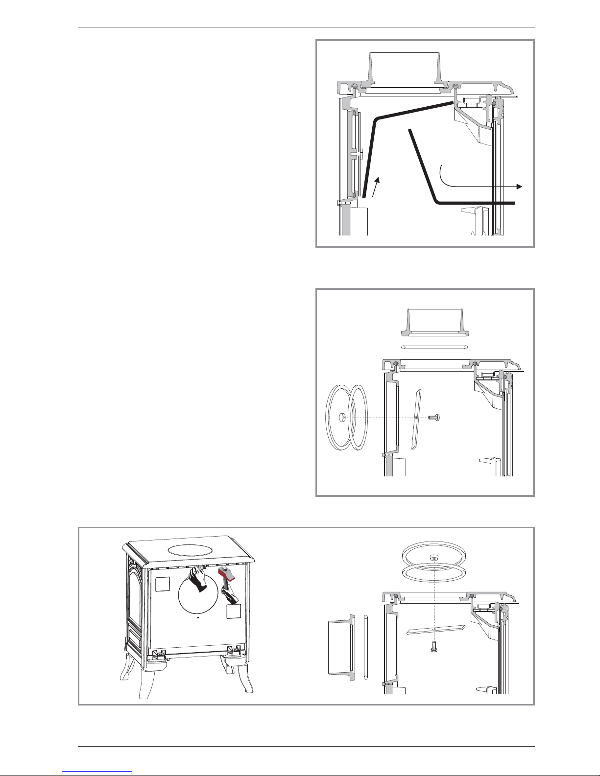
2.4. Assembly of flue collar
The stove is supplied with a connection flue spigot with
an inner diameter of 125 mm and an outer diameter of
139 mm.
2.4.1. Smoke exit on the top (figure 4)
•
Remove the internal baffle (fig. 3).
•
Fit the sealing rope in the groove on the top and fix the
flue collar with the bolts and washers supplied.
• Replace the internal baffle.
2.4.2. Smoke exit at rear (figure 5)
• Remove the internal baffle (fig. 3) and the rear heat
shield.
• Remove the clamp and the blanking plate fixed to the
back wall and replace it on the top.
•
Fix the flue collar at rear with the bolts and washers
supplied, ensuring there is a good seal.
•
Replace the internal baffle.
•
Remove the cut-out in the rear heat shield and re-fit.
Technical manual “1171” 5
“MONTFORT” - ref. 134 05 01 Installation instructions
Figure 3 - Removing the flue baffle
Figure 4 - Smoke exit on the top
Figure 5 - Smoke exit at rear
 Loading...