

Franco Belges Le Continental 174 07 53 Technical Manual
Technical manual
to be saved
by th e user
for future reference
Document n° 952-3 EN ~ 02/03/2000
Les FonderiesFranco-B el ges
59660 MERVILLE
Phone : 03.28.43.43.43
Fax : 03.28.43.43.99
RC Hazebrouck 445750565B
Subject to modifications
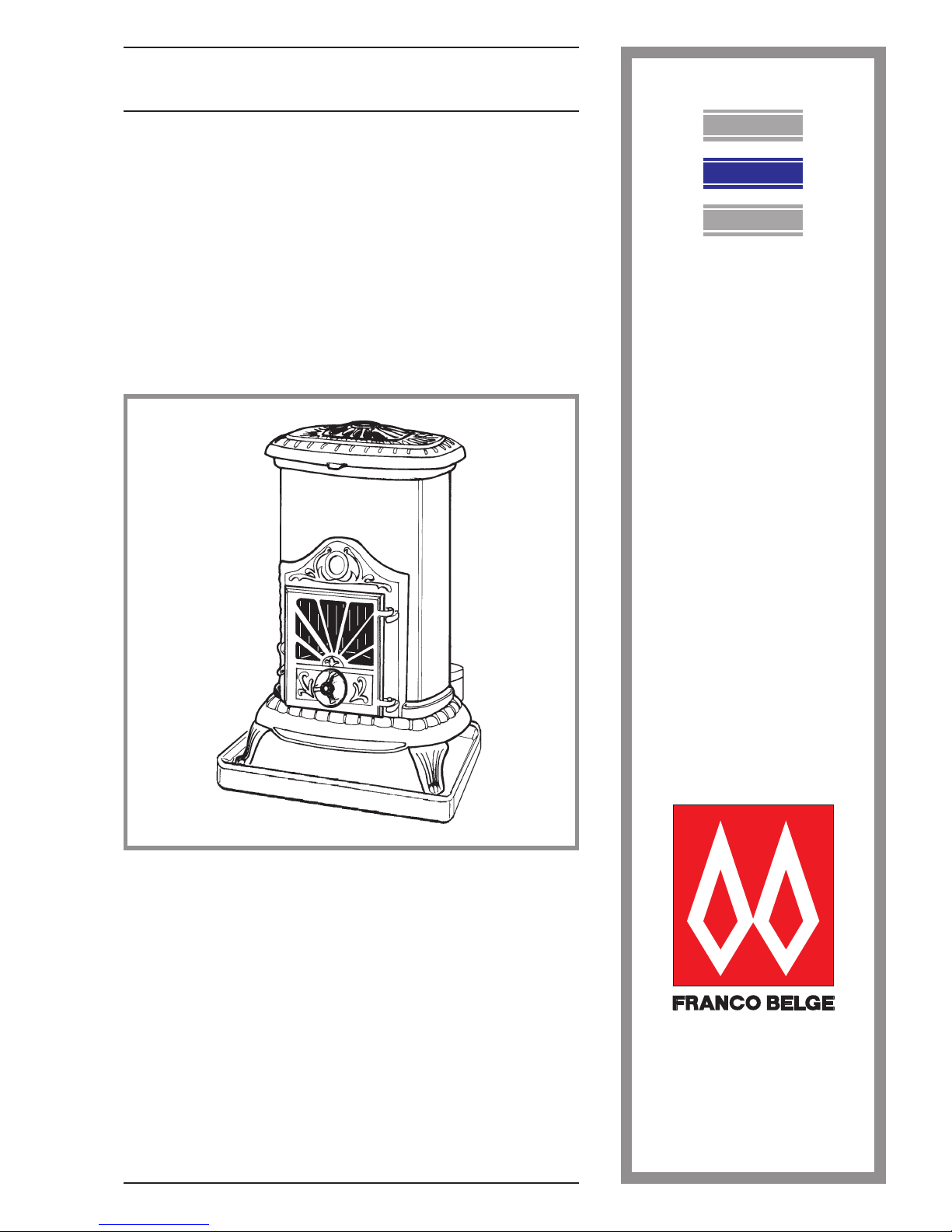
Le Continental
Oil fired stove
Model 174 07 53
(ANSI/UL & CAN/CSA approved)
Français
English
Description of the appli ance
Installation instructions
Operating instructions
Spare parts
Warranty certificate
Norsk

Descriptionoftheunit ........................................3
Description...................3
Optionalequipment..............3
Specifications.................3
Operatingprinciple..............4
Installationinstructions .......................................4
Positionoftheunit ..............4
Chimney....................4
Chimneyconnector..............4
Connection to a L.VENT chimney ......4
Pre-utilisation check .............5
Mounting the levelling feet ..........5
Levelling ....................5
Externaltank .................5
Oilflowadjustment..............6
Chimneydraught ...............6
Maintenance of the Chimney .........6
Operatinginstructions........................................6
Fuel ......................6
Lighting procedure ..............6
Operatingprocedure .............7
Shuttingdown.................7
Recommendation...............7
Maintenance of the stove ..........7
Troubleshooting ...............8
Spareparts...............................................9
CONTENTS Page Page
FRANCO BELGE congratulates you on your choice.
FRANCO BELGE, which has been granted the ISO 90 01 certification, guarantees the quality of its
appliances and is committed to meet its customers’ needs.
FRANCO BELGE, which can boast a 75-year experience in the industry of heating devices, uses
state-of-the-art technologies to design and manufacture its whole range of products.
This document contains instructions on how to install your appliance and and make full use of its
functions, both for your comfort and safety.
Document n° 952-3 EN ~02/03/2000
Continental Poêle à combustible liquide
2 Notice de référence
1.Description of the unit
1.1.Description
Flued oil stove with vaporizing burner (Norm EN1)
1.2.Optional equipment
¤ Ground vat
1.3.Specifications
Nominal Heat Output(NF D 35.001) . . . kW 6,5
...................... Btu/hr 26.000
Oil consumption at :
- maximum speed . . . . . . . . . . . . . . l/h 0,81
.......................gal/hr 0,22
- minimum speed . . . . . . . . . . . . . . l/h 0,25
.......................gal/hr 0,066
Chimney draft required at :
- maximum speed . . . . . . . . . . . . . . Pa 15
- minimum speed . . . . . . . . . . . . . . Pa 6
Weight .................... kg 55
USA/CANADA - Connectionto a L.VENTchimney :
Nominal heat output . . . . . . . . . . . Btu/h 19 600
........................kW 5.75
Oil consumption at nominal speed . USgal/h 0.198
........................ l/h 0.75
Chimneydraft.............. “w.c.g 0.06
........................ Pa 15
7
9
8
1
2
3
4
5
6
10
11
12
13
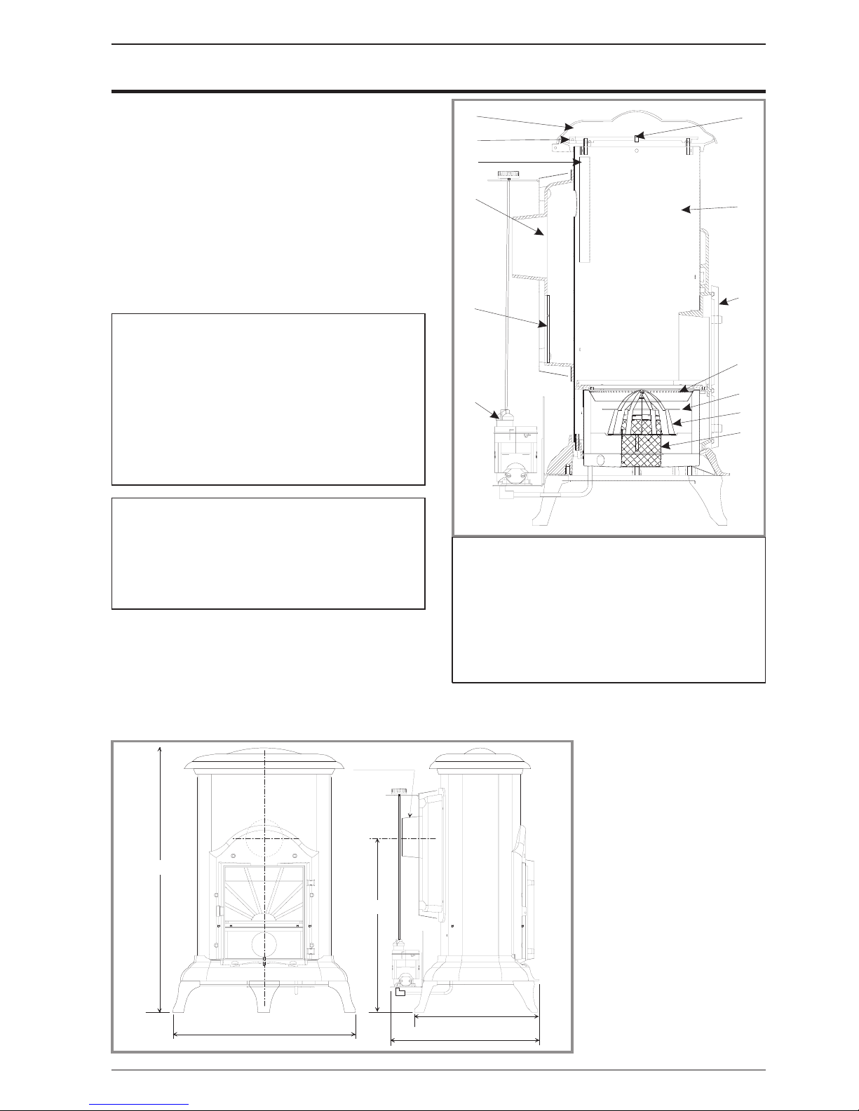
Fig. 1 - Description
1 - Cover
2-Topplate
3 - Flue baffle
4 - Flue box
5 - Draught regulator
6 - Carburettor
7 - Draught control
8 - Combustion chamber
9 - Main door
10 - Catalyser ring
11 - Catalyser cover
12 - Catalyser body
13 - Air inlet holes
540
460
Ø 120 / 127
805
530
350
805 mm - 31 3/4"
Ø 120 / 127 mm - Ø 5"
540 mm - 21 1/4"
530 mm - 20 4/5"
350 mm - 13 3/4"
460 mm - 18"
Fig. 2 - Dimensions in mm
Document n° 952-3 EN ~ 02/03/2000
Continental Poêleà combustible liquide
Notice de référence 3
1.4. Operating principle
Furnace oil is fed to the burner floor (fig. 1) where is it
ignited by means of a firestarter. The heat produced by
this flame brings the burnertemperature to the required
level to vaporize the fuel. Oil will only burn as a vapour
not a liquid.
Room combustion air enters the burner through the air
inlet holes (# 13, fig. 1).
In the center of the burner is the catalyser (# 12, fig. 1)
which aids in vaporizing the fuel. When the stove is
operation,the catalyser glows red. The stove should not
be used wi th out both the catalyser (# 12, fig. 1),
catalyser top (# 11) and ring (# 10).
A de-scaling lever (#1, fig.8) can be pushed and pulled
inandout aswell asturningslightlyat thesametimeto
keep the inlet pipe clear of carbon buildup.
The stove float regulator contains a filter to trap
impurities.
A safety lever controls fuel flow. Oil can only enter the
float chamber when the safety lever is depressed.
Oil temperature variations willaffect theoil flow intothe
float chamber. A float in the chamber raises the fuel
level available to the burner.
The carburetor is also controlled by a control knob
which turns from “0" (off) to ”6" (high setting).
A draft regulator (# 3, fig. 7) ensures a constant air
intake to the burner regardless of external factors.
2.Installation instructions
USA / CANADA : Theinstallation of this stove must com-
ply with state and local requirements and the standard
CSA B139.
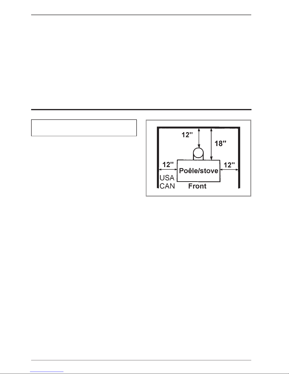
2.1.Position of the unit
- The position of the appliance must be chosen very
carefully in order to obtain the best possible results for
heat distribution.
- Position the unit to comply with the minimum
clearances to co mbustible material. M inimum
clearances are shown from the vertical portion of the
chimney connector. Check that no overhead cross
members in the ceiling will be cut. Reposition unit if
necessary, being careful not to move closer than the
minimum clearances.
- Outside air : For the oil stove to function properly, an
adequate supply of combustion air is required.
2.2. Chimney
- Ensure that the flue has sufficient draught (refer to
technical details).
- Minimum flue diameter, 10 cm (4" I.D).
- The chimney must be at least 4.5 m (15 ft high).
- The flue must not be shared with anyother appliance.
- Do wndraughts caused by obstacles close to the
chimney top may sometimes be prevented by fitting an
anti-downdraught cap to the top of the chimney.
- The chimney must have a constant cross section. Too
large a flue could affect the chimney draught.
- The chimney must be soundly constructed,in order to
prevent cold air infiltration.
- The flue must be well insulated, water and air tight. A
chimney with a coldinternalsurface can prevent a good
chimney drau ghtand condensation will occur.
-The flue must be swept at least once a year.
2.3.Chimney connector
- The appliance must be as close as possible to the
chimney. Avoid horizontal flue connection pipes which
can dangerously restrain functioning of the appliance.
The connector pipe should bestandard black paintedor
blued steel pipe of not less than 30 gage; 304 grade
stainless steel of not less than 30 gage; or 1 mm
viterous enamelled steel, with a maximum diameter of
5 inch O.D. - (127mm). It isthe installer’sresponsability
to conform to local building standards and requirements
with regard to installation.
Single wall pipe may be utilized being careful to
maintain clearances to any combustible surface.(fig. 3)
Once the stove hasbeen properly installedthe chimney
draught must be checked with a draught meter.
If the chimney draught is excessive or irregular, a
draught stabilizer (barometric damper) must be
installed to the connector pipe.
2.4.Connection to a L.VENT chimney
USA / Canada
: The 174 07 53 appliance is certifiedto
be connected to a 5" L.VENT chimney with its nominal
heatoutputlimitedto 19600 Btu/h (5.75 kw) .This will be
achieved by replacing the float-regulator (carburator)
(# 19 fig. 9).Please contact your dealer to have this
alteration done.
WARNING. FRANCO-BELGE is not responsible for
any incidental or consequential damages if this
operation is not done.
Figure 3 - Minimum clearances to combustible surfaces
Document n° 952-3 EN ~02/03/2000
Continental Poêle à combustible liquide
4 Notice de référence
 Loading...