

FRANCO BELGE The Belfort 54 05 06 Technical Manual
Technical manual
to be saved
by the user
for future reference
Document n° 963-3 ~ 17/05/2001
Les Fonderies Franco-Belges
59660 MERVILLE
Phone : 03.28.43.43.43
Fax : 03.28.43.43.99
RC Hazebrouck 445750565B
Subject to modifications
The Belfort
Balanced flue Gas stove
EN 613.
Model : 154 05 06
Natural gas (type G20)
Type : I
2E+ (FR) /I2H (GB).
Réf. : 154 05 07
Propane (type G31)
Type : I
3P.
Description of the appliance
Installation instructions
Operating instructions
Spare parts
Warranty certificate
Français
English

Product information . . . . . . . . . . . . . . . . . . . . . . . . . . . . . . . . . . . . . . 3
Package . . . . . . . . . . . . . . . . . . 3
General characteristics . . . . . . . . . . 3
Description . . . . . . . . . . . . . . . . . 4
Installation instructions . . . . . . . . . . . . . . . . . . . . . . . . . . . . . . . . . . . . 5
Siting the appliance . . . . . . . . . . . . 5
Flue connection . . . . . . . . . . . . . . 6
Ventilation (G.B. Only) . . . . . . . . . . 7
Connecting the gas supply . . . . . . . . 7
Pressure testing . . . . . . . . . . . . . . 7
Coals layout . . . . . . . . . . . . . . . . 8
Service section . . . . . . . . . . . . . . . 9
User instructions . . . . . . . . . . . . . . . . . . . . . . . . . . . . . . . . . . . . . . . . 10
Important Notes . . . . . . . . . . . . . . 10
Data information . . . . . . . . . . . . . . 10
Operating the stove . . . . . . . . . . . . 10
Safety mechanisms . . . . . . . . . . . 11
Cleaning . . . . . . . . . . . . . . . . . 11
Servicing . . . . . . . . . . . . . . . . . 11
Spare parts . . . . . . . . . . . . . . . . . . . . . . . . . . . . . . . . . . . . . . . . . . . 12
CONTENTS Page Page
FRANCO BELGE congratulates you on your choice.
FRANCO BELGE, which has been granted the ISO 9001 certification, guarantees the
quality of its appliances and is committed to meet its customers needs.
FRANCO BELGE, which can boast a 75-year experience in the industry of heating devices,
uses state-of-the-art technologies
to design and manufacture its whole range of products.
Balanced flue Gas stove Model. 154 05 06 / 154 05 07

WARNING
The appliance must be installed in compliance with Current Building Regulations.
Incorrectly installed, this appliance can be dangerous
and possibly cause serious accidents.
The manufacturers responsibility shall be limited to the supply of the equipment.
❑
1.Product information
1.1. Package
•1 package : Stove complete.
The ceramic coals are supplied inside the combustion
chamber.
•1 package : Balanced flue
1.2.Optional equipment
Balanced flue elbow 135° (code 72630).
1.3.
General characteristics
Model . . . . . . . . . . . . . . . . . . . . . . . . . . . . . . . . . . . . . 154 05 06 . . . . . . . 154 05 07
GAS . . . . . . . . . . . . . . . . . . . . . . . . . . . . . . . . . . . . . Natural gas . . . . . Propane LPG
Type/category . . . . . . . . . . . . . . . . . . . . . . . . . . . . . . . . . G20 / I
2H
. . . . . . . G31 / I3P
Gross calorific value (heat input) . . . . . . . . . . . . . kW . . . . . . . . . 4.2 . . . . . . . . . . 3.9
Nominal output . . . . . . . . . . . . . . . . . . . . . . . kW . . . . . . . . . 3 . . . . . . . . . . . 3
Supply pressure . . . . . . . . . . . . . . . . . . . . . mbar . . . . . . . . . 20 . . . . . . . . . . . 37
Burner pressure . . . . . . . . . . . . . . . . . . . . . mbar . . . . . . . . 18,5 . . . . . . . . . 35,5
Gas rate . . . . . . . . . . . . . . . . . . . . . . . . . m
3
/h . . . . . . . . 0,44 . . . . . . . . . 0,16
Injector size . . . . . . . . . . . . . . . . . . . . . . . bray . . . . . . . 18 / 280 . . . . . . . 18 / 120
Weight . . . . . . . . . . . . . . . . . . . . . . . . . . . Kg . . . . . . . . . 55 . . . . . . . . . . . 55
420
550
409
398
Ø 153
Figure 1 - Dimensions in mm
Model. 154 05 06 / 154 05 07 Balanced flue Gas stove
Technical manual 3
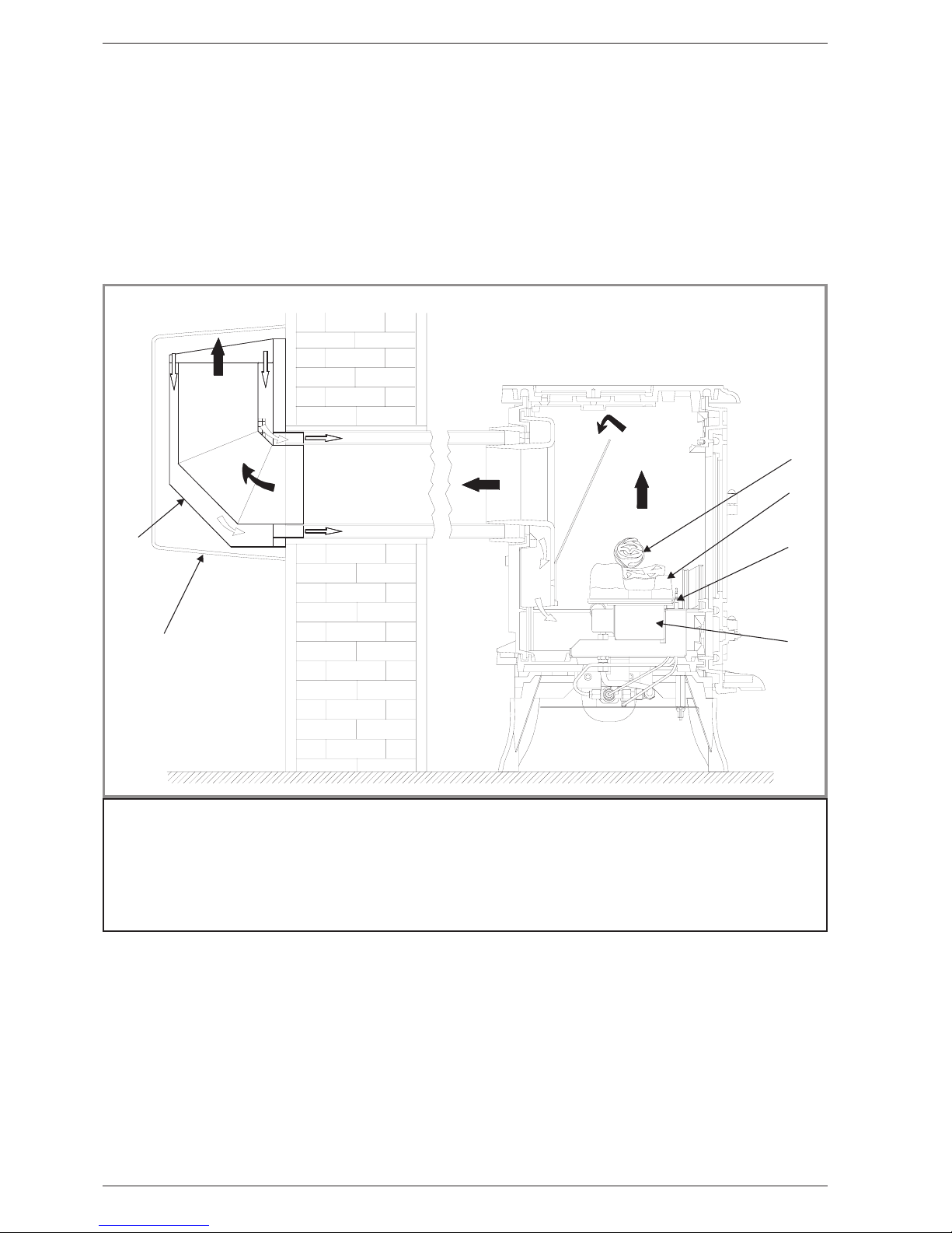
1.4. Description
The Belfort balanced flue stove has been individually
designed to add traditional charm and character to your
home. Providing a highly efficient heat source, the
appliance has the look and charm of a ‘real’ stove
coupled with the convenience of clean burning gas.
The stove is designed to run off Natural or LPG gas. It
is important to note that once a type of gas has been
specified the stove cannot run off any other type. The
type of gas that your stove is capable of burning is
stated on the data information panel under the stove.
The appliance is a “Balanced flue gas stove”, which is
a term used to describe a sealed combustion system in
which the inlet air and exhaust gases enter and exit
through two separate concentric passageways within
thesamesealedventsystem.
The Balanced flue system allows the gas appliance to
be vented directly to the outside atmosphere through a
suitable outside wall, unlike conventional venting
systems that take the inlet air from the room and vent
the exhaust vertically through the roof to the
atmosphere.
1
2
3
4
5
6
7
3
8
Figure 2 - Description
1 : Balenced flue
2 : Flue outlet
3 : Air inlet
4 : Ceramic coals
5 : Coals support
6 : Pilot
7 : Burner
8 : Protective grate
Balanced flue Gas stove Model. 154 05 06 / 154 05 07
4 Technical manual
2.Installation instructions
This balanced flue gas stove is designed to run on
either natural gas or LPG. The burner unit is not
interchangeable between gas types.
The stove is a radiant convector fuel effect stove with a
balancedfluesystem.The Belfort can be placeddirectly
inside any fireplace opening of the dimensions noted
within the installation instructions, providing it is on a
suitable outside wall.
These instructions have been compiled in accordance
with EN 613 1995.
It is required by law that any appliance using natural or
LPG gas is installed by a competent person (e.g.
CORGI registe red), in conjunction with these
instructions and the requirements as laid down in the
following Regulations and British Standards :
- The Gas safety (Installation and Use) Regulations
1994 amended 1996.
- The Building Regulations (issued by the department of
the Environment).
- The Building Standards (Scotland) (Consolidation)
Regulations.
APPLIANCE TO BE INSTALLED IN ACCORDANCE
TO NATIONAL & LOCAL REGULATIONS.
Ensure that the s tove corresponds to the type of gas
withwhichitistobeused.Thiscanbeconfirmedby
checking the data badge located underneath the
appliance.
All surfaces except the control knob are considered to
be working surfaces.
2.1.Siting the appliance
Theappliancemustbesitednext to an adjacent exterior
wall.
The gas supply connection to the appliance is at the
rear right hand side. The connection requires 8 mm
diameter semi-rigid pipe, not more than 1 metre in
length.
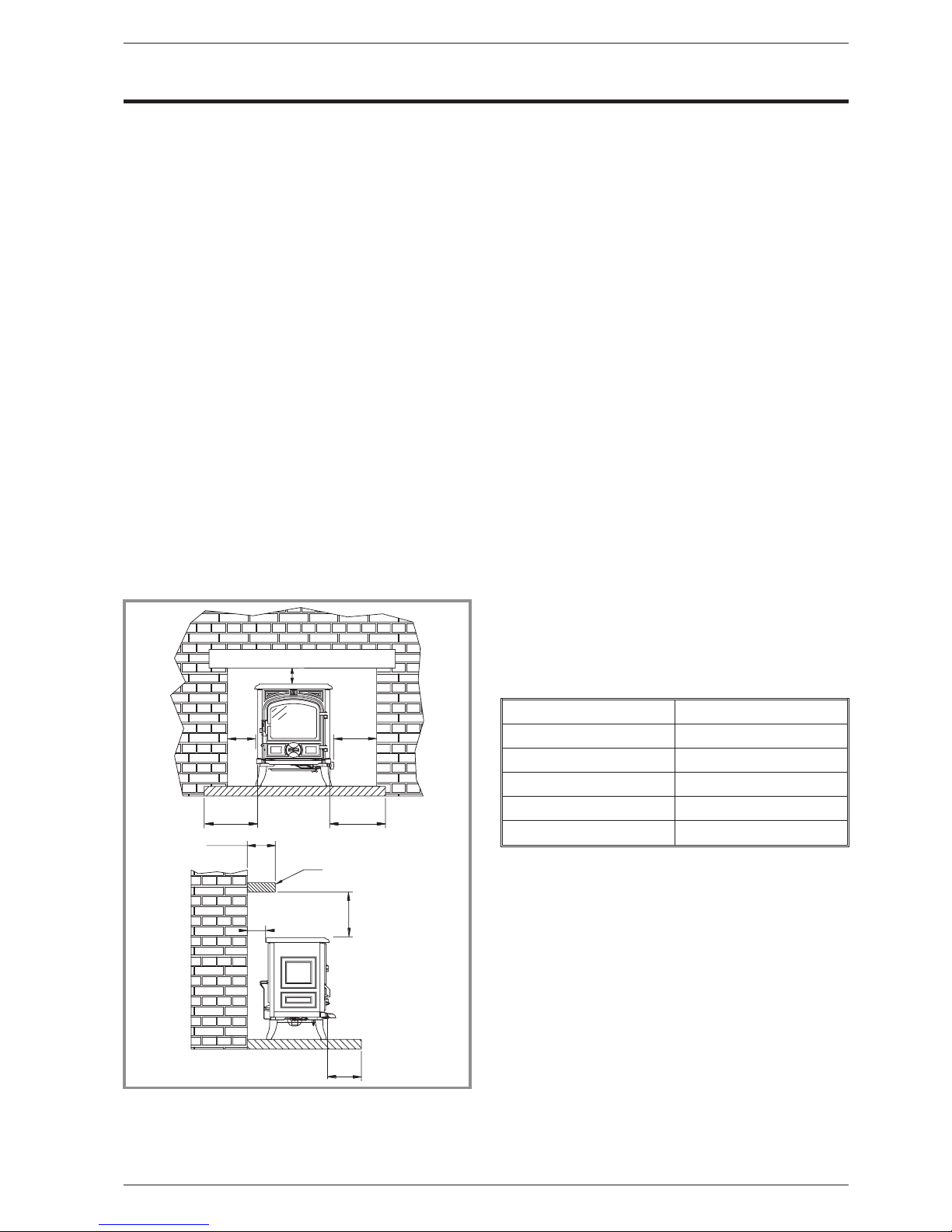
2.1.1. Clearance requirements
If the appliance has to be located in an opening, there
must be a clearance of at least 50 mm at the left hand
of the appliance, 50 mm at the back of the appliance
and 50 mm above from any non-combustible materials
(as shown in figure 3).
This distancemustbe extendedtoamininumclearance
of 80 mm from any combustible materials.
There should ideally be a minimum gap of 150 mm at
the right hand side of the stove (this will ensure the best
possibleaccesstothecontrolknob). This measurement
may be reduced to a minimum gap of 100 mm if needed
however extra care should be taken when operating the
control knob when the appliance is hot.
A combustible shelf may be fitted over the appliance,
providedthatinthe case of a 150 mmorlessdeepshelf,
there is at least 250 mm clearance above the top of the
stove. The shelf depth may increase at the same rate
as the increase in clearance ; i.e. a shelf depth of
200 mm would require a clearance of 300 mm.
AB
100 250
150 250
200 300
250 350
300 400
2.1.2. Hearth
The stove must stand on a fireproof hearth.
To comply with the Building Regulations issued by the
Department of the Environment, the following points
should be noted when choosing a hearth :
a - The hearth mu st be made of non-combustible
material of thickness 12 mm minimum.
b - The hearthmust protrude at least 150 mm in front of
the stove and 150 mm each side.
c - The hearth must not be capable of inadvertent
covering by a carpet or rug. This should be achieved by
either :
- the hearth being 50 mm above the level of the room
floor.
- a fender or kerb around the edge of the hearth to a
height of at least 50 mm above the floor.
1 5 0
1 5 0
1 5 0
5 0
n o n - c o m b u s t i b l e = 1 0 0
1 0 0
5 0
D E P T H
A *
c o m b u s t i b l e = B *
S h e l f
5 0
Figure 3
Minimum clearances to non-combustible materials,
hearth and shelf (in mm)
Model. 154 05 06 / 154 05 07 Balanced flue Gas stove
Technical manual 5
 Loading...