

FRANCO BELGE Savoy Classic 134 08 05 Technical Manual
Description of the ap pliance
Installation instructions
Operating instructions
Spare parts
Warranty certificate
Document n° 986-11 ~ 03/12/2007
STAUB FONDERIE
Head Office Address
2, rue Saint Gilles
68230 TURCKHEIM
RCS Colmar
SIREN 444 881 953
Address
Administration and manufacturing
BP 73
59660 MERVILLE (FRANCE)
Telephone : 00 333 28 43 43 00
Fax : 00 333 28 43 43 99
Subject to modifications.
SAVOY Classic
Multifuel stove
Model : 134 08 05
DIN EN 13240 : 2005-10
Net output : 7,7 kW (Wood)
Net output : 6,4 kW (Smokeless fuels)
Technical manual
to be saved
by the user
for future reference
SARL with the capital of 10 000 000 €
2 Technical manual “986”
“Savoy” - ref. 134 08 05
CONTENTS
Product information ·······················································p.3
Package ..........................p.3
General characteristics ..............p.3
Description ........................p.3
Principle of operation ...............p.3
Installation instructions····················································p.4
Warning to the user .................p.4
Location of the unit .................p.4
Chimney ..........................p.4
Assembly of flue collar ..............p.5
Chimney connector .................p.5
Mounting the tray...................p.6
Pre-utilisation check ................p.6
Door closing pressure ...............p.6
Maintenance of the Chimney .........p.7
Instructions for user·······················································p.8
Fuel..............................p.8
Instruction for use with wood .........p.9
Instructions for use with solid fuel .....p.9
Cleaning ..........................p.9
Maintenance of the Chimney .........p.9
Maintenance of the stove body........p.9
Recommendations..................p.9
Trouble Shooting ..................p.10
Spare parts······························································p.11
FRANCO BELGE congratulates you on your choice.
FRANCO BELGE, guarantees the quality of its appliances and is committed to meet its
customers’ needs.
FRANCO BELGE, which can boast a 80-year experience in the industry of heating devices, uses
state-of-the-art technologies
to design and manufacture its whole range of products.
This document contains instructions on how to install your appliance and make full use of its
functions, both for your comfort and safety.
This appliance is meant to burn wood and smokeless fuels safely
WARNING
Incorrectly installed, this appliance can be dangerous and possibly cause serious accidents.
We recommend that you engage the services of a professional engineer for its installation
and the regular maintenance requirements.
1. Product information
1.1. Package
•
1 package : Stove complete.
1.2. General characteristics
Reference ................ 1340805
FUEL : WOOD
Chimney draught required ......Pa 12
Volume heated ............m
3
280
Usable firebox dimensions
- width ................mm 450
- depth ................mm 240
- height ................mm 365
Log dimensions
- Lenght maxi .............cm 40
Ash pan capacity ..........litres 3
Net weight ...............kg 100
Flue gas temperature .........°C 341
Nominal output ............kW 7,7
Efficiency................% 72,6
Co (13% O
2
)..............% 0,42
Flue gas mass flow ..........g/s 7
Fuel rate ...............kg/h 2,4
Refuelling interval ..........mn 102
FUEL : ANTHRACITE (SMOKELESS FUELS)
Tested with fuel brand name “phurnacite” entering in
category A, table B2 frpm the standard EN 13240.
Nominal heat output .........KW 6,4
Chimney draught required ......Pa 18
Flue gas temperature .........°C 165
Efficiency................% 73
Co (13% O2) ..............% 0,5
Fuel rate ...............kg/h 0,8
Refuelling interval ..........mn 132
1.3. Description
•
Multifuel stove in conformity with DIN EN 13240 :
2005-10
•
Intermittent-burning heating appliance wood and
smokeless fuels.
•
Fuel burnt on grate
•
Enclosed combustion chamber with refractory brick
walls.
•
Removable appliance, to be installed near a wall.
•
Detachable flue spigot for rear or top chimney
connection.
•
Detachable top for easy handling and cleaning (rear
smoke exit only).
•
Adjustable air controls for controlling the burning rate.
•
Spin wheel for lighting.
•
Large ash-pan.
1.4. Principle of
operation
The appliance is
designed for operation
with the door closed.
Heat is mainly diffused by
radiation, through the
window and body of the
appliance.
Combustion occurs on
the grate, with draught
entry through the top of
the combustion chamber
when using wood and
under the grate when
using smokeless fuels.
Technical manual “986” 3
“Savoy” - ref. 134 08 05 Product information
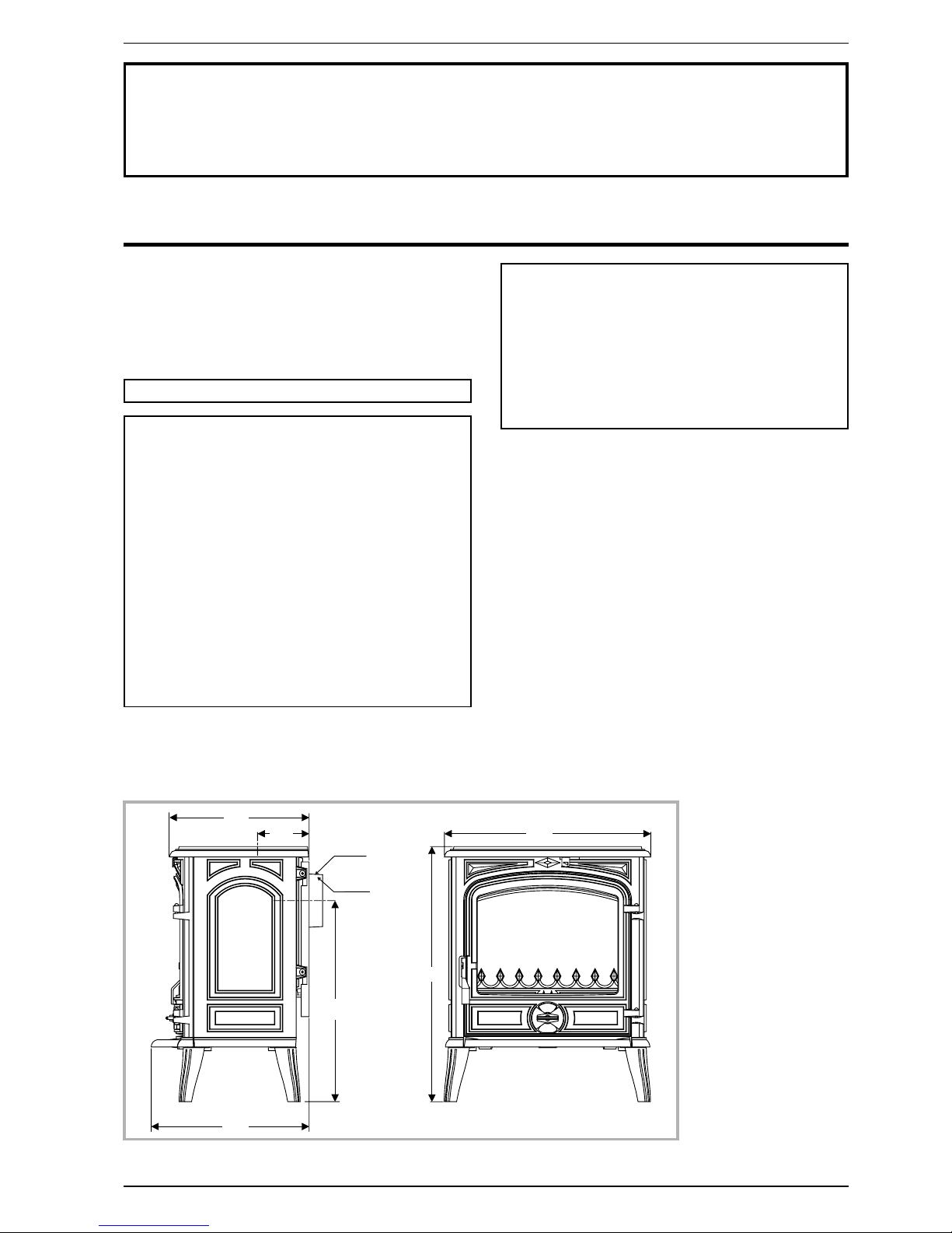
6 6 0
1 3 4
5 2 0
4 0 9
5 3 5
Ø 1 2 5
Ø 1 3 9
3 6 0
Figure 1 - Dimensions in mm
2. Installation instructions
2.1. Warning to the user
All the local and national regulations, and in
particular those relating to national and European
standards, must be observed when installing the
appliance.
An incorrectly installed heating appliance can
cause serious accidents (chimney fires, burning of
plastic insulation materials, in partition walls, etc.).
The insulation of both the appliance and the
exhaust gas pipe has to be reinforced and done
according to the Standards and the Building
Regulations for safety reasons.
Failure to respect the mounting instructions leads to
engage the responsibility of the one doing the
installation.
The manufacturer’s responsibility shall be limited to the
supply of the equipment.
2.2. Location of the unit
Ventilation :
For satisfactory appliance operation with a natural
draught, check that sufficient air for combustion is
available in the room.
Position of the unit :
For new installations, select a central position within the
house, to provide a good heat distribution around the
building.
The heat distribution towards the other rooms will be
made through the communicating doors.
These rooms must be in negative pressure or must
include ventilation gratings.
Floor and walls :
Make sure they are not combustible or covered with
combustible material (as per the Building regulations).
Otherwise it must necessary to install a
non-combustible protection.
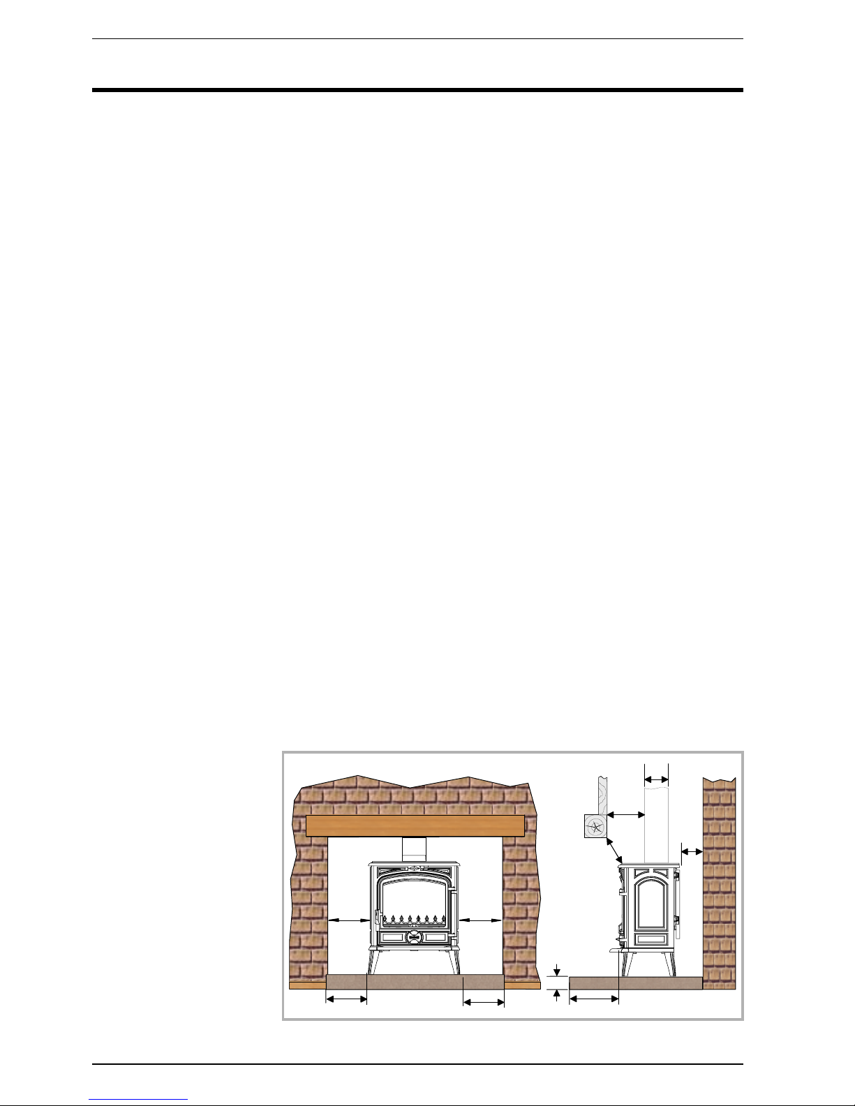
There must be a clearance of at least 150 mm at each
side of the appliance and at the back of the appliance
from a non-combustible wall.
This distance must be
extended to a minimum
clearance of 350 mm from any
combustible materials.
This measurement may be
reduced to a minimum gap of
50 mm when the
non-combustible wall is at
least 200 mm thick.
When using a single wall flue
pipe, there must be a
clearance (A) of at least three
times its diameter (B) from
any combustible materials.
If the appliance has to be
located in an opening, this
distance must be extended to
a minimum clearance (A) of
375 mm from the pipe or the
stove body to any combustible
materials.
Hearth :
The appliance must stand on a fireproof hearth.
It is possible to provide a hearth made of non
combusible board/sheet material or tiles at least 12 mm
thick.
Constructional hearths should be constructed of solid
non combustible material at least 125 mm thick
(including the thickness of any non combustible floor
under the hearth).
The hearth must protrude at least 225 mm in front of the
stove and 150 mm each side.
If the hearth is constructed on timber, there must be a
clearance of at least 250 mm from the timber to the top
surface of the hearth.
See section J of the Building regulations.
2.3. Chimney
The chimney must comply with Current Building
Regulations. If in doubt, consult your Dealer or local
Building Inspector.
Existing flue :
-
The flue must be suitable for the installation of fuel
burning appliances, otherwise it must necessary to
install a tubing
-
The flue must be in good condition and must provide
sufficient draught (refer to technical details p. 3 ).
-
The flue must be clean. It should be swept to remove
soot and dislodge tar deposits.
-
The flue must be well insulated. If the flue inner wall
surfaces are cold, a good thermal draw is impossible
causing condensation problems (tar formation etc.) to
occur.
-
The flue must be watertight.
-
The chimney must have a constant cross section.
-
The flue must not be shared with other appliances.
-
The chimney must be at least 4.5 m (15 ft high).
-
In case of a flat roof or when the roof gradient is lower
than 15°, the stack must be 1,2 m (4 feet) high at least.
-
The capping must not restrain the draught.
4 Technical manual “986”
“Savoy” - ref. 134 08 05 Installation instructions
1 5 0
1 5 0
1 5 0
3 0 0
1 5 0
B
A
A
C
1 5 0
Figure 2 - Clearances
-
If the chimney has any down draught tendency, due to
its position in relation to nearby obstacles, then an
anti-down draught cowl must be installed on the
chimney or the chimney height must be increased.
-
If the chimney draught is excessive or irregular, a
draught stabiliser (barometric damper) must be
installed to the connector pipe.
Chimney to be built / New flue:
The chimney must comply with Current Building
Regulations. If in doubt, consult your Dealer or local
Building Inspector.
-
The flue must not be supported by the stove.
-
Consult a chimney specialist for advice on suitable
flue systems for solid fuel appliances.
-
It must be distant from any combustible material
(walls, cross members)
-
It must permit an easy sweeping.
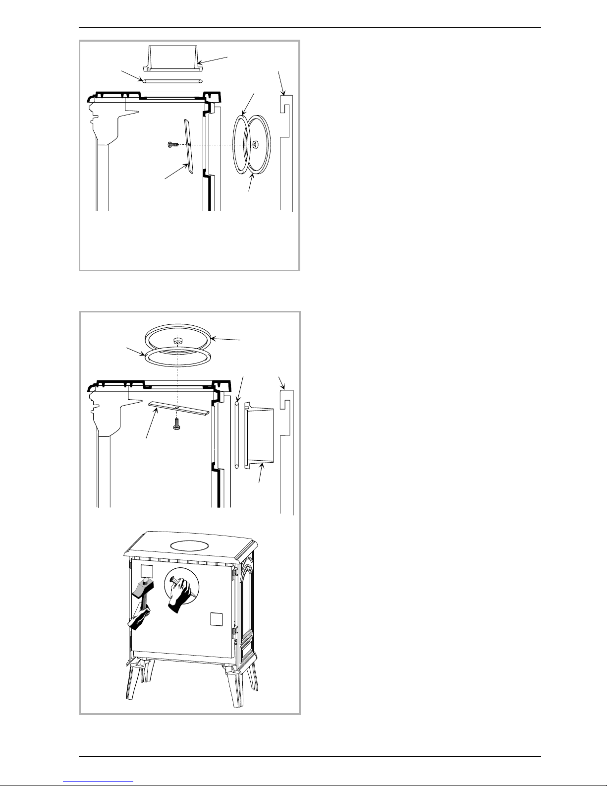
2.4. Assembly of flue collar
The stove is supplied with a connection flue collar with
an inner diameter of 125 mm and an outer diameter of
139 mm.
2.4.1. Flue outlet on the top
Figure 3
-
Remove the flue baffle (fig. 9, p. 7)
-
Fit the sealing rope 2 in the groove on the top and fix
the flue collar 1 with 3 bolts and washers supplied.
-
Replace the flue baffle
2.4.2. Flue outlet at rear
Figure 4
-
Remove the retainer fuel (fig. 8, p. 7), the two side
bricks and the flue baffle (fig. 9, p. 7).
-
Remove the rear heat shield and remove the cut-out
on it.
-
Remove the blanking plate 3 and the clamp 4 and refit
in the top, ensuring there is a good seal.
-
Fix the flue collar 1 at rear with the bolts and washers
supplied, ensuring there is a good seal.
-
Replace all the internal parts in the reverse order.
-
Replace the rear heat shield.
2.5. Chimney connector
-
The appliance must be installed as close as possible
to the chimney.
-
The connector pipe must be approved for installation
with combustion products (e.g. 316 grade 1 mm thick
stainless steel or vitreous enamelled steel).
-
Pipe diameter must not be less than the appliance
spigot diameter.
-
If there is no other solution, the reduction can not be
more than one diameter lower than the flue spigot and
be situated as distant as possible from the flue
connection of the appliance.
-
The connection can be either vertical or horizontal. For
horizontal connections, avoid right angle bends.
-
The join between the connection pipe and the
stovepipe, and the flue, must be leak tight.
Technical manual “986” 5
“Savoy” - ref. 134 08 05 Installation instructions
1
2
3
4
2
5
Figure 3 - Flue outlet on the top
1
2
3
4
2
5
Figure 4 - Rear flue outlet
1 - Flue collar
2 - Ceramic rope
3 - Blanking plate
4 - Clamp
5 - Rear heat shield
 Loading...