

FRANCO BELGE Savoie 174 08 02 Y Technical Manual
Description of the appliance
Installation instructions
Operating instructions
Spare parts
Warranty certificate
Technical manual
to be saved
by the user
for future reference
Document n° 1038-2 ~ 24/10/2001
Les Fonderies Franco-Belges
59660 MERVILLE
Phone : 03.28.43.43.43
Fax : 03.28.43.43.99
RC Hazebrouck 445750565B
Subject to modifications
SAVOIE
Oil burning stove
Model : 174 08 02 Y
(EN1)
English
Norsk
Description of the unit . . . . . . . . . . . . . . . . . . . . . . . . . . . . . . . . . . . . 3
Description . . . . . . . . . . . . . . . . . 3
Package . . . . . . . . . . . . . . . . . . 3
Optional equipment . . . . . . . . . . . . 3
Specifications . . . . . . . . . . . . . . . 3
Operating principle . . . . . . . . . . . . . 4
Installation instructions . . . . . . . . . . . . . . . . . . . . . . . . . . . . . . . . . . . . 4
Warning to the user . . . . . . . . . . . . 4
Position of the unit . . . . . . . . . . . . . 4
Chimney . . . . . . . . . . . . . . . . . . 4
Mounting the levelling feet . . . . . . . . 5
Smoke exit . . . . . . . . . . . . . . . . . 5
Chimney connector . . . . . . . . . . . . 5
Levelling . . . . . . . . . . . . . . . . . . 5
External / remote tank . . . . . . . . . . . 6
Pre-utilization check . . . . . . . . . . . . 6
Oil flow adjustment . . . . . . . . . . . . . 6
Chimney draft required . . . . . . . . . . 7
Maintenance of the Chimney . . . . . . . 7
Door closing pressure . . . . . . . . . . . 7
Removing the burner . . . . . . . . . . . 8
Instructions for user . . . . . . . . . . . . . . . . . . . . . . . . . . . . . . . . . . . . . . 8
Fuel . . . . . . . . . . . . . . . . . . . . . 8
Lighting procedure . . . . . . . . . . . . . 8
Operating procedure . . . . . . . . . . . . 9
Shutting down . . . . . . . . . . . . . . . 9
Recommendations . . . . . . . . . . . . . 9
Maintenance of the stove . . . . . . . . . 9
Trouble shooting . . . . . . . . . . . . . 10
Spare parts . . . . . . . . . . . . . . . . . . . . . . . . . . . . . . . . . . . . . . . . . . . 11
CONTENTS Page Page
FRANCO BELGE congratulates you on your choice.
FRANCO BELGE, which has been granted the ISO 9001 certification, guarantees the
quality of its appliances and is committed to meet its customers needs.
FRANCO BELGE, which can boast a 75-year experience in the industry of heating devices,
uses state-of-the-art technologies
to design and manufacture its whole range of products.
This document contains instructions on how to install your appliance and and make full
use of its functions, both for your comfort and safety.
Savoie - ref. 174 08 02 Y
2 Technical manual "1038"

This appliance is an oil-fired stove.
WARNING
An incorrectly installed oil-fired stove can cause serious accidents. This appliance
should only be installed by competent personnel.
1.Description of the unit
1.1. Description
Flued oil stove with vaporizing burner. (Norm EN1)
1.2. Package
1 package : 1 stove
1.3.Optional equipment
•Visioflamme (mirrors)
•Glow-plug ignitor
•Ground vat
•Ceramic coals
1.4. Specifications
Model ...................... 1740802
NominalHeatOutput ............kW 8
atmaximumspeed ........... liter/hr 0,95
at m inim um speed . . . . . . . . . . . . liter/hr 0,25
Chimney draft required
atmaximumspeed ............. Pa 15
atminimumspeed.............. Pa 8
Weight .................... kg 100
200 mm
200
mm
200
mm
200 mm
Figure 1 - Minimum
clearances
535
660
554
545
506
Ø 125 int.
Ø 125 int.147
Figure 2 - Dimensions in mm
Description of the unitSavoie - ref. 174 08 02 Y
Technical manual "1038" 3

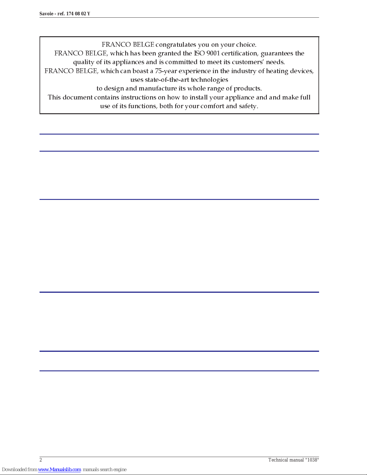
1.5.Operating principle
Heatis mainlydiffusedby radiation, through thewindow
and body of the appliance. The speed control is
obtained by control the oil flow into the burner.
The stove is fitted with a vaporizing burner (fig. 3).
Furnace oil is fed to the burner floor where is it ignited
by means of a firestarter (or with an optional electrical
igniter). The heat produced by this flame brings the
burner temperatureto the required level to vaporize the
oil. Oil will only burn as a vapour not a liquid.
Combustion air enters the burner through the air holes
(# 1, fig. 3). In the center of the burner is the catalyser
(# 2), which aids the the good combustion.
On the feed-line there is a de-scaling lever (# 5). The
de-scaling lever can be operated to keep the inlet pipe
clear of carbon buildup.
The stove float regulator (fig.4) contains a filter(# G)to
trap impurities. A safety lever controls oil flow (# B). A
float in the chamber raises the oil level available to the
burner.
Oil can only enter the float chamber when the safety
lever is depressed.
The carburetor is alsocontrolled by a control knob (# 2,
fig. 14, p. 8) which turns from “off" to ”high setting".
A draftregulator (# 1, fig. 9, p. 6) ensures a constantair
intake to the burner regardless of external factors.
2.Installation instructions
2.1.Warning to the user
An inc orrectly installed heating appliance can
cause serious accidents (chimney fires, burning of
plastic insulation materials, in partition walls, etc.).
The installation must be carried out according to local
building regulations.
The manufacturers responsibility shall be limited to the
supply of the equipment.
2.2.Position of the unit
Ventilation :
For s atisfac tory operation with a na tu ral draught,
check that sufficient air for combustion is available in
the room.
In houses equipped with mechanical ventilation, an
outside air intake must be installed for the chimney.
Chimney position :
For new chimney installations, select a central position
within the building, to provide a good heat distribution
around the building.
Position the unit to comply with the minimum
clearances to combustible material (fig. 1, p. 3).
2.3. Chimney
•The flue must be in good condition and must provide
sufficient draught. (refer to technical details p. 3).
•The flue must be suitable for the installation of fuel
burning appliances and comply with Current Building
Regulations.
•The flu e must be clean. It should be swept to remove
soot and dislodge tar deposits.
•Thefluemustbe well insulate d, water and air tight. A
chimney with a cold internal surface can prevent a
good chimney draught and condensation will occur.
•The flue must be watertight.
•The chimney must have a constant cross section.
1
3
2
2b
2c
4
5
2a
A
F
B
E
C
D
G
Figure 3 - Burner
1 - Air holes
2 - Catalyser
2a - Upper ring
2b - Catalyser top
2c - Catalyser body
3 - Burner pot
4 - Automatic ignition
(optional)
5 - De-scaling lever
Figure 4 - Float regulator
A - Control knob
B - Safety lever.
C - Main float
D - Safety float
E - Oil level regulator
F - Thermostat control
G - Filter
Installation instructionsSavoie - ref. 174 08 02 Y
4 Technical manual "1038"
•The flue must not be shared with any other appliance.
•The chimney m ust be at l eas t 4.5 m (15 ft high).
•If the chimney has any downdraught tendency, due to
its position in relation to nearby obstacles, an
anti-downdraught cowl must be installed on the
chimney or the chimney height must be increased.
•If the chimney draught is excessive or irregular, a
draught stabili zer (barometric damper) must be
installed to the connector pipe.
2.4.Mounting the levelling feet
Figure 5, # 4
Fit the 4 screws and caps supplied on the burner into
each leg of the stove.
2.5. Smoke exit
Figure 5 and 6
The rear exchanger is reversible (2 screws) so that the
smoke exit can be done at rear or on the top
2.6.Chimney connector
•The appliance must be as c lose as possible to the
chimney.
•The connector pipe must be approved for installation
with combustion products (either 24 ga. Black painted
or blued steel or 316 grade 20 ga. Stainless steel or
1 mm vitreous enamelled steel).
•Pipe diameter must not be less than the appliance
spigot diameter.
•The join between the connection pipe and the
stovepipe, and the flue, must be leak tight.
•The connection pipe and any draught stabiliser must
have access for cleaning.
2.7.Levelling
It is essential to ensure that the appliance sits level on
the floor.
- Use a spirit level across the burner pot to check the
level (fig. 7).
3
1
6
4
4
2
5
Figure 5 - Description
1 - Flue collar
2 - Blanking plate
3 - Draught regulator
4 - Control screws for
appliance leveling
5 - Flue baffle
6 - Burner
Figure 6 - Rear flue outlet
1 - Flue collar 2 - Blanking plate
2
1
Figure 7 - Burner level check
Installation ins tructionsSavoie - ref. 174 08 02 Y
Technical manual "1038" 5
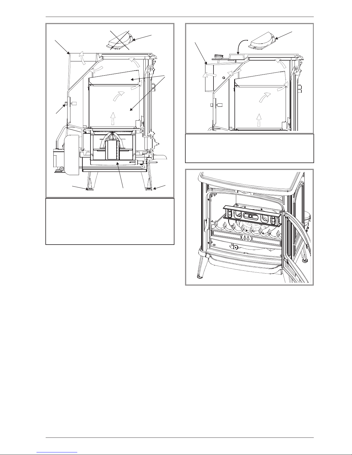
2.8. External / remote tank
Figure 8
•A barometric fuel tankshouldnot be positionnedwhere
it will be in the direct rays of the sun or adjacent to a
source of intense heat.
•If the tank is more than 8 ft (2,5 m) higher than the
stove a pressure reducer must be installed on the oil
line (max. working pressure : 300 mbar).
•If the tank is lower than the stove a lift pump will have
to be utilized.
•A clearance of6 “ (15cm) must bemaintainedbetween
the external/remote tank and the stove.
2.9.Pre-utilization check
- Check that the glasses are not damaged.
- Check that the door closes correctly.
- Check that all removable parts (baffle, catalyser, ring,
etc.) are correctly installed.
- Check that the seals of the smoke-line are in good
condition.
- Ch eck that the seals of the feed-line are in good
condition.
- Light the appliance by referring to the operating
instructions.
2.10. Oil flow adj ust ment
The floatregulator has been adjustedat thefactory and
should not need further adjustment.
The eventu al re-fit must be realized by a qualified
engineer.
If the burner does not work correctly, check possible
causes before readjusting the settings :
- Chimney draught
- Fresh air inlet
- Oil supply.
Minimum speed (# 3, fig. 9) :
- Set the regulating knob on minimum speed (# 3) and
let the burner run for a few minutes. The flame must
completely cover the bottom of the burner and the
catalyser body must be glowing red hot.
- If the flame is too small, the stove will soot up
quickly ; increase the flame by turning the setting
screw (# 3) clockwise.
- If the flame is toohigh, reducethe flame by turning the
setting screw (# 3) counter clockwise.
Maximum speed (# 2, fig. 9) :
- Set the regulating knob on maximum speed (# 2) and
let the burnerrun for afew minutes. Theflamemust be
shaped like a cone and reach the upper part of the
door.
- If theflameis toolow,increase theflameby turning the
setting screw (# 2) counter clockwise.
- If theflame is toohigh,reduce theflame[by turning the
setting screw (# 2) clockwise.
Figure 8 - Gravity oil supply
Pumped oil supply
1 -Max.2,5m
2 -Min.0,25m
3 - Tank
4 -Filter
5 - Suction pomp with
reserve and filter
6 - Pipe 3/8 in. O.D.
5
1
2
6
3
1
3
6
4
2
123
4
5
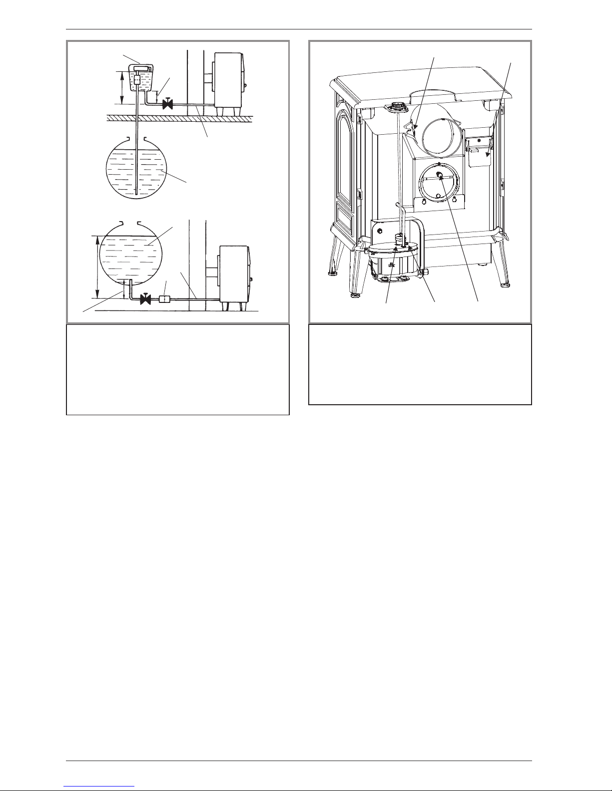
Figure 9 - Adjustment devices
1 - Adjustment of the
draught regulator
2 - Adjustment screw for
high setting
3 - Adjustment screw for
low setting
4 - Safety pressure door
5 - Draught control
Installation instructionsSavoie - ref. 174 08 02 Y
6 Technical manual "1038"
Please note - Very important : The adjustments of the
float regulator are very sensitive. The high and the low
setting screws must never be turned more thana 1/4 of
a turn at a time in any direction from their initial setting.
When making any adjustments, allow 3 to 5 minutes
between adjustments to allow burner to stabilize to
previous adjustment before proceeding, if necessary.
2.11. Chimney draft required
The reading of the draught must be done once the unit
is hot (minimum 30 minutes of use).
Refer to the specifications (page 3) fo r min im um
draught requirement. The eventual re-fit must be
realized by a qualified engineer.
The adjustment of the draught will be made with the
barometricdamper located at the backof the stove(# 1,
fig. 9)
2.12. Maintenance of the Chimney
Chimney condition should be checkedat leastonce per
year.
If the appliance is regularly used, the chimney should
be swept several times per year, together with the
stovepipeconnection section (andalso the fluebaffles).
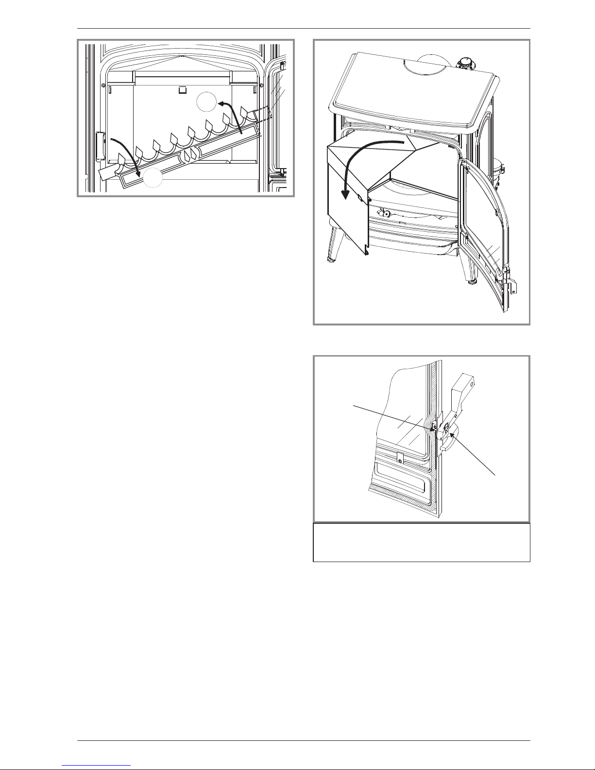
- First remove the flue baffle (fig. 11)
- The barometric damper (draught regulator # 1, fig. 9)
should be checked at least once per year.
2.13. Door closing pressure
Figure 12
The closing latch rotates around a pressure screw
positioned cam.
- Remove gently the ceramics rope,
- Loosen pressure screw (# 1),
- Turn cam (# 2) to desired position,
- Tighten pressure screw (# 1).
1
2
1
2
Figure 10 - Removing the front grate
Figure 11 - Removing the flue baffle
Figure 12 - Door closing pressure
1 - Pressure screw
2 -Cam
Installation ins tructionsSavoie - ref. 174 08 02 Y
Technical manual "1038" 7
2.14. Removing the burner
To remove the burner :Remove the lower paneland the
magnet support, disconnect the feed line from the
de-scaler nut, unscrew the 4 burner fixing nuts.
3.Instructions for user
Franco Belge will not be responsible for damages on
parts of the appliance due to the useof prohibited fuel
or d ue to an alteration of the appliance or its
installation.
3.1.Fuel
Your stove is fitted with a specific float regulator for a
specific oil.
The fuel oil must be free from any dirt and water,which
could disturb the stove in operation.
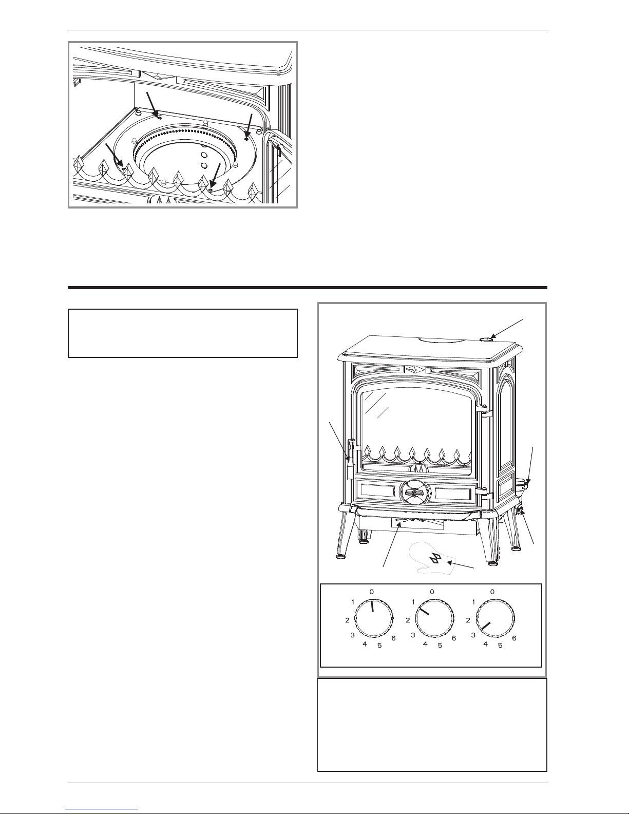
3.2.Lighting procedure
Figure 14
Don’t light the appliance when it is hot. Wait until the
burner is completely cool before repeating the lighting
procedure.
- Be sure the control knob (# 2A) is to “0".
- Turn on oil supply,
- Push down gently on the safety lever (# 4). This will
allow the oil to flow into the float regulator.
- Open the front door, and remove the catalyser from
burner(#2,3,4,fig.3,p.4).Makesuretheinsideof
the pot is clean thoroughly, and there is no oil
accumulation.
- Place 2 tablespoons of methylated spirit or gelled
alcohol in the bottom of the pot.
- Light thestartergel or methylatedspiritwith a fireplace
match or long butane lighter.
- Place the catalyser back into the burner, being sure it
is centered in the burner. Shut the main door.
- Allow the burner to heat approximately 30 to 45 sec.
Turn dial to “1" position (# 2B).
- Allow 10 to 15 minutes for oil fire and draught to
stabilize. The catalyser (or the ring) should glow red
before adjusting the control knob to a higher setting
(# 2C).
6
4
2
5
3
Figure 14 - Operating devices
1 - Gant de protection
2 - Regulation knob.
2A - Shutting down
2B - Lighting procedure
2C - Normal speed
3 - Opening and closing
of the window
4 - Safety lever.
5 - Access to regulator’s
filter
6 - De-scaling lever.
2A
2B
2C
1
Figure 13 - Removing the burner
Instructions for userSavoie - ref. 174 08 02 Y
8 Technical manual "1038"

3.3.Operating procedure
•Allow 10 to 15 minutes after lighting to adjust the
control knob to a higher setting, usually (# 2C) setting.
•When increasing the heat output, move the control
knob only 1 number at a time, allowing 5 minutes
between moves for the flame to re-adjust to new
setting.
•If the burner stops during operating, immediately turn
offthe control knobposition“0" (#2A)and waituntilthe
burner is completely cool before repeating the lighting
procedure.
3.4.Shutting down
Figure 14
- Set dial to the (# 2A) position.
- Raise the safety lever of the regulator (# 4).
- Allow the flame to burn out completely before opening
the door (# 3).
3.5.Recommendations
•The adjustment of the stove has been made at the
factory and checked byyour installer.In caseoftrouble
shooting, do the usual maintenance operations. If
problem persists call your installer.
•This room heater is a high heat producing appliance
and may cause severe burns if touched on the glass
front door, or on top directly over the burner - keep
children away.
•CAUTION : Never light th e burner if there is any
amount of oil in pot. Clean out oil before lighting.
•Too much oil in pot may cause a racing : a very high
flame generating vibrations.
In case of racing :
- Turn off oil supply.
- Set dial to the “0" position (# 2A, fig. 14, p. 8).
- Wait until the burner is completely cool before
repeating the lighting procedure.
•Do notoverfire.If the unitor chimney connector starts
to glow you are overfiring.
3.6.Maintenance of the stove
•Everyweek:operate the de-scaling lever (# 6, fig. 14,
p. 8). Pull the rod, then push the rod in rotating 360
degrees two or three times.
(CAUTION : The rod is HOT).
•Every3or4months: Clean the burner completely.
- Remove and brush off the parts of the catalyser, using
a soft bristle brush.
- Loosen any carbon soot from the burner with a putty
knife, and vacuum clean. Ensure that the small air
holes are free of carbon.
- When replacingtheburner,tightenthe nuts evenly and
connect the pipe so as to be airtight.
•At least once a year / Endof heatingseason : Clean
or replace the oil filters of the oil supply line (# 5,
fig. 14, p. 8).
To clean the filter of the float regulator :
- Set the regulation knob in closed position “0" (# 2A,
fig. 14, p. 8).
- Turn o ff the tankvalveor the valveof the oilsupplyline.
- Raise the safety lever of the float regulator (# 4,
fig. 14, p. 8).
- Place a small container (or a small rag) under the
regulator filter opening in order to collect the oil
contained in the regulator.
- Remove the filter cover plate located under the
regulator (# 5, fig. 14, p. 8) with a screwdriver,
- Remove the tubular filter from the regulator. Clean it
with oil using a soft brush, never a wire-brush.
- Replace the filter in the regulator, install the cover
plate and secure with the screw.
¤ Use a soft clean cloth to wipethe frontglass whenthe
unit is running at a low burning rate.
¤ When the main door is opened for cleaning, the flame
will be disturb,and turnto a yellowflame. Clean quickly,
but gently. Close the door, the flame will return to a
normal burning position.
¤ Clean all the enamelledpanels of thestove with a dry
or slightly damp soft cloth.
DO NOT CLEAN GLASS WHEN HOT.
Instructions for userSavoie - ref. 174 08 02 Y
Technical manual "1038" 9
 Loading...