

FRANCO BELGE SAVOIE 134 08 03 Technical Manual
Description of the appliance
Installation instructions
Operating instructions
Spare parts
Warranty certificate
Document n° 957-16 ~ 15/12/2006
STAUB FONDERIE
SARL with the capital of 6 359 540
Head Office Address
2, rue Saint Gilles
68230 TURCKHEIM
RCS Colmar
SIREN 444 881 953
Address
Administration and manufacturing
BP 73
59660 MERVILLE (FRANCE)
Telephone : 00 333 28 43 43 00
Fax : 00 333 28 43 43 99
Subject to modifications.
SAVOIE
Wood stove
EN 13240
Model : 134 08 03
Output:8kW
Technical manual
to be saved
by the user
for future reference
NLFR IT PT EN

2 Technical manual “957”
“SAVOIE” - model : 134 08 03
CONTENTS
Product information .....................................p.3
Package ..................p.3
Optional ..................p.3
General characteristics. . ........p.3
Description . . . . . . . . . . . . . . . . p. 3
Principle of operation. . . . . . . . . . . p. 3
Installation instructions...................................p.4
Warning to the user . ..........p.4
Location of the unit ............p.4
Chimney..................p.5
Assembly of flue spigot .........p.5
Chimney connector ............p.6
Mounting the tray . . . . . . . . . . . . . p. 6
Door closing pressure . . . . . . . . . . p. 6
Pre-utilisation check . . . . . . . . . . . p. 7
Maintenance of the Chimney . . . . . . p. 7
Instructions for user.....................................p.8
Fuel . . . .................p.8
Lighting ..................p.9
Operating procedure . ..........p.9
Loading the fuel .............p.9
De-ashing .................p.9
Maintenance of the stove body . . . . . p. 9
Maintenance of the Chimney . . . . . . p. 9
Recommendations . . . . . . . . . . . p. 10
Trouble Shooting . . . . . . . . . . . . p. 10
Spare parts .........................................p.12
FRANCO BELGE congratulates you on your choice.
FRANCO BELGE, guarantees the quality of its appliances and is committed to meet its
customers’ needs.
FRANCO BELGE, which can boast a 80-year experience in the industry of heating devices, uses
state-of-the-art technologies
to design and manufacture its whole range of products.
This document contains instructions on how to install your appliance and make full use of its
functions, both for your comfort and safety.
This appliance is meant to burn wood safely
Warning
An incorrectly installed wood stove can cause serious accidents.
We recommend that you engage the services of a professional engineer for its installation
and the regular maintenance requirements
1. Product information
1.1. Package
•
1 package : Stove complete.
1.2. Optional
•
Set of 4 short legs (only 134 08 03 Y)
1.3. General characteristics
Reference ................ 1340803
Maximum output ...........kW 8
Chimney draught required ......Pa 12
Usable firebox dimensions
- width ................mm 450
- depth ................mm 240
- height ................mm 365
Log dimensions
- Lenght maxi .............cm 40
Ash pan capacity ..........litres 3
Net weight ...............kg 100
Volume heated ............m
3
300
Autonomy ................h 10
Flue mass flow on the rear
- Efficiency classification .......% 74,1
- Co (13% O
2
).............% 0,29
- Mean flue gas temperature .....°C 305
- Flue mass flow ...........g/s 8,48
Flue mass flow on the top
- Efficiency ...............% 73,6
- Co (13% O
2
).............% 0,28
- Mean flue gas temperature .....°C 301
- Flue mass flow ...........g/s 8,72
Note : The performances indicated result from tests
carried out in accordance with standard EN13240 with
logs of Ø 12 of 40 cm and a draught of 12 Pa.
1.4. Description
•
Wood stove in conformity with EN 13240
•
Continuous-burning heating appliance.
•
Wood burnt on grate
•
Enclosed combustion chamber with refractory brick
walls.
• Removable appliance, to be installed near a wall.
•
Detachable flue spigot for rear or top chimney
connection.
•
Detachable top for easy handling and cleaning (rear
smoke exit only).
•
Loading door with a side opening (to the right of the
appliance)
•
Adjustable air controls for controlling the burning rate.
•
Spin wheel for lighting.
•
Large ash-pan.
•
Long lasting burning cycle :
When the appliance is loaded
with à 4,8 kg (see page 8, § 3.1.)
of dry rate (primary and
secondary air inlet closed) with
a 6 Pa draught, it runs for 11
hours.
1.5. Principle of
operation
The appliance is designed for
operation with the door closed.
Heat is mainly diffused by
radiation, through the window
and body of the appliance.
Combustion occurs on the grate,
with draught entry through the
top of the combustion chamber
when using wood and under the
grate when using coal.
Technical manual “957” 3
“SAVOIE” - model : 134 08 03 Product information
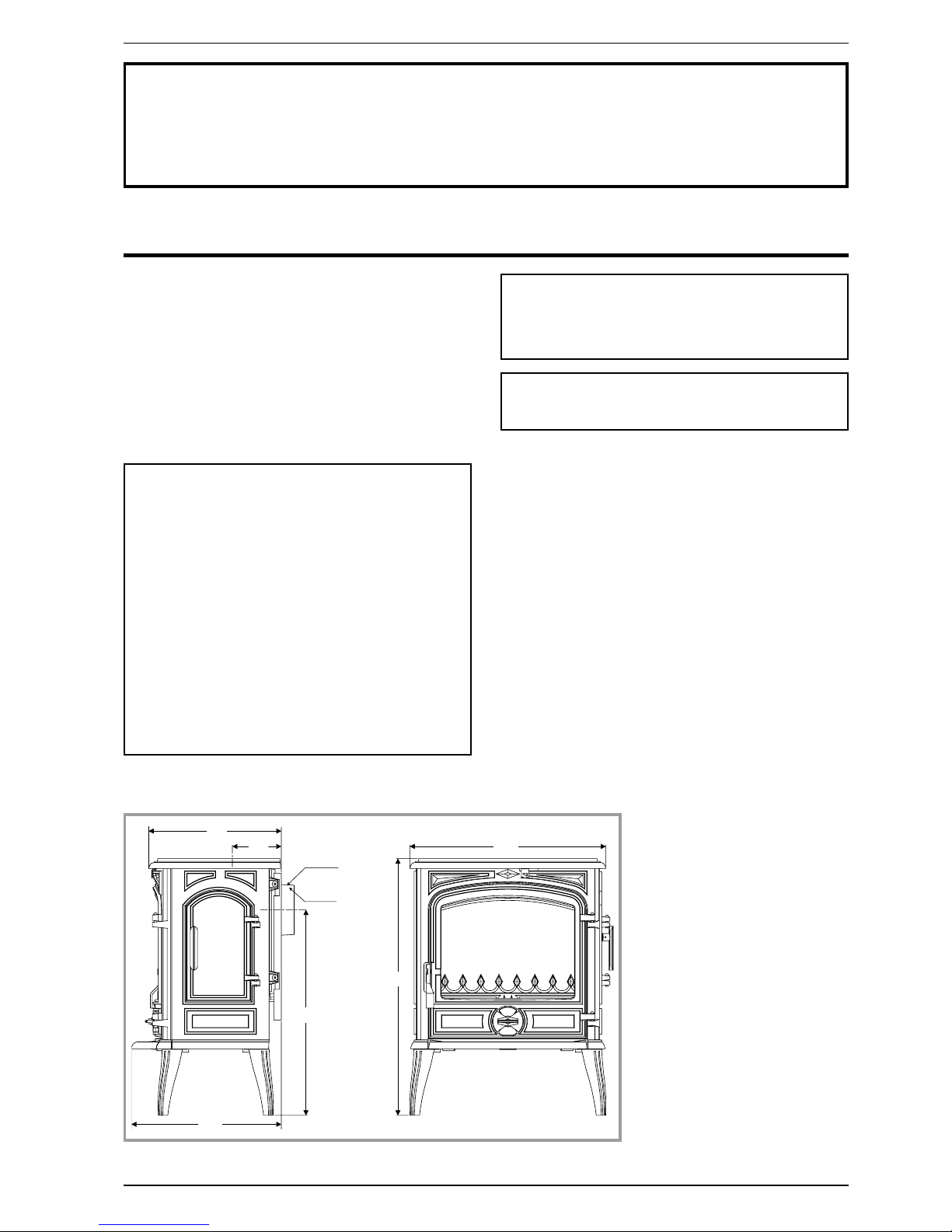
1 3 4
5 6 0
4 0 9
7 0 0
5 3 5
Ø 1 2 5
Ø 1 3 9
3 6 0
Figure 1 - Dimensions in mm
2. Installation instructions
2.1. Warning to the user
All the local and national regulations, and in
particular those relating to national and European
standards, must be observed when installing the
appliance.
An incorrectly installed heating appliance can
cause serious accidents (chimney fires, burning of
plastic insulation materials, in partition walls, etc.).
The insulation of both the appliance and the
exhaust gas pipe has to be reinforced and done
according to the Standards and the Building
Regulations for safety reasons.
Failure to respect the mounting instructions leads to
engage the responsibility of the one doing the
installation.
The manufacturer’s responsibility shall be limited to the
supply of the equipment.
2.2. Location of the unit
Ventilation : For satisfactory appliance operation with a
natural draught, check that sufficient air for combustion
is available in the room.
Position of the unit : For new installations, select a
central position within the house, to provide a good heat
distribution around the building.
The heat distribution towards the other rooms will be
made through the communicating doors.
These rooms must be in negative pressure or must
include ventilation gratings.
Floor and walls : Make sure they are not combustible
or covered with combustible material (as per the
Building regulations).
Otherwise it must necessary to install a
non-combustible protection.
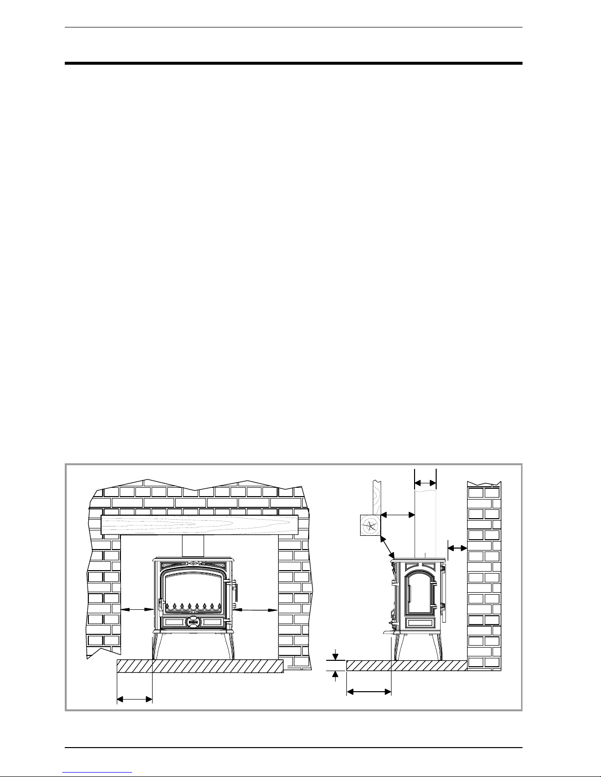
There must be a clearance of at least 150 mm at each
side of the appliance and at the back of the appliance
from a non-combustible wall.
This distance must be extended to a minimum
clearance of 350 mm from any combustible materials.
This measurement may be reduced to a minimum gap
of 50 mm when the non-combustible wall is at least
200 mm thick.
When using a single wall flue pipe, there must be a
clearance (A) of at least three times its diameter (B)
from any combustible materials.
If the appliance has to be located in an opening, this
distance must be extended to a minimum clearance (A)
of 375 mm from the pipe or the stove body to any
combustible materials.
Hearth : The appliance must stand on a fireproof
hearth.
It is possible to provide a hearth made of non
combusible board/sheet material or tiles at least 12 mm
thick.
Constructional hearths should be constructed of solid
non combustible material at least 125 mm thick
(including the thickness of any non combustible floor
under the hearth).
The hearth must protrude at least 225 mm in front of the
stove and 150 mm each side.
If the hearth is constructed on timber, there must be a
clearance of at least 250 mm from the timber to the top
surface of the hearth.
See section J of the Building regulations.
4 Technical manual“957”
“SAVOIE” - model : 134 08 03 Installation instructions
4 0 0
1 5 0
1 5 0
3 0 0
1 5 0
B
A
A
C
Figure 2 - Minimum clearances
2.3. Chimney
The chimney must comply with Current Building
Regulations. If in doubt, consult your Dealer or local
Building Inspector.
Existing flue :
-
The flue must be in good condition and must provide
sufficient draught (refer to technical details p. 3).
-
The flue must be suitable for the installation of fuel
burning appliances, otherwise it must necessary to
install a tubing.
-
The flue must be clean. It should be swept to remove
soot and dislodge tar deposits.
-
The flue must be well insulated. If the flue inner wall
surfaces are cold, a good thermal draw is impossible
causing condensation problems (tar formation etc) to
occur.
-
The flue must be watertight.
-
The flue must not be shared with other appliances.
-
The chimney must have a constant cross section.
-
When the cross-section of the chimney is too large, it
has difficulties in obtaining a good draught.
-
The recommended minimum flue height is 5 metres.
-
In case of a flat roof or when the roof gradient is lower
than 15°, the stack must be 1,2 m (4 feet) high at least.
-
If the chimney has any down draught tendency, due to
its position in relation to nearby obstacles, then an
anti-down draught cowl must be installed on the
chimney or the chimney height must be increased.
-
If the chimney draught is excessive or irregular, a
draught stabiliser must be installed. It must be visible
and accessible.
Chimney to be built / new flue : The chimney must
comply with Current Building Regulations. If in doubt,
consult your Dealer or local Building Inspector.
-
The appliance must not support the weight of the flue.
-
Consult a chimney specialist for advice on suitable
flue systems for solid fuel appliances.
-
It must be distant from any combustible material
(walls, cross members)
-
It must permit an easy sweeping.
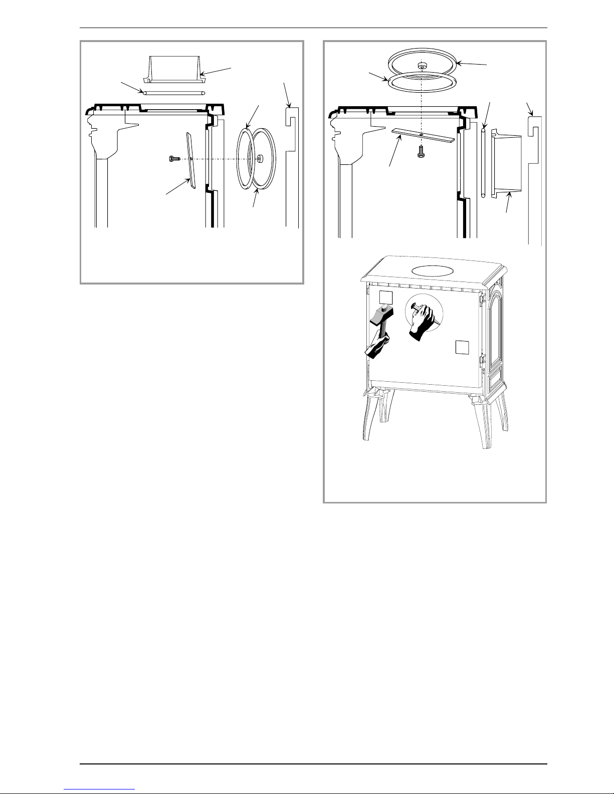
2.4. Assembly of flue spigot
The stove is supplied with a connection flue spigot with
an inner diameter of 125 mm and an outer diameter of
139 mm.
2.4.1. Smoke exit on the top (figure 3)
-
Fit the sealing rope 2 in the groove on the top and fix
the flue collar 1 with 3 bolts and washers supplied.
2.4.2. Smoke exit at rear (figure 4)
-
Remove the rear heat shield and remove the
preformed hole plate.
Technical manual “957” 5
“SAVOIE” - model : 134 08 03 Installation instructions
1
2
3
4
2
5
Figure 3 - Smoke exit on the top
1 - Flue collar
2 - Sealing rope
3 - Blanking plate
4 - Clamp
5 - Back panel
1
2
3
4
2
5
Figure 4 - Smoke exit at rear
1 - Flue collar
2 - Sealing rope
3 - Blanking plate
4 - Clamp
5 - Back panel
 Loading...