

FRANCO BELGE Parisienne 124 03 01, Parisienne 124 05 01 Technical Manual
Document n° 286-20 ~ 09/07/2007
STAUB FONDERIE
SARL with the capital of 6 359 540 !
Head Office Address
2, rue Saint Gilles
68230 TURCKHEIM
RCS Colmar
SIREN 444 881 953
Address
Administration and manufacturing
BP 73
59660 MERVILLE (FRANCE)
Telephone : 00 333 28 43 43 00
Fax : 00 333 28 43 43 99
Subject to modifications.
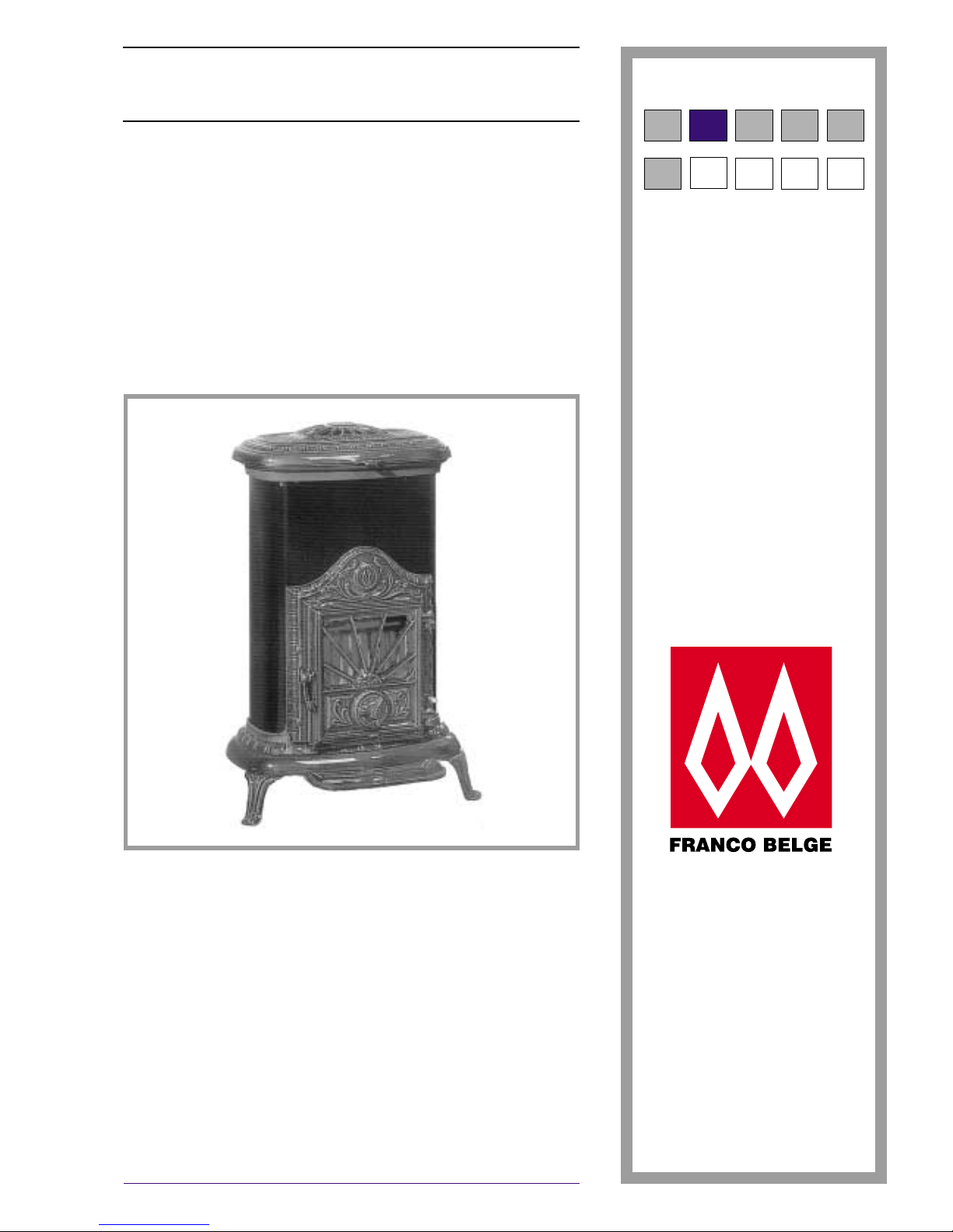
La Parisienne
Multifuel stove
124 03 01 - 124 05 01
How to install, use and maintain your stove.
Norme DIN EN 13240 : 2005-10
Description of the appliance
Installation instructions
Operating instructions
Spare parts
Warranty certificate
FR EN NL ES PT
PL
PL
PL PL PL
Technical manual
to be saved
by the user
for future reference

2 Technical manual “286”
The Parisienne - ref. 124 03 01 - 124 05 01
CONTENTS
Description of the unit....................................p.3
Package .................p.3
Specifications . . . . . . ........p.3
Regulations. . . . . . . . . . ......p.3
Installation instructions ...................................p.4
Warning to the user ...........p.4
Location of the unit ...........p.4
Chimney .................p.5
Hearth . .................p.5
Connections to flues ...........p.6
Mounting the tray . . . .........p.6
Door closing pressure . . . . . . . . . . p. 6
Pre-utilisation check . . . . . . . . . . . p. 6
Soot Doors . . . . . . . . . . ......p.6
Commissioning. . . . . . . . . . . . . . p. 6
Chimney maintenance and sweeping . p. 6
Operating instructions ...................................p.7
Fuel ....................p.7
Lighting your stove. . . .........p.8
Air inlets .................p.8
Maintenance . ..............p.8
Chimney maintenance and sweeping . p. 9
Recommendations . . . . . . . . . . . . p. 9
Fire-bricks . . . . . . . . . . ......p.9
Trouble Shooting. . . ..........p.9
Spare parts .........................................p.10
Ref. 124 03/05 01 L, J, Y .......p.10 ref. 124 03/05 01 C. . . . . . . . . . . p. 12
FRANCO BELGE congratulates you on your choice.
FRANCO BELGE, guarantees the quality of its appliances and is committed to meet its
customers’ needs.
FRANCO BELGE, which can boast a 80-year experience in the industry of heating devices, uses
state-of-the-art technologies
to design and manufacture its whole range of products.
This document contains instructions on how to install your appliance and make full use of its
functions, both for your comfort and safety.
Warning to the user
A wood stove should only be installed by competent personnel, in the strict application of
normal practices and all safety precautions.
An incorrectly installed wood stove can cause serious accidents (chimney fires, burning of
plastic insulation materials, in partition walls, etc.).
The manufacturer’s responsibility shall be limited to the supply of the equipment.
1. Description of the unit
1.1. Package
•
1 package : Stove complete.
1.2.
Specifications
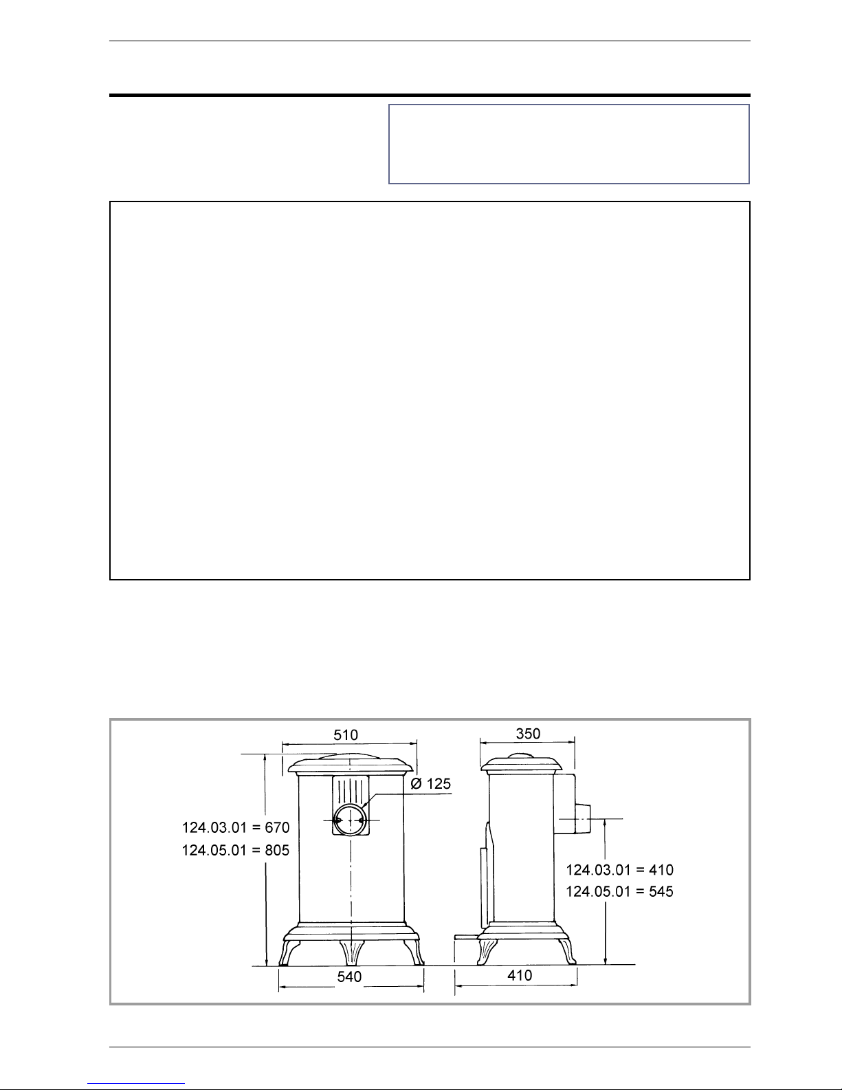
Reference ..................................1240301 ......1240501
Dimensions of the firebox
Width ...........................mm.........340..........340
Depth ...........................mm.........180..........180
Usable height .......................mm.........250..........315
Logs dimensions
Lenght maxi ........................cm..........25...........30
Ash pan capacity .....................liter .........2,5..........2,5
Weight ...........................kg..........80...........95
Wood burning :
Nominal heat output ...................kW .........5,3 ..........9,3
Chimney draught required ................Pa..........10...........12
Efficiency ..........................%.........75,9..........74,7
Co (13% O
2
)........................%.........0,48..........0,52
Mean flue gas temperature ................°C.........277..........283
Combustible flow.....................kg/h .........1,6 ..........2,8
Roam heating volume capacity ..............m
3
.........162..........349
Sunbrite (Small) - Anthracite (Medium) :
Nominal heat output ...................kW .........3,1 ..........5,1
Chimney draught required ................Pa..........10...........10
Efficiency ..........................%.........51,9..........69,8
Co (13% O
2
)........................%.........0,48..........0,48
Mean flue gas temperature ................°C.........288..........164
Combustible flow.....................kg/h .........0,7 ..........0,9
Roam heating volume capacity ..............m
3
..........80 ..........154
1.3. Regulations
Important : Before commencing the installation of your
new Franco Belge appliance, it is recommended that
the instructions are read and understood.
•
Health and Safety at Work Act 1974 : The installation
should comply with the Health and Safety at Work Act
1974 and particular reference to the following.
•
Handling : Adequate facilities should be provided for
handling the appliance.
•
Glass : On Franco Belge models incorporating glass
doors, extra care should be taken to avoid breakage.
•
Fire cement : Care should be taken to avoid fire
cement contacting the skin. The material is caustic and
the event of contact being made, wash off immediately
with clean water.
Technical manual “286” 3
The Parisienne - ref. 124 03 01 - 124 05 01
Figure 1 - Dimensions in mm
Description of the unit
A draft regulator must be installed and set in such a way as
to obtain maximum depression of 15 Pa. Settings must be
made after hot measurement (machine operating for 30
minutes minimum). If these instructions are not followed
all guarantees will be invalid.
2. Installation instructions
The Parisienne comes bolted to a wooden pallet with a
box over the top.
2.1. Warning to the user
All the local and national regulations, and in
particular those relating to national and European
standards, must be observed when installing the
appliance.
An incorrectly installed heating appliance can cause
serious accidents (chimney fires, burning of plastic
insulation materials, in partition walls, etc.).
The installation must comply with Current Building
Regulations. If in doubt, consult your Dealer or local
Building Inspector.
It is the installer’s responsability to conform to local
building standards and requirements with regard to
installation.
The manufacturer’s responsibility shall be limited to the
supply of the equipment.
2.2. Location of the unit
Ventilation :
For satisfactory appliance operation with a natural
draught, check that sufficient air for combustion is
available in the room. In this case, the residence is
under slight low pressure and a non-sealable external
air intake must be installed in addition to the chimney
itself, at least 50 cm² in section.
Chimney position :
For new chimney installations, select a central position
within the building, to provide a good heat distribution
around the building. These rooms must be at low
pressure or fitted with non-adjustable air registers,
placed so that they cannot be obstructed, to encourage
circulation of the hot air.
Hearth :
The hearth must be suitable for use with solid fuel
burning appliances and must comply with Current
Building Regulations. If in doubt, consult your Dealer or
local Building Inspector.
Rear wall and ceiling :
The appliance must not be positioned close to
combustible materials, wall & ceiling surfaces etc.,
Consult your Dealer or local Building Inspector if in
doubt.
Make sure that the floor can support the weight of the
appliance its surroundings and the hood ; In the
contrary the floor needs to be reinforced with a concrete
screed to distribute this load.
Provide adequate insulation if the floor is combustible.
The protections for the floor, it is obligatorily
non-combustible.
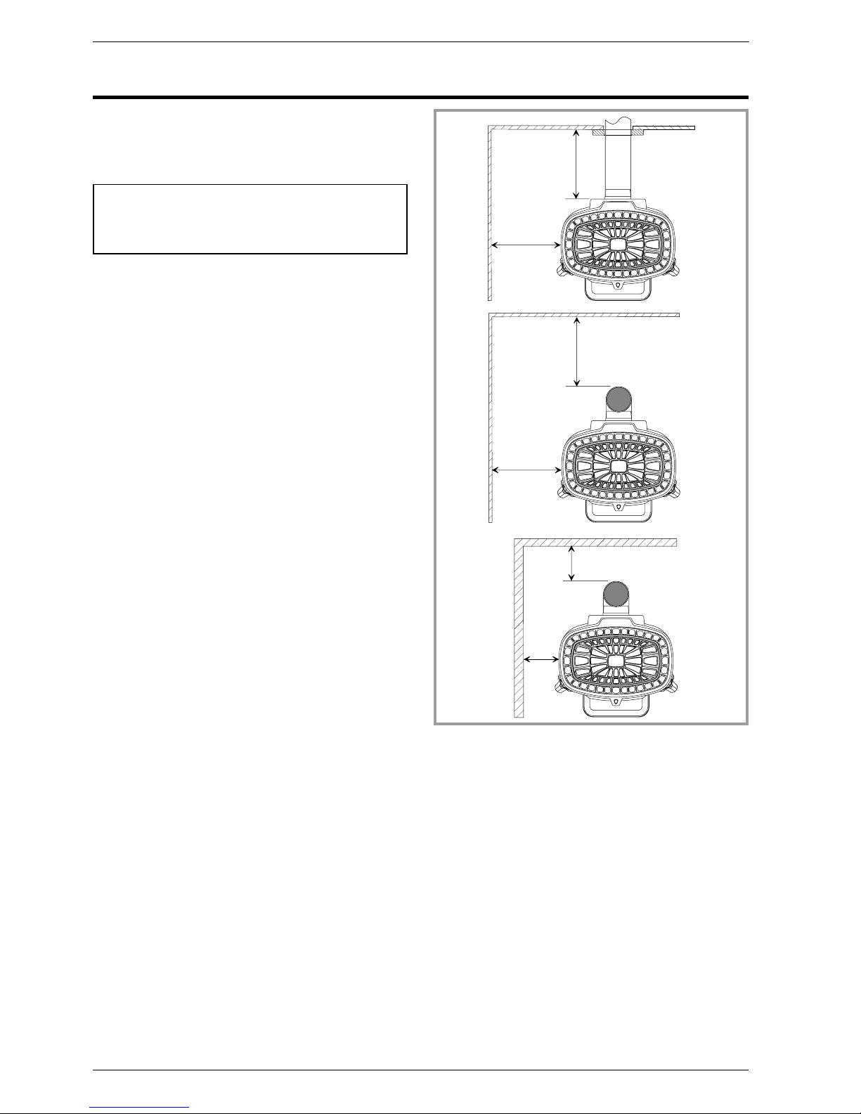
Position the unit to comply with the minimum
clearances to combustible material (rep. A and B,
fig. 2) and the non-combustible material (rep. C,
fig. 2). Do not place any object or combustible
material, curtains, hangings,etc inside the interior
of the appliance.
4 Technical manual “286”
The Parisienne - ref. 124 03 01 - 124 05 01
Installation instructions
6 0 0 m m
6 0 0 m m
6 0 0 m m
6 0 0 m m
1 5 0 m m
1 5 0
m m
A
B
C
Figure 2 - Minimum clearances

2.3. Chimney
The chimney must comply with Current Building
Regulations. If in doubt, consult your Dealer or local
Building Inspector.
-
Chimney to be built / New flue :
The chimney must comply with Current Building
Regulations. If in doubt, consult your Dealer or local
Building Inspector.
-
The flue must be in good condition and must provide
sufficient draught (refer to technical details p. 3 ).
-
The flue must be clean. It should be swept to remove
soot and dislodge tar deposits.
-
The flue must be well insulated. If the flue inner wall
surfaces are cold, a good thermal draw is impossible
causing condensation problems (tar formation etc.) to
occur.
-
The flue must be watertight.
-
The chimney must have a constant cross section.
-
The flue must not be shared with other appliances.
-
The chimney must be at least 4.5 m (15 ft high).
-
In case of a flat roof or when the roof gradient is lower
than 15°, the stack must be 1,2 m (4 feet) high at least.
-
The capping must not restrain the draught.
-
If the chimney draught is excessive or irregular, a
draught stabilizer (barometric damper) must be
installed to the connector pipe it must be visible and
accessible.
Flue non-existent :
-
The chimney must comply with Current Building
Regulations. If in doubt, consult your Dealer or local
Building Inspector.
-
The flue must not be supported by the stove.
-
Consult a chimney specialist for advice on suitable
flue systems for solid fuel appliances.
-
It must be distant from any combustible material
(walls, cross members)
-
It must permit an easy sweeping.
2.4. Hearth
The stove must stand on a fireproof hearth and must be
situated at least 300 mm (12 inches) from any
combustible material.
The positioning of the stove and the size of the hearth
are governed by building regulations for Class 1
appliances.
These building regulations state that the hearth must
extend in front of the stove by at least 300 mm
(12 inches) and to the sides of the stove by at least 150
mm (6 inches) If in doubt as to the positioning of the
stove expert advice should be sought either from the
supplier or the local building inspector.
Technical manual “286” 5
The Parisienne - ref. 124 03 01 - 124 05 01
7
1
4
5
2
3
6
1
7
Figure 3 - Connections to flue
Installation instructions
X - Forbidden
1 - Flue duct
2 - Stainless funnel-shaped register
3 - Encasing of the flue connector : 40 mm
4 - Funnel-shaped fire cement
5 - Flange
6 - The flange does not extend beyond the encasing
7 - Soot door
 Loading...