

FRANCO BELGE 134 05 02, Montfort Mk2 EA Technical Manual

Montfort Elegance
Montfort Mk2 EA
Wood burning stove
EN 13240
Model : 134 05 02
Nominal output : 5 kW
Description of the appliance
Installation instructions
Operating instructions
Spare parts
Warranty certicate
Document n°1300-5 - 20/03/2012
Technical manual
to be saved
by the user
for future reference
THIS APPLIANCE CAN BE INSTALLED IN UK SMOKE
CONTROL AREAS ONLY USING WOOD FUEL
Parc d’activités de la Verte Rue
Allée des Prêles
59270 BAILLEUL
Tél. : 03 28 40 32 50
Matériel sujet à modications
sans préavis.
Document non contractuel.
Montfort MK2 EA - 1340502
2 Technical manual "1300"
Package ......................................................p. 3
General characteristics ................................. p. 3
Description .................................................p. 3
Principle of operation ................................... p. 3
Warning to the user .....................................p. 4
The room ....................................................p. 4
Chimney .....................................................p. 5
Mounting the ue collar ............................... p. 5
Top ue outlet ............................................. p. 5
Rear ue outlet ........................................... p. 5
Chimney connector ......................................p. 5
Pre-utilisation check ....................................p. 5
Door closing pressure ...................................p.6
Maintenance of the chimney.........................p. 6
Removing and replacing the ue bafe .........p. 6
Fuel ............................................................p. 8
Instructions for use with wood ..................... p. 9
Instructins for use with solid fuel .................. p. 9
Cleaning .....................................................p. 9
Maintenance of the chimney.........................p. 8
Maintenance of the stove .............................p. 8
Recommendations .......................................p. 9
Trouble shooting ....................................... p. 10
FRANCO BELGE congratulates you on your choice.
FRANCO BELGE, guarantees the quality of its appliances and is committed to meet
its customers’ needs.
FRANCO BELGE, which can boast a 80-year experience in the industry of heating devices,
uses state-of-the-art technologies
to design and manufacture its whole range of products.
This document contains instructions on how to install your appliance and make full use of
its functions, both for your comfort and safety.
CONTENTS
Product information .................................................................................................................... p. 3
Installation instructions ............................................................................................................... p. 4
Instructions for user ....................................................................................................................p. 8
Spare parts ..................................................................................................................................p. 11
Montfort MK2 EA - 1340502
Technical manual "1300" 3
1.1. Package
• 1 package : stove.
1.2. Optional equipment
• Kit air intake
1.3. General characteristics
1.4. Description
Stove, in conformity with EN 13240
• Intermittent-burning heating appliance.
• Detachable ue spigot for rear or top chimney
connection.
• Front loading door tted with large refractory glass
panel.
• Adjustable air controls for controlling the burning
rate.
• Large ash-pan.
• Air wash system
1.5. Principle of operation
The “Montfort MK2” is designed for operation with
closed door. Heat is mainly diffused by radiation,
through the window and body of the appliance.
Combustion occurs on the grate, with air in let through
the top of the combustion chamber.
Reference ........................................ 134 05 02
Nominal heat output ............................. kW 5
Chimney draft required .......................... Pa 12
Hearth dimensions
- width ............................................... mm 335
- depth ............................................... mm 205
- height .............................................. mm 250
Log dimensions
- lenght maxi ........................................cm 20
Ash pan capacity ................................litres 2,2
Flue gas mass ow ............................... g/s 4,50
Net weight ............................................ kg 81
Heated Volume .................................... m3 130
Efciency ...............................................% 78
Co (13% O2) .........................................% 0,14
Mean ue gas temperature .................... °C 296
Dust emission .............................. mg/Nm3 50
The performances indicated result from tests carried out
in accordance with standard EN 13240 with a fuel mass
1,4 kg and a draught of 12 Pa.
1. Product information
This appliance is meant to burn wood safely
WARNING
Incorrectly installed, this appliance can be dangerous and possibly cause serious accidents.
We recommend that you engage the services of a professional engineer for its installation
and the regular maintenance requirements
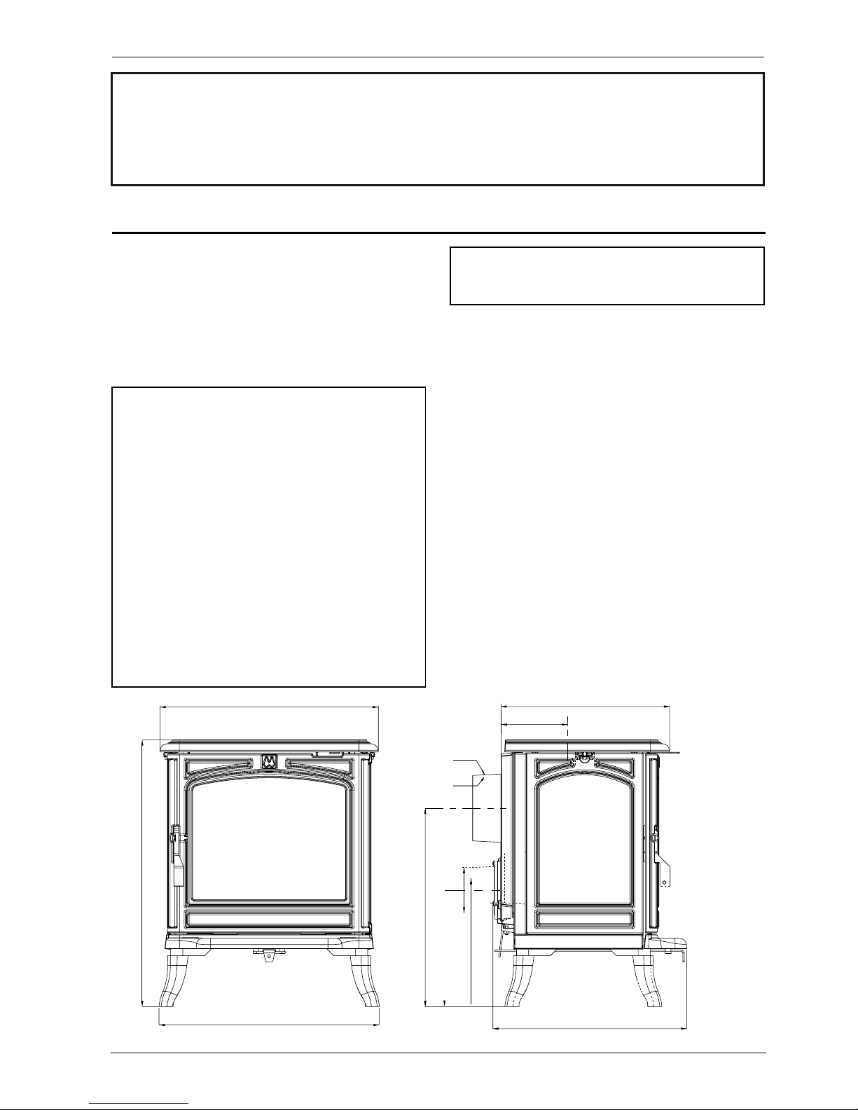
Figure 1 - Dimensions in mm
550
450
454
137
409
Ø 100
400
347
Ø 139
Ø 125
240

Montfort MK2 EA - 1340502
4 Technical manual "1300"
2.1 Warning to the user
All the local and national regulations, and
in particular those relating to national and
European standards, must be observed when
installing the appliance.
An incorrectly installed heating appliance can
cause serious accidents (chimney res, burning of
plastic insulation materials in partition walls, etc.).
The insulation of both the appliance and the exhaust
gas pipe has to be reinforced and done according to
the Standards and the Bui lding Regulations for safety
reasons. The installation must be carried out according
to the standards and the Building Regulations.
It is the installer responsability to ensure that the
manufacturer's intructions are complied with.
2.2. The room
Ventilation
: To ensure that the appliance operates
correctly it is vital that sufcient air is provided for
combustion purposes. Check that sufcient air is
available in the room for combustion. Il a VMC
(controlled mechanical ventilation) is present, the
room pressure will be low and a non-closing external
air intake must be installed in addition to the chimney
itself of a minimum 50 cm2.
Position of the unit
: For new installations, select a
central position within the house, to provide a good
heat distribution around the building.
The heat distribution towards the other rooms will be
made through the communicating doors.
These rooms must be in negative pressure or must
include ventilation gratings.
Floor and walls
:
Make sure that the oor can support the weight of the
appliance, it's ue and any surround. The oor May
need to be re-inforced with e concrete screed to
distribute the weight load. The oor must not be
made of or covered with combustible materials, as
per the Building Regulations. Il combustible material is
present it will be necessary to install a non-combustible
covering.
There must be a clearance of at least 150 mm at each
side of the appliance and at the back of the appliance
from a non-combustible wall.
This distance must be extended to a minimum
clearance of 550 mm from any combustible materials
(gure 2a). This measurement may be reduced to a
minimum gap of 50 mm when the non-combustible
wall is at least 200 mm thick.
When using a single wall ue pipe, there must be a
clearance (A) of at least three times its diameter (B)
from any combustible materials.
Figure 2 a - Clearance
2. Installation instructions
Figure 2 b - Clerances
150
150
150
150
550 mm
525 mm

Montfort MK2 EA - 1340502
Technical manual "1300" 5
If the appliance has to be located in an opening, this
distance must be extended to a minimum clearance
(A) of 550 mm from the pipe or the stove body to any
combustible materials.
Hearth
: The appliance must stand on a reproof
hearth.
It is possible to provide a hearth made of non
combusible board/sheet material or tiles at least 12
mm thick (C).
Constructional hearths should be constructed of
solid non combustible material at least 125 mm thick
(including the thickness of any non combustible oor
under the hearth).
The hearth must protrude at least 225 mm in front of
the stove and 150 mm each side.
If the hearth is constructed on timber, there must be
a clearance of at least 250 mm from the timber to the
top surface of the hearth. See section J of the Building
regulations.
Do not place any combustible materials in front of the
stove within a distance of 115 cm.
Be aware that the distances given are the minimum
required, however take into consideration that
you need to have sufcient space for cleaning and
maintenance purposes.
Do not place any object or combustible material,
curtains, hangings, etc... within the safety
distances.
2.3. Chimney
Existing ue
: The chimney must comply with
Current Building Regulations. If in doubt, consult your
Dealer or local Building Inspector.
- The ue must be in good condition and must provide
sufcient draught.
- The ue must be suitable for the installation of solid
fuel burning appliances and comply with Current
Building Regulations.
- The ue must be clean. It should be swept to remove
soot and dislodge tar deposits.
- The ue must be well insulated. If the ue inner wall
surfaces are cold, a good thermal draw is impossible
causing condensation problems (tar formation etc) to
occur.
- The ue must not be shared with other appliances.
- The chimney must be at least 4.5 m (15 ft high).
- In case of a at roof or when the roof gradient is
lower than 15°, the stack must be 1,2 m (4 feet) high
at least.
- If the chimney has any down draught tendency, due
to its position in relation to nearby obstacles, then an
anti-down draught cowl must be installed on the
chimney or the chimney height must be increased.
- If the decompression in the chimney is excessive, a
draught stabiliser must be installed.
Chimney to be built / new ue
: The chimney
must comply with Current Building Regulations. If in
doubt, consult your Dealer or local Building Inspector.
- The appliance must not support the weight of the
ue.
- Consult a chimney specialist for advice on suitable
ue systems for solid fuel appliances.
- It must be distant from any combustible material
(walls, cross members)
- Easy sweeping access must be provided.
2.4 Mounting the ue collar
The stove is supplied with a connection ue spigot with
an inner diameter of 125 mm and an outer diameter of
139 mm.
2.5 Top ue outlet
The stove is set from the factory with a top outlet.
2.6 Rear ue outlet
(
Figure 3)
- Do not remove the cast iron top.
- Remove the internal bafe.
- Removed the ue spigot 1.
- Place the seal rope 2 within the groove, x the
blanking plate 3 and the clamp 4 and ensure a good
tightness.
- Place the seal rope 2 within the groove, screw into
position the Flue collar 1 and ensure a good tightness.
- Ret the ue bafe (see gure 5 and 6).
2.7. Chimney connector
The connection to ue must be carried out
according to local building regulations.
- The stove must be installed as close as possible to
the chimney.
- The connector pipe must be approved for installation
with combustion products (either 24 ga. black painted
or blued steel or 316 grade 20 ga. Stainless steel or
1 mm vitreous enamelled steel).
- Pipe diameter must not be less than the appliance
spigot diameter. Otherwise the reducing must be
Figure 3 - Smoke exit at rear
1
2
5
3
2
4
 Loading...