

Page 1
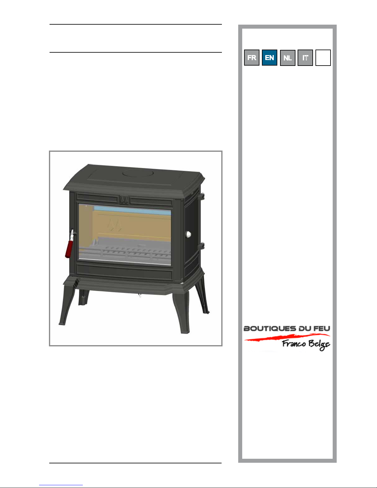
Monte Carlo
Rue Orphée Variscotte
59660 MERVILLE
Téléphone : 03 28 43 43 22
Fax : 03 28 43 43 60
Wood stove
NF EN 13240 : 2001 - EN 13240/A2 : 2005
Model : 134 12 07
Output : 11,5 kW
Description of the appliance
Installation instructions
Operating instructions
Spare parts
Warranty certicate
Document n°1291-8
22/03/2011
Technical manual
to be saved
by the user
for future reference
Subject to modications.
Page 2

Monte Carlo - réf. 134 12 07
2 Technical manual "1291"
Package ......................................................p. 3
General characteristics .................................p. 3
Description .................................................p. 3
Principle of operation ...................................p. 3
Warning to the user .....................................p. 4
The room ....................................................p. 4
Chimney .....................................................p. 5
Assembly of ue spigot ................................p. 5
Chimney connector ......................................p. 5
Pre-utilisation check ....................................p. 6
Maintenance of the chimney.........................p. 6
Removing and replacing the ue bafe .........p. 6
Fuel .............................................................p.7
Lighting ......................................................p. 8
Operating procedure ....................................p. 8
Cleaning .....................................................p. 8
Maintenance of the chimney.........................p. 8
Maintenance of the stove body .....................p. 8
Recommendations ........................................p.8
Trouble shooting .........................................p. 9
FRANCO BELGE congratulates you on your choice.
FRANCO BELGE, guarantees the quality of its appliances and is committed to meet
its customers’ needs.
FRANCO BELGE, which can boast a 80-year experience in the industry of heating devices,
uses state-of-the-art technologies
to design and manufacture its whole range of products.
This document contains instructions on how to install your appliance and make full use of
its functions, both for your comfort and safety.
CONTENTS
Product information .................................................................................................................... p. 3
Installation instructions ............................................................................................................... p. 4
Instructions for user ....................................................................................................................p. 7
Spare parts ..................................................................................................................................p. 11
Page 3
Monte Carlo - réf. 134 12 07
Technical manual "1291" 3
1.1. Package
• 1 package : Stove complete.
1.1. Optional equipment
• Kit air intake
1.3. General characteristics
1.4. Description
Stove, in conformity NF EN 13240:2001 - 13240/
A2:2005.
• Intermittent-burning heating appliance.
• Detachable ue spigot for rear or top chimney
connection.
• Front loading door tted with large refractory glass
panel.
• Loading door with a side opening (right of the
appliance)
• Adjustable air controls for controlling the burning
rate.
• Large ash-pan.
• Air wash system
• "Easy start" system
• Outside air inlet connexion diameter 100mm. If the
outside air inlet is connected to the appliance, it is not
necessary to foreseen additional air inlets in the room,
the Monte Carlo becoming fully “airtight".
• Long lasting burning cycle, when the appliance is
loaded with 8,3 kg of dry wood (air inlet closed) with
a 6 Pa, draught, it runs for 8 h 30.
Reference ........................................134 12 07
Nominal output .................................... kW 11,5
Chimney draught required ...................... Pa 12
Grate dimensions
- width ............................................... mm 735
- depth ............................................... mm 608
- height .............................................. mm 804
Log dimensions
- Lenght maxi .......................................cm 55
Ash pan capacity ................................litres 8,9
Net weight ............................................ kg 180
heated Volume ..................................... m3 460
Efciency ...............................................% 79
Co (13% O2) .........................................% 0,28
Flue gas temperature ........................... °C 320
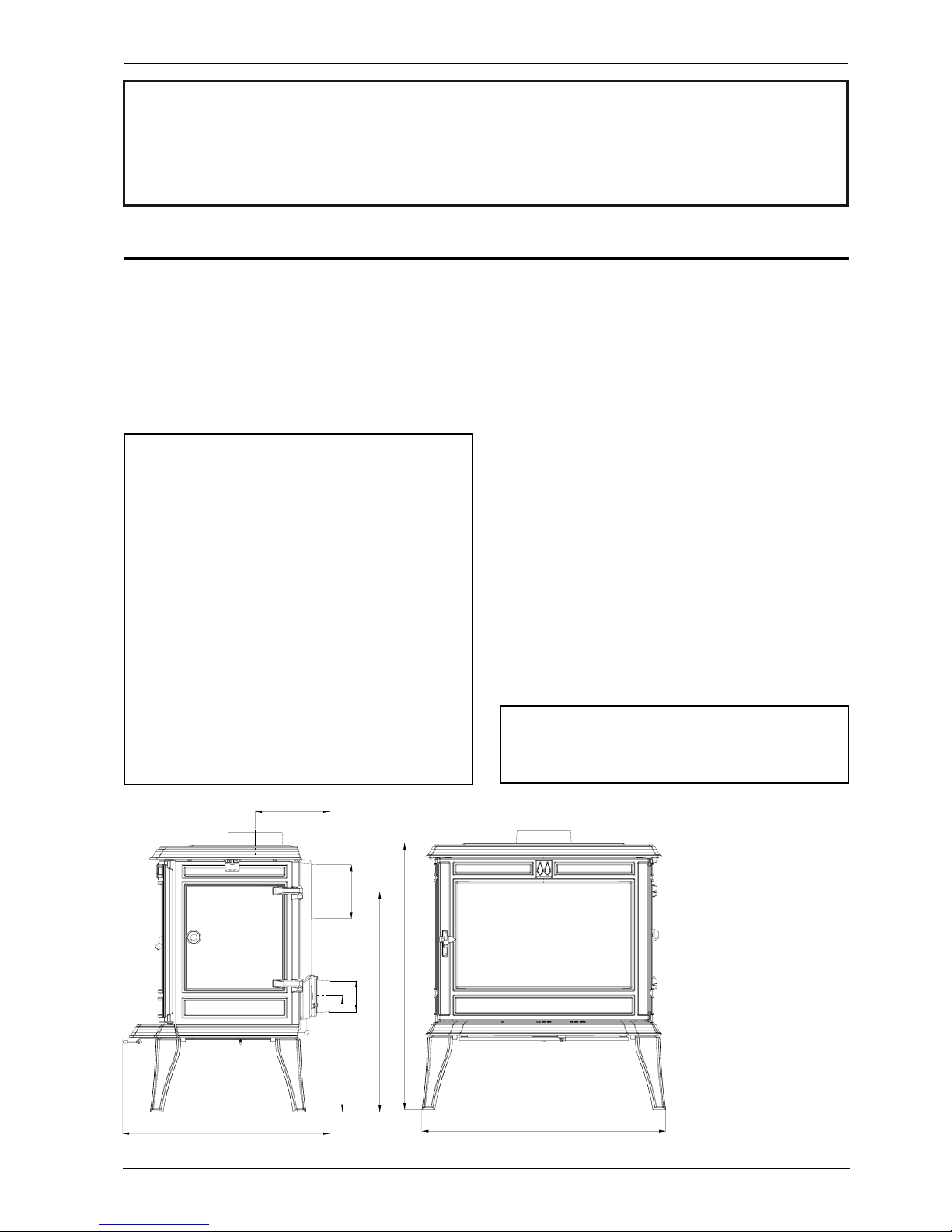
Figure 1 - Dimensions in mm
1.5. Principle of
operation
The “Monte Carlo” is
designed for operation
with the door closed.
Heat is mainly diffused
by radiation, through the
window and body of the
appliance.
Combustion is carried
out in a hot hearth with
the primary air injected
through the bafe and
the grate.
Note : the performances indicated result from tests carried
out in accordance with standard NF EN 13240:2001 -
13240/A2:2005, with logs 33 cm length, loading of 2,78 kg
and draught of 12 Pa.
664
224
608
Ø 153
349
Ø 100
804
735
1. Product information
This appliance is meant to burn wood safely
WARNING
Incorrectly installed, this appliance can be dangerous and possibly cause serious accidents.
We recommend that you engage the services of a professional engineer for its installation
and the regular maintenance requirements
Page 4
Monte Carlo - réf. 134 12 07
4 Technical manual "1291"
2.1 Warning to the user
All the local and national regulations, and
in particular those relating to national and
European standards, must be observed when
installing the appliance.
An incorrectly installed heating appliance can
cause serious accidents (chimney res, burning of
plastic insulation materials, in partition walls, etc.).
The insulation of both the appliance and the
exhaust gas pipe has to be reinforced and
done according to the Standards and the Bui lding
Regulations for safety reasons.
Failure to respect the mounting instructions leads to
engage the responsibility of the one doing the
installation.
The manufacturer’s responsibility shall be limited to
the supply of the equipment.
2.2. The room
Ventilation
: For satisfactory appliance operation
with a natural draught, check that sufcient air for
combustion is available in the room. in houses equipped
with one VMC (controlled mechanical ventilation), this
one aspire and renew the ambient air ; In this case,
the residence is under sl ight low pressure and a nonsealable external air intake must be installed in addition
to the chimney itself, at least 50 cm² in section. If the
outside air inlet is connected to the appliance, it is not
necessary to foreseen additional air inlets in the room,
the Monte Carlo becoming fully “airtight"
Position of the unit
: For new installations, select a
central position within the house, to provide a good
heat distribution around the building.
The heat distribution towards the other rooms will be
made through the communicating doors. These
rooms must be in negative pressure or must include
ventilation gratings.
Floor and walls
: Make sure there are not combustible
or covered with combustible material.
Otherwise it must necessary to install a noncombustible protection.
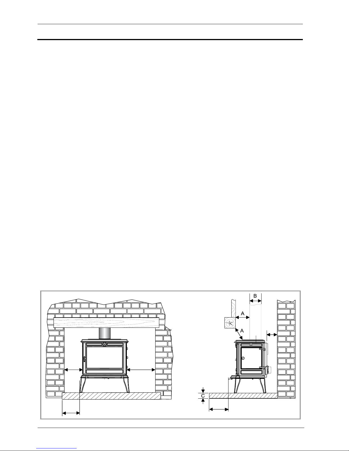
There must be a clearance of at least 150 mm at each
side of the appliance and at the back of the appliance
from a non-combustible wall.
This distance must be extended to a minimum
clearance of 400 mm from any combustible materials.
This measurement may be reduced to a minimum gap
of 50 mm when the non-combustible wall is at least
200 mm thick.
There should ideally be a minimum gap of 300 mm at
the right hand side of the stove, this will ensure the
best possible access to the loading door.
When using a single wall ue pipe, there must be a
clearance (A) of at least three times its diameter (B)
from any combustible materials.
If the appliance has to be located in an opening, this
distance must be extended to a minimum clearance
(A) of 450 mm from the pipe or the stove body to any
combustible materials.
Hearth
: The appliance must stand on a reproof
hearth.
It is possible to provide a hearth made of non
combusible board/sheet material or tiles at least 12 mm
thick. Constructional hearths should be constructed of
solid non combustible material at least 125 mm thick
(including the thickness of any non combustible oor
under the hearth).
The hearth must protrude at least 400 mm in front of
the stove and 150 mm each side.
If the hearth is constructed on timber, there must be a
clearance of at least 250 mm from the timber to the
top surface of the hearth.
When using a single wall ue pipe, there must be a
2. Installation instructions
400
150
490
150
150
Figure 2 - Clerances
Page 5

Monte Carlo - réf. 134 12 07
Technical manual "1291" 5
clearance (A) of at least 450 mm from any combustible
materials (timber mantel, girder).
See section J of the Building regulations.
2.3. Chimney
Existing ue
: The chimney must comply with Current
Building Regulations. If in doubt, consult your Dealer
or local Building Inspector.
- The ue must be in good condition and must provide
sufcient draught (refer to technical details p. 3).
- The ue must be suitable for the installation of solid
fuel burning appliances and comply with Current
Building Regulations.
- The ue must be clean. It should be swept to remove
soot and dislodge tar deposits.
- The ue must be well insulated. If the ue inner wall
surfaces are cold, a good thermal draw is impossible
causing condensation problems (tar formation etc) to
occur.
- The ue must not be shared with other appliances.
- The chimney must be at least 4.5 m (15 ft high).
- In case of a at roof or when the roof gradient is
lower than 15°, the stack must be 1,2 m (4 feet) high
at least.
- If the chimney has any down draught tendency, due
to its position in relation to nearby obstacles, then an
anti-down draught cowl must be installed on the
chimney or the chimney height must be increased.
- If the decompression in the chimney is excessive, a
draught stabiliser must be installed.
Chimney to be built / new ue
: The chimney
must comply with Current Building Regulations. If in
doubt, consult your Dealer or local Building Inspector.
- The appliance must not support the weight of the
ue.
- Consult a chimney specialist for advice on suitable
ue systems for solid fuel appliances.
- It must be distant from any combustible material
(walls, cross members)
- It must permit an easy sweeping.
2.4. Assembly of ue spigot
The stove is supplied with a connection ue spigot
with an inner diameter of 153 mm.
2.4.1. Smoke exit at rear (gure 3)
- Remove the ue bafe (§ 2.8).
- Fit on the top: the blanking plate 3, the rope 2, the
clamp with the provided screws.
- Fit on the rear appliance : the ue collar 1, the rope
2 with the provided screws.
- Replace the ue bafe (§ 2.8).
2.4.2. Smoke exit on the top (gure 4)
- Remove the ue bafe (§ 2.8).
- Fit on the rear appliance : the blanking plate 3, the
rope 2, the clamp 4 with the provided screws.
- Fit on the top : the collar collar 1, the rope 2 with the
provided screws.
- Replace the ue bafe § 2.8).
2.5. Chimney connector
The connection to ue must be carried out according
to local building regulations.
- The stove must be installed as close as possible to
the chimney.
- The connector pipe must be approved for installation
with combustion products (either 24 ga. black painted
or blued steel or 316 grade 20 ga. Stainless steel or
1 mm vitreous enamelled steel).
- Pipe diameter must not be less than the appliance
spigot diameter. Otherwise the reducing must be
1 diameter lower than the ue spigot and be situated
as distant as possible from the ue connection of the
appliance.
- The connection can be either vertical or horizontal.
For horizontal connections, avoid right angle bends.
- The join between the connection pipe and the
Figure 4 - Smoke exit on the topFigure 3 - Rear flue outlet
3
1
2
5
1
2
6
5
2
3
4
6
4
1 - Flue collar
2 - Ceramic
rope
3 - Blanking
plate
4 - Clamp
5 - Screw
(5 x 30)
6 - Suppl. Flue
bafe
1 - Flue collar
2 - Ceramic
rope
3 - Blanking
plate
4 - Clamp
5 - Screw
(5 x 30)
6 - Suppl. Flue
bafe
Page 6

Monte Carlo - réf. 134 12 07
6 Technical manual "1291"
stovepipe, and the ue, must be leak tight.
- For the premises equipped with a mechanical
controlled ventilation, the airtightness has to prevent
the exhauster drawing out the smokes from the
exhaust gas pipe.
- The connection pipe and any draught stabiliser
must have access for cleaning.
2.6. Pre-utilisation check
Check the condition of the ller seals, that the door
closes correctly , that the window is not damaged, that
the smoke passages are not obstructed by pieces of
packaging or removable parts.
Make sure that all removable parts are correctly
installed.
Note : all gaskets ceramic ropes, seals, are consumable
parts and must be changed on a regular basis by the
user.
2.7. Maintenance of the Chimney
Very important : To avoid accidents (chimney re,
etc.), regular maintenance should be carried out.
If the stove is regularly used, the chimney should
be swept several times per year, together with the
stovepipe connection section.
If the chimney catches re, you must cut off
the ue draught, close the doors and windows,
hatches and keys and call the Fire Brigade
without delay.
DO NOT OPEN THE DOOR OF THE APPLIANCE
(OR AIR INLET) UNDER ANY CIRCUMSTANCES.
Chimney condition should be checked at least
once per year by a professional engineer.
2.8. Removing and replacing the ue
bafe
(gure 5 et 6)
- Open the front door
- Remove the fuel retainer
- Remove the 2 screws (#1)
- Remove the 2 screws (#2)
- Remove the ue bafe (#3)
Removing and replacing the ue bafe, if needed, if
must be necessary, replace 2 gasket (see p. 12 n°15)
and replace the ue bafe in the reverse order.
Figure 5 - Removing the flue baffle
Figure 6 - Replacing the parts
3
2
1
3
2
1
Page 7

Monte Carlo - réf. 134 12 07
Technical manual "1291" 7
3. Instructions for user
All the local and national regulations, and
in particular those relating to national and
European standards, must be observed when
using the appliance.
Don’t run the stove in mild weather with coal ! Under
certain circumstances (e.g. fog and repeated thaw)
the chimney will not draw sufciently well and thus be
at the origin of asphyxia.
3.1. Fuel
This appliance is not an incinerator.
- Use hard wood logs, which have been cut for at least
two years and stored, under a ventilated shelter
(Humidity < 20 %)
- Hardwood has a higher caloric value per cu metre.
- Large logs must be split and cut to an useful length,
before being stored in a sheltered and ventilated place.
• Recommended fuel : Wood
Use hard wood logs, which have been cut for at least
two years and stored, under shelter.
Hardwood has a higher caloric value per cu metre
(oak, ash, maple, birch, elm, beech, etc.).
Large logs must be split and cut to a usable length,
before being stored in a sheltered and ventilated place.
• Not recommended as fuel :
- “Green wood”. Green or damp wood reduces stove
efciency and soils the glass, the internal walls and
the ue (soot, tar, etc.).
- “Used timbers”. Burning treated wood (railway
sleepers, telegraph poles, offcuts of plywood or chip
board, pallets, etc.) quickly clogs the ue ways (soot,
tar, etc.), pollutes the environment (pollution and
smell, etc.) and cause the re to burn too quickly and
overheat.
- “Green wood” and “recovered wood” can eventually
cause a chimney re.
• Prohibited fuel : Homere and any form of
bituminous coal or petroleum based coke.
The manufacturer will not be responsible for
damages on parts of the appliance due to the use
of prohibited fuel or due to an alteration of the
appliance or its installation. Only use replacement
parts supplied by the manufacturer.
Position A : eases the ignition and the picking
up of the combustion. for an optimal use, do
not leave the handle in this position more than
10 minutes.
Position B : low setting (the handle is in the
middle).
Position C : high setting.
In normal use, the air inlet handle should always
been located between position B and C.
D : Opening/closing the main door
E : Opening/closing the main door
Figure 7 - Operating devices
A
B
C
M
D
E
Page 8

Monte Carlo - réf. 134 12 07
8 Technical manual "1291"
3.2. Lighting
(
Figure 7)
- Slide the air control (position C or position A for a
easier lighting ).
- Open the front door and lay relighters or rolled up
newspapers on the grate with a reasonable quantity,
if necessary, of dry kindling wood. Place 2 or 3 small
logs on top.
- Light the newspaper or relighters using a long taper
and close the door.
Note :When the re is lit for the rst time, the
stove may give off fumes from the new paint. This
is normal but ensure the room is well ventilated
during the rst few hours of operation.
The burning rate can now be adjusted by moving
the air control to the right. Experience will show
you which settings are best for your situation.
3.3. Operating procedure
The appliance must function with the suitably
closed doors (rep. D et E).
The burning rate (position M) can be adjusted by
the air control ap. Experience will show you which
settings are best for your situation.
The airwash system works with the airslide. When the
airslide is full open the system works at its strongest
efciency (position C).
The more closed down the airslide is, the less effective
the airwash will be (when shut down completely, the
airwash system can not function).
Loading the fuel :
It is advisable to wait for the re to be reduced to hot
embers before re-loading. The door should also be
opened slowly when re-loading.
The minimum reloading interval for nominal heat
output is 45 mn.
- The logs must be placed on the glowing embers.
- For a briskly burning re, there should always be at
east two logs in the re. The re will burn better if
there are several logs.
- For a slower burning re (for example, at night),
select larger logs.
- Close the loading door (E).
- Open the lighting ap for a while.
3.4. Cleaning
It is essential to keep the grate free from a heavy build
up of ashes.
REMEMBER TO BURN SOLID FUEL CORRECTLY,
AlR SHOULD BE ALLOWED TO FLOW FROM THE
ASH PIT AREA THROUGH THE GRATE AND
THROUGH THE FUEL. IF THE GRATE OR ASH PAN
ARE CONGESTED, THE PERFOMANCE WILL BE
EFFECTED.
If burning solid fuel, always empty the ash pan at least
once a day or whenever it is full of ashes. Never allow
the ashpan to overll allowing ash to be in contact with
the underside of the grate. If this condition is allowed,
the grate will wear out pre-maturely.
3.5. Maintenance of the Chimney
Very important : In order to avoid any incident
carried out regularly.
If the appliance is regularly used, the chimney
should be swept several times per year, together
with the stovepipe connection section.
If the chimney catches re, you must cut off
the ue draught, close the doors and windows,
hatches and keys and call the Fire Brigade
without delay.
DO NOT OPEN THE DOOR OF THE APPLIANCE
(OR AIR INLET) UNDER ANY CIRCUMSTANCES.
Chimney condition should be checked at least once per
year by a professional engineer.
3.6. Maintenance of the stove body
• The appliance must be cleaned regularly , together
with the connecting pipe and the ue pipe.
• Remove all deposits from the combustion chamber
and clean the grate area.
• The vitro ceramic glass can only be cleaned using a
soft cloth and stove glass cleaner, available from your
Franco Belge Dealer. DO NOT USE ABRASIVES
• The vitro ceramic glass resists a temperature of
750°C.
If the glass should be broken, it is recommended that
only an original factory replacement should be tted.
• Check that there are no obstructions before relighting
after a long period of disuse.
• The appliance must not be used with a ue serving
several appliances.
• To maintain the grates ventilation free of any
obstruction,
For enamelled nishes, the stove body can be cleaned
using a soft cloth either dry, or slightly damp with a
very mild detergent.
NEVER CLEAN ENAMEL SURFACES WHILST
THE STOVE IS HOT.
The cast iron body panels of non-enamelled stoves can
be cleaned with a proprietary stove cleaner or
re-sprayed / touched up using a stove paint. These
products are available from your Franco Belge Dealer.
3.7. Recommendations
This room heater is a high heat producing appliance
and may cause severe burns if touched on the glass
front door, or on top directly over the burner.
The stove may still be HOT even when re has burnt
out.
Keep children away
Page 9

Monte Carlo - réf. 134 12 07
Technical manual "1291" 9
3.8. Trouble Shooting
Problem
Probable causes - ACTION
Fire difficult to start
Fire goes out
Wood green, too damp or poor
quality.
- Use the recommended fuel.
Logs are too big. - To light the fire, use small, very dry twigs. To
maintain the fire, use split logs.
Air starvation. - Open lower air controll and top air control
lever.
Insufficient draught. - Check that the flue is not obstructed, sweep
it if necessary
- Seek advice from a chimney specialist.
Fire burns too quickly.
Too much draught - Ensure that the lower air control is closed
- Partially close the top air control lever.
Excessive draw. - Install a draught stabiliser. Consult your
Dealer.
Poor quality wood. - Do not continuously burn small wood, sticks,
bundles, carpentry offcuts (plywood, pallets),
etc.
Smokes when lighting up.
Flue duct is cold. - Burn paper and kindling wood to increase
heat.
Room is in decompression. - In houses equipped with mechanical
ventilation, partly open a window until the fire
is well established.
Smokes while burning.
Draught is insufficient. - Consult a chimney specialist.
- Check that the flue is not obstructed, sweep if
necessary.
Down draught.
- Install an anti-down draught cowl. Consult
your Dealer.
Room is in decompression. - In houses equipped with Mechanical
Ventilation, an outside air intake must be
installed for the chimney.
Low heat output.
Incorrect Fuels. - Use the recommended fuel.
: This sign means that you should
ask for a qualified engineer to do the
work.
Page 10

Monte Carlo - réf. 134 12 07
10 Technical manual "1291"
Notes
Page 11

Monte Carlo - réf. 134 12 07
Technical manual "1291" 11
4.Spare parts
When ordering spare parts, specify the stove type and serial number, including the colour index (on the
guarantee or identication plate), the name of the part and the part number.
Example : Wood stove "Monte Carlo”, ref. 134 12 07, color Y, top plate 352177 EF
A = 134 12 07 Y ; B = 134 12 07 L ; C = 134 12 07 B ; D = 134 12 07 E ; E = 134 12 07 P ; F = 1341207 C
N° Code ................................... Désignation ....................Type ............... A ........B .........C .........D ........ E ......... F ......... Qté
1 100939 ...............................Axle ..........................................................A ........B ..........C .........D ........ E ..........F .......... 02
2 101067 ...............................Cam pin ....................................................A ........ B ..........C .........D ........ E ..........F .......... 01
3 101073 ...............................Sliding door axle ........................................A ........B ..........C .........D ........ E ..........F .......... 02
4 101074 ...............................Axle ..........................................................A ........B ..........C .........D ........ E ..........F .......... 01
5 105632 ...............................Firebrick ....................................................A ........ B ..........C .........D ........ E ..........F .......... 01
6 105634 ...............................Firebrick ....................................................A ........ B ..........C .........D ........ E ..........F .......... 01
7 105635 ...............................Firebrick ....................................................A ........ B ..........C .........D ........ E ..........F .......... 01
8 110403 ...............................Hinge pin.......................... 6x35 .................A ........ B ..........C ......... D ........ E ..........F .......... 02
9 105006 ...............................Gasket.............................. Ø 15 .................A ........ B ..........C .........D ........ E ..........F ....2,53 m
10 101811 ...............................Ring ..........................................................A ........ B ..........C .........D ........ E .......... F .......... 01
11 616121 ...............................Circulation duct ..........................................A ........ B ..........C ......... D ........ E ..........F .......... 02
12 134253 ...............................Bushing .....................................................A ........ B ..........C .........D ........ E ..........F .......... 02
13 142881 ...............................Gasket.......................................................A ........ B ..........C .........D ........ E .......... F .......... 02
14 181630 ...............................Gasket.......................................................A ........ B ..........C .........D ........ E .......... F ..... 1,5 m
15 142898 ...............................Gasket.......................................................A ........ B ..........C .........D ........ E .......... F .......... 02
16 158637 ...............................Handle ......................................................A ........B ..........C .........D ........ E ..........F .......... 01
17 161027 ...............................Touch-up paint .................. (J) ............................... B .......................................................... 01
17 161047 ...............................Touch-up paint .................. (B) ...........................................C .............................................. 01
17 161061 ...............................Touch-up paint .................. (E)....................................................... D .................................. 01
17 161025 ...............................Touch-up paint .................. (L) .................................................................. E ....................... 01
17 161059 ...............................Touch-up paint .................. (C) ..............................................................................F .......... 01
18 166003 ...............................Spring .............................. 11x15 ...............A ........ B ..........C .........D ........ E ..........F .......... 03
19 175013 ...............................Suppl. ue bafe ........................................A ........ B ..........C .........D ........ E ..........F ............ 0
20 179628 ...............................Regulator shaft ..........................................A ........ B ..........C ......... D ........ E ..........F .......... 01
21a 181604 ...............................Ceramic rope .................... 10x4 .................A ........B ..........C .........D ........ E ..........F ..... 0,5 m
21b 181604 ...............................Ceramic rope .................... 10x4 .................A ........B ..........C ......... D ........ E ..........F ..... 0,5 m
22a 181632 ...............................Gasket.............................. Ø 6 ...................A ........ B ..........C ......... D ........ E ..........F ....1,75 m
22b 181632 ...............................Gasket..............................Ø 6 ...................A ........ B ..........C ......... D ........ E ..........F ....0,30 m
23 181633 ...............................Gasket.............................. Ø 10 .................A ........ B ..........C .........D ........ E ..........F ....1,05 m
24 188890 ...............................Refractory glass ................ 540x333 ...........A ........ B ..........C .........D ........ E ..........F .......... 01
25 189103 ...............................Screw ...............................27x8x6 .............A ........ B ..........C ......... D ........ E ..........F .......... 04
26 189104 ...............................Screw ...............................6x22 .................A ........ B ..........C .........D ........ E ..........F .......... 02
27 189141 ...............................Screw ........................................................A ........B ..........C .........D ........ E ..........F .......... 01
28 189142 ...............................Screw ........................................................A ........B ..........C .........D ........ E ..........F .......... 01
29 222583 ...............................Flue bafe .................................................A ........ B ..........C .........D ........ E .......... F .......... 01
30 222620 ...............................Suppl. ue bafe ........................................A ........ B ..........C .........D ........ E ..........F .......... 00
31 224058 ...............................Ash-pan ....................................................A ........ B ..........C .........D ........ E ..........F .......... 01
32 261010 ...............................Heat shield ................................................A ........ B ..........C .........D ........ E .......... F .......... 01
33 228629 ...............................Square ......................................................A ........B ..........C .........D ........ E ..........F .......... 01
34 231303 ...............................Square ......................................................A ........B ..........C .........D ........ E ..........F .......... 01
35 237429 ...............................Reducing plate ...........................................A ........ B ..........C .........D ........ E ..........F .......... 02
36 259015 ...............................Fixing plate ................................................A ........B ..........C .........D ........ E ..........F .......... 04
37 262615 ...............................Heat shield ................................................A ........ B ..........C ......... D .........E .........F .......... 01
38 265605 60 ...........................Knob .........................................................A ........ B ..........C ........ D ........ E .......... F .......... 01
39 270416 ............................... Air control ap ...........................................A ........B ..........
C ........ D ........ E .......... F .......... 01
40 277609 ............................... Knob .........................................................A ........B ..........C ........ D ........ E .......... F .......... 01
41 406816 ............................... Clamp .......................................................A ........ B ..........C ........ D ........ E .......... F .......... 01
42 900992 ............................... Door lock ..................................................A ........B ..........C ........ D ........ E ..........F .......... 01
43 300140 MK ..........................Leg ......................................................................................................................F .......... 04
43 300140 RH .......................... Leg ......................................................................................................... E ....................... 04
43 300140 RJ ........................... Leg ...................................................................................C ............................................. 04
43 300140 RP ........................... Leg ..............................................................................................D .................................. 04
43 300140 AB ........................... Leg ...........................................................A ..................................................................... 04
43 300140 77 ...........................Leg ......................................................................B .......................................................... 04
44 300433 AB ........................... Base .........................................................A ........ B ..........C ........ D ........ E .......... F .......... 01
45 303516 MK ..........................Loading door ........................................................................................................F .......... 01
45 303516 RH .......................... Loading door ........................................................................................... E ....................... 01
45 303516 RJ ........................... Loading door .....................................................................C ............................................. 01
45 303516 RP ........................... Loading door ................................................................................ D .................................. 01
45 303516 AB ........................... Loading door .............................................A ..................................................................... 01
45 303516 77 ...........................Loading door ........................................................ B .......................................................... 01
Page 12

Monte Carlo - réf. 134 12 07
12 Technical manual "1291"
Figure 8 - Stove - exploded view
21b
46
9
61
41
56
53
15
15
19
5
11
55
12
48
60
67
21a
47
22b
35
35
1
25
18
25
18
39
36
29
66c
40
34
3
7
6
30
14
54
59
51
31
36
24
22a
2
16
33
26
64
26
58
50
57
43
20
38
25
37
18
62
43
43
44
17
52
8
8
45
4
10
23
28
12
13
13
49
1
27
42
63
32
65a
65b
66b
66b
66a
Page 13

Monte Carlo - réf. 134 12 07
Technical manual "1291" 13
A = 134 12 07 Y ; B = 134 12 07 L ; C = 134 12 07 B ; D = 134 12 07 E ; E = 134 12 07 P ; F = 1341207 C
N° Code Désignation Type A B C D E F Qté
46 303718 MK ..........................Blanking plate ....................................................................................................... F ............. 01
46 303718 RH ..........................Blanking plate ............................................................................................E ......................... 01
46 303718 RJ ...........................Blanking plate ..................................................................... C ...............................................01
46 303718 RP ...........................Blanking plate ............................................................................... D .....................................01
46 303718 AB ...........................Blanking plate .............................................A .......................................................................01
46 303718 77 ...........................Blanking plate ........................................................ B ............................................................01
47 303826 MK ..........................Flue collar .......................... Ø 153 int. ....................................................................F ............ 01
47 303826 RH .......................... Flue collar ..........................Ø 153 int. .......................................................E ........................01
47 303826 RJ ..........................Flue collar .......................... Ø 153 int. ................................ C ...............................................01
47 303826 RP .......................... Flue collar ..........................Ø 153 int. ...........................................D .................................... 01
47 303826 AB .......................... Flue collar ..........................Ø 153 int. .........A.......................................................................01
47 303826 77 ..........................Flue collar ..........................Ø 153 int. ....................B ...........................................................01
48 303859 AB .......................... Flue collar ...................................................A.........B .........C ........C .........E ..........F ............01
49 306270 AB .......................... Back wall ....................................................A.........B ......... C ........ D .........E ..........F ............01
50 307441 AB .......................... Fuel retainer ................................................A.........B .........C ........D .........E ..........F ............01
51 309235 AB .......................... Grate ..........................................................A.........B .........C ........D .........E ..........F ............ 01
52 310740 MK ..........................R. side panel ..........................................................................................................F ............ 01
52 310740 RH .......................... R. side panel .............................................................................................E ........................01
52 310740 RJ ..........................R. side panel ...................................................................... C ...............................................01
52 310740 RP .......................... R. side panel .................................................................................D .................................... 01
52 310740 AB .......................... R. side panel ...............................................A.......................................................................01
52 310740 77 ..........................R. side panel ..........................................................B ...........................................................01
53 310835 MK ..........................L. side panel ...........................................................................................................F ............01
53 310835 RH .......................... L. side panel ..............................................................................................E ........................01
53 310835 RJ ..........................L. side panel ....................................................................... C ............................................... 01
53 310835 RP .......................... L. side panel ..................................................................................D .................................... 01
53 310835 AB .......................... L. side panel ................................................A.......................................................................01
53 310835 77 ..........................L. side panel ...........................................................B ...........................................................01
54 315616 AB .......................... Air duct .......................................................A.........B .........C ........D .........E ..........F ............ 01
55 324503 AB .......................... Sealing plate ...............................................A.........B .........C ........D .........E ..........F ............ 01
56 326601 AB .......................... Suppl. ue bafe .........................................A.........B ......... C ........ D .........E ..........F ............01
57 327911 MK ..........................Ash pan guide ........................................................................................................F ............01
57 327911 RH .......................... Ash pan guide ...........................................................................................E ........................01
57 327911 RJ ..........................Ash pan guide ....................................................................C ............................................... 01
57 327911 RP .......................... Ash pan guide ...............................................................................D .................................... 01
57 327911 AB .......................... Ash pan guide .............................................A.......................................................................01
57 327911 77 ..........................Ash pan guide ........................................................B ...........................................................01
58 331133 MK ..........................Main door ..............................................................................................................F ............ 01
58 331133 RH .......................... Main door .................................................................................................E ........................01
58 331133 RJ ..........................
Main door ..........................................................................C ............................................... 01
58 331133 RP .......................... Main door .....................................................................................D .................................... 01
58 331133 AB .......................... Main door ...................................................A....................................................................... 01
58 331133 77 ..........................Main door ..............................................................B ........................................................... 01
59 332005 AB .......................... Air duct .......................................................A.........B .........C ........D .........E ..........F ............ 01
60 332401 AB .......................... Supplementary plate ....................................A.........B .........C ........D .........E ..........F ............01
61 352177 MK ..........................Top plate ................................................................................................................F ............ 01
61 352177 RH .......................... Top plate ...................................................................................................E ........................ 01
61 352177 RJ ..........................Top plate ............................................................................C ............................................... 01
61 352177 RP .......................... Top plate .......................................................................................D ....................................01
61 352177 AB .......................... Top plate .....................................................A.......................................................................01
61 352177 77 ..........................Top plate ................................................................B ........................................................... 01
62 808001 ED .......................... Hand tool ....................................................A.........B .........C ........D .........E ..........F ............ 01
63 989017 ........................... Complete door .............................................A....................................................................... 01
63 989018 ........................... Complete door ........................................................B ...........................................................01
63 989019 ........................... Complete door .................................................................... C ............................................... 01
63 989020 ........................... Complete door ...............................................................................D .................................... 01
63 989021 ........................... Complete door ...........................................................................................E ........................01
63 989022 ........................... Complete door ........................................................................................................F ............ 01
64 181614 ........................... Rope .................................. Ø 9,5 ................A.........B .........C ........D .........E ..........F ............ 2,05 m
65a 181632 ..............................Rope .................................. Ø 6 ...................A ........B ......... C ....... D ..........E ..........F ............1,17 m
65b 181632 ..............................Rope .................................. Ø 6 ...................A ........B ......... C ....... D ..........E ..........F ............0,37 m
66a 181625 ..............................Gasket ............................... Ø 7 ...................A ........B ......... C ....... D .......... E ..........F ............2,37 m
66b 181625 ..............................Gasket ...............................Ø 7 ...................A ........B .........C ....... D .......... E ..........F ..............0,6 m
66c 181625 .............................. Gasket ............................... Ø 7 ...................A ........B .........C ....... D ..........E ..........F ..............0,5 m
67 181631 ..............................Gasket ...............................Ø 10 .................A ........B ......... C ....... D .......... E ..........F ............0,85 m
Page 14

Guarantee certificate
Legal guarantee
The specications, dimensions and information shown on our
documents are provided for information purposes only and
under no circumstances are binding upon the vendor.
With the aim of constantly improving our equipment, all
modications considered as necessary by our departments
may be made without notice.
The provisions of the present guarantee certicate are not
excluding or limiting the owner of the equipment’s rights,
concerning the legal guarantee regarding faults or hidden
vices which applies in all circumstances, in the conditions
detailed in articles 1641 and following of the civil code, and in
the country in which the equipment was purchased.
Contractual guarantee
Our equipment is guaranteed against faults and hidden
vices subject to the following conditions :
1) Installation and adjustment of the device by a professional
installer.
2) Observance of the instructions provided in our technical
documents and our installation/adjustment instructions.
3) The installation, use and maintenance of the device
carried out in conformity with the applicable standards and
legislation, and with the indications provided in the technical
instructions accompanying the device.
This guarantee covers the replacement, in our factory, of
parts recognised as being defective from the outset by our
“Guarantee Inspection” Department. Carriage and labour is
at the user’s cost. Moreover, if the repair or replacement of
parts covered by the guarantee is found to be too costly vis-
à-vis the price of the appliance, the decision to replace or
repair the appliance will be taken by the vendor.
Our guarantee is for 2 (two) years for all appliances, with
the exception of closed combustion replace and inserts for
which our guarantee is 5 (ve) years excluding the following :
1) Indicator lights, fuses, electrical elements and fans.
2) Parts subject to wear or in contact with high temperatures
namely: soles and burner grills, bottom plates bafes, ash
pans, paintwork and surface treatments for decorative
parts. Also excluded from this guarantee are seals and
windows.
3) Any damage which may result from the use of the appliance
with a fuel other than that stipulated in our instructions.
4) Damage occurring to parts caused by elements outside the
appliance (down draught, storm damage, damp, abnormal
pressure or vacuum, heat shocks, etc.).
5) Damage to electrical parts caused by plugging in and
using the appliance on a mains system, the voltage of which
(measured at the entrance to the appliance) is 10% above or
below the nominal voltage of 220 V.
Exclusion of liability
In the case of a product manufactured at the client’s request,
under no ci rcumstances may we, as a subcontractor, be
considered liable vis-a-vis the client or third parties for
defects arising from the installation or a design fault with the
item in question.
Name and address of the installer : .........................................................................................................................
..............................................................................................................................................................................
Telephone : ............................................................................................................................................................
Name and address of the customer : .........................................................................................................................
..............................................................................................................................................................................
Date of installation : ................................................................................................................................................
Model of the appliance :
134 12 07
Color : Y L B E P C
Serial number : ..............................................
• This certicate has to be completed and kept carefully.
In case of claims, send a copy of this to :
FRANCO BELGE
BP 73, 59660 MERVILLE, FRANCE.
 Loading...