

FRANCO BELGE Lorraine MF 121 13 01 Technical Manual
Contents
Description of the unit . . . . . . . . . . . . . . . . . . . . p. 3
Installation instructions . . . . . . . . . . . . . . . . . . . p. 4
Instructions for user . . . . . . . . . . . . . . . . . . . . . p. 6
List of components . . . . . . . . . . . . . . . . . . . . . . p. 9
Technical manual
to be saved
by the user
for future
reference
Document n° 280-3GB ~ 17/12/1997
Les Fonderies Franco-Belges
F 59660 MERVILLE
Téléphone : 03.28.43.43.43
Fax : 03.28.43.43.99
RC Hazebrouck 445750565B
Matériel sujet à modifications sans préavis
Document non contractuel.
Lorraine MF
Multifuel stove
Model : 121 13 01
Output : 12 kW
F
GB
Lorraine MF Multifuel stove Réf. 121 13 01
Contents
Description of the unit . . . . . . . . . . . . . . . . . . . . p. 3
Package . . . . . . . . . . . . . . . . . . . . . . . . . . . . p. 3
General characteristics . . . . . . . . . . . . . . . . . . . p. 3
Descriptif . . . . . . . . . . . . . . . . . . . . . . . . . . . p. 3
Principle of operation . . . . . . . . . . . . . . . . . . . . p. 3
Installation instructions . . . . . . . . . . . . . . . . . . . p. 4
Assembly of the flue collar and the blanking plates . . . p. 4
Installation . . . . . . . . . . . . . . . . . . . . . . . . . . p. 4
Siting the stove . . . . . . . . . . . . . . . . . . . . . . . . p. 4
The chimney . . . . . . . . . . . . . . . . . . . . . . . . . p. 4
Chimney connection . . . . . . . . . . . . . . . . . . . . . p. 5
Water connections . . . . . . . . . . . . . . . . . . . . . . p. 5
Check list before lighting stove . . . . . . . . . . . . . . . p. 5
Adjustment of the thermostat . . . . . . . . . . . . . . . . p. 5
Instructions for user . . . . . . . . . . . . . . . . . . . . . p. 6
Lighting the stove . . . . . . . . . . . . . . . . . . . . . . p. 6
Running the stove . . . . . . . . . . . . . . . . . . . . . . p. 7
Maintenance . . . . . . . . . . . . . . . . . . . . . . . . . p. 7
Care of the stove . . . . . . . . . . . . . . . . . . . . . . . p. 7
Cleaning the glass . . . . . . . . . . . . . . . . . . . . . . p. 7
Flue cleaning and summer time . . . . . . . . . . . . . . p. 7
Removing the oscillating grates . . . . . . . . . . . . . . p. 8
List of components . . . . . . . . . . . . . . . . . . . . . . p. 9
2 Notice de référence
Document n° 280-3GB ~ 17/12/1997
GB
Document n° 280-3GB ~ 17/12/1997
Réf. 121 13 01 Multifuel stove Lorraine MF
Notice de référence 3
WARNING
The appliance must be installed in compliance with Current Building Regulations.
Incorrectly installed, this appliance can be dangerous
and possibly cause serious accidents.
The manufacturer’s responsibility shall be limited to the supply of the equipment.
❑
1.Description of the unit
1.1. Package
- 1 package : Stove complete.
1.2. General characteristics
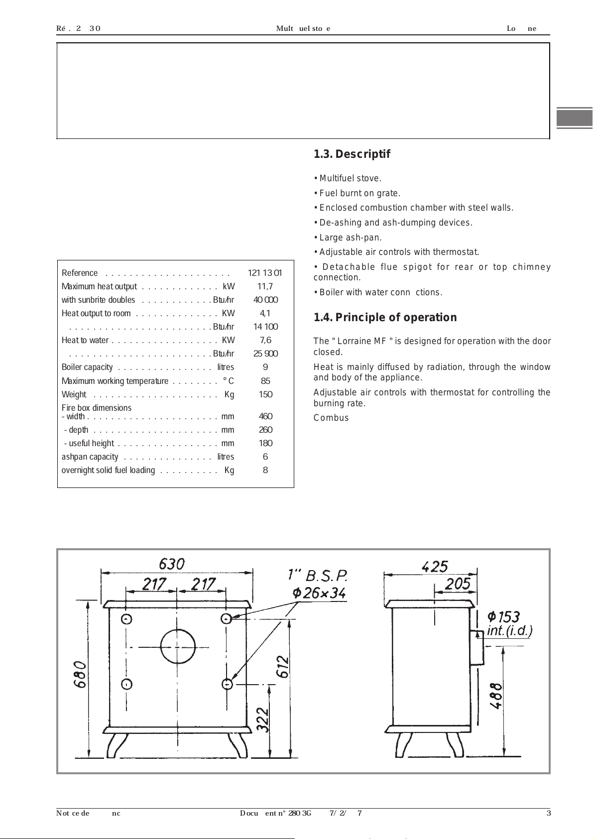
Reference . . . . . . . . . . . . . . . . . . . . . 121 13 01
Maximum heat output . . . . . . . . . . . . . kW 11,7
with sunbrite doubles . . . . . . . . . . . . Btu/hr 40 000
Heat output to room . . . . . . . . . . . . . . KW 4,1
. . . . . . . . . . . . . . . . . . . . . . . . Btu/hr 14 100
Heat to water . . . . . . . . . . . . . . . . . . KW 7,6
. . . . . . . . . . . . . . . . . . . . . . . . Btu/hr 25 900
Boiler capacity . . . . . . . . . . . . . . . . litres 9
Maximum working temperature . . . . . . . .°C 85
Weight . . . . . . . . . . . . . . . . . . . . . Kg 150
Fire box dimensions
- width . . . . . . . . . . . . . . . . . . . . . . mm 460
- depth . . . . . . . . . . . . . . . . . . . . . mm 260
- useful height . . . . . . . . . . . . . . . . . mm 180
ashpan capacity . . . . . . . . . . . . . . . litres 6
overnight solid fuel loading . . . . . . . . . . Kg 8
1.3. Descriptif
• Multifuel stove.
• Fuel burnt on grate.
• Enclosed combustion chamber with steel walls.
• De-ashing and ash-dumping devices.
• Large ash-pan.
• Adjustable air controls with thermostat.
• Detachable flue spigot for rear or top chimney
connection.
• Boiler with water connections.
1.4. Principle of operation
The " Lorraine MF " is designed for operation with the door
closed.
Heat is mainly diffused by radiation, through the window
and body of the appliance.
Adjustable air controls with thermostat for controlling the
burning rate.
Combustion occurs on the grates in a hot enclosed
combustion chamber. The thermostat regulates the
draught entry under the grates.❑
Figure 1 - Dimensions in mm
Lorraine MF Multifuel stove Réf. 121 13 01
2.Installation instructions
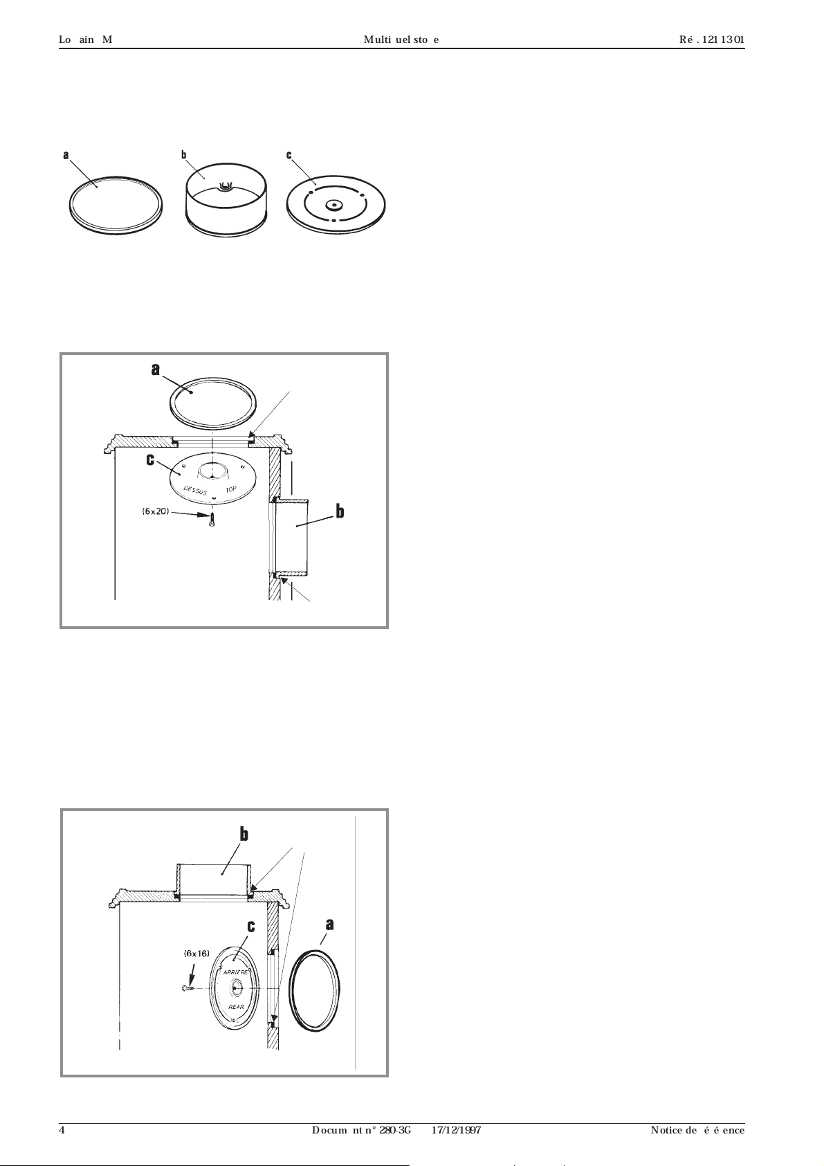
2.1. Assembly of the flue collar and the
blanking plates
The flue collar and the 2 blanking plates are assembling
deliver on the stove for smoke exit at rear.
Smoke exit at rear (fig. 3) :
The blanking plates are fitted on the top plate from factory,
fit the flue collar (3 bolts) with fire ciment.
Lift the top plate (2 bolts) and remove the rear heat schield.
airtight seal
2.2. Installation
Important : Before commencing the installation of your
new appliance it is recommended that the instructions are
read and understood.
Health and safety at work act 1974 :
The installer should comply with the Health and Safety at
Work Act 1974 and with particular reference to the
following.
Handling :
Adequate facilities should be provided for handling the
appliance.
Glass :
Extra care should be taken to avoid breakages.
Fire cement :
Care should be taken to avoid fire cement contacting the
skin. The material is caustic and in the event of contact
being made, wash off immediately with clean water.
Electrical :
If electrical components are to be used in the installation
system, all installation work must be carried out in
accordance with the Regulations for the Electrical
Equipment of Buildings. Care should be taken to conform
to the installation instructions of individual manufacturers.
Flues, combustion air supply and connection of the
appliance
Current Building Regulations and relevant Codes of
Practice must be observed.
The responsability of FRANCO-BELGE only affect the
supply of the appliance.
Fire ciment
Figure 3 - Rear flue outlet
For installation smoke exit on the top (fig. 4):
• Lift the top plate (2 bolt) and remove the rear heat shield.
• Remove the flue baffle (# 50, p. 11).
• Exchange the blanking plates with the flue collar,
ensuring that it is leaktight.
• Replace the flue baffle.
• Reinstall the rear covering and closed the exit position
with an iron plate.
• Refit the top plate.
airtight seal
Figure 4 - Top flue outlet
2.3. Siting the stove
The hearth on which the stove is to be installed must
comply with Current Building Regulations.
A fresh air inlet must be provided in order to allow efficient
combustion and to avoid a vacuum effect being created in
the room ; air extractors and fans must not be used in the
same room or adjoining room to the installation.
This stove is not designed to be built in, and an air space
of at least 150 mm must be left all around the stove.
Ensure that appliance and flue pipe are clear of
combustible materials.
The stove should be level. Sufficient access for chimney
sweeping and appliance cleaning must be provided.
2.4. The chimney
The chimney must be in good condition free from cracks
and blockages and should not have an excessive cross
sectional area. If problems are encountered expert advice
should be sought regarding the necessity of having the
chimney lined. Should it be found necessary to line the
chimney, a lining suitable for solid fuel must be used. If the
appliance is to be fitted in a room where there is no existing
chimney a prefabricated block chimney or a twin walled
insulated stainless steel flue to B.S 4543 can be used
either internally or externally. The internal diameter must
not be less than 150 mm (6 inches). These flues must be
fitted in accordance with the manufacturers instructions
and Building regulations.
Before connecting the appliance to an existing flue, the
flue must be swept and checked. In order for the appliance
to perform satisfactorily the chimney height should not be
less than 5 metres measured vertically from the outlet of
the stove to the top of the flue terminal. Should there be
excessive draught in the chimney it may be necessary to
fit a draught stabliliser.
4 Notice de référence
Document n° 280-3GB ~ 17/12/1997
 Loading...