

FRANCO BELGE Limousin Technical Manual
Description of the appliance
Installation instructions
Operating instructions
Spare parts
Warranty certificate
Technical manual
to be saved
by the user
for future reference
Document n° 1054-2 ~ 13/12/2000
Les Fonderies Franco-Belges
59660 MERVILLE
Phone : 03.28.43.43.43
Fax : 03.28.43.43.99
RC Hazebrouck 445750565B
Subject to modifications
LIMOUSIN
Wood stove
CGBfD-NFD35-376
Model : 134 10 12
Output : 10 kW

Product information . . . . . . . . . . . . . . . . . . . . . . . . . . . . . . . . . . . . . . 3
Package . . . . . . . . . . . . . . . . . . 3
Optional . . . . . . . . . . . . . . . . . . . 3
General characteristics . . . . . . . . . . 3
Description . . . . . . . . . . . . . . . . . 3
Principle of operation . . . . . . . . . . . 3
Installation instructions . . . . . . . . . . . . . . . . . . . . . . . . . . . . . . . . . . . . 4
The room . . . . . . . . . . . . . . . . . . 4
Flue . . . . . . . . . . . . . . . . . . . . . 4
Assembly of flue spigot
and blanking plates . . . . . . . . . . . . 4
Connection to flue . . . . . . . . . . . . . 5
Mounting the tray . . . . . . . . . . . . . 5
Chimney maintenance and sweeping . . 5
Instructions for user . . . . . . . . . . . . . . . . . . . . . . . . . . . . . . . . . . . . . . 6
Fuel . . . . . . . . . . . . . . . . . . . . . 6
Instruction for use with wood . . . . . . . 7
Instructions for use with solid fuel . . . . 7
Cleaning . . . . . . . . . . . . . . . . . . 7
Maintenance of the stove body . . . . . . 7
Trouble Shooting . . . . . . . . . . . . . . 8
Spare parts . . . . . . . . . . . . . . . . . . . . . . . . . . . . . . . . . . . . . . . . . . . 10
CONTENTS Page Page
FRANCO BELGE congratulates you on your choice.
FRANCO BELGE, which has been granted the ISO 9001 certification, guarantees the
quality of its appliances and is committed to meet its customers needs.
FRANCO BELGE, which can boast a 75-year experience in the industry of heating devices,
uses state-of-the-art technologies
to design and manufacture its whole range of products.
This document contains instructions on how to install your appliance and and make full
use of its functions, both for your comfort and safety.
Wood stove "LIMOUSIN"
2 Technical manual
Warning to the user
A wood stove should only be installed by competent personnel, in the strict
application of normal practices and all safety precautions.
An incorrectly installed wood stove can cause serious accidents (chimney fires,
burning of plastic insulation materials, in partition walls, etc.).
The manufacturers responsibility shall be limited to the supply of the equ ipment.
1.Product information
1.1. Package
1 package : Stove complete.
1.2.Optional
•Boiler
•Coal grate
1.3.General characteristics
Reference.................... 1341012
Maximumoutput...............kW 10
...................... Btu/hr 34000
Chimneydraftrequired........... Pa 10
Grate dimensi ons
-width ....................mm 540
-depth ....................mm 250
-usableheight................mm 200
Log dim ensions
-Lenght ................... cm 50
-Diameter .................. cm 10à16
Ashpancapacity ............. litres 6,8
Netweight .................. kg 160
Volumeheated ............... m
3
380
Autonomy ................... h 10
1.4. Description
Stove, CGBfD- NF D 35-375
C : Continuous-burning heating appliance.
G : Wood burnt on grate
B : Wood burning stove
f : Enclosed combustion chamber with refractory brick
walls.
D : Removable appliance, to be installed near a wall.
•Detachable flue spigot for rear or top chimn ey
connection.
•Detachable top for easy handling and cleaning (rear
smoke exit only).
•Adjustable air controls for controlling the burning rate.
•Spin wheel for lighting.
•Large ash-pan.
•Side loading door.
1.5.Principle of operation
The “ Limousin ” is designed for operation with the door
closed.
Heatis mainly diffused by radiation, through the window
and body of the appliance.
Combustion occurs on the grate, with draught entry
through the top of the combustion chamber when using
wood and under the grate when using coal.
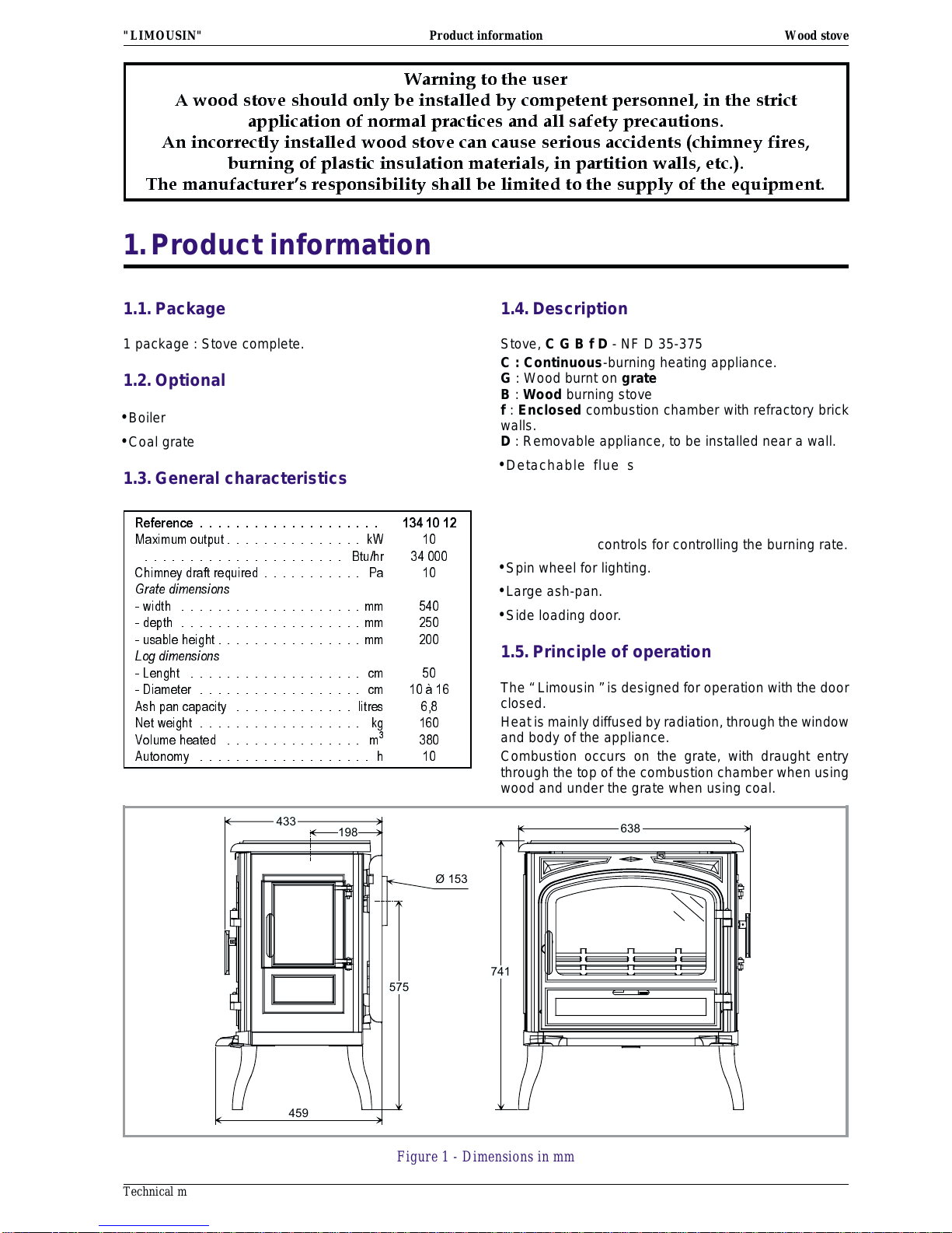
433
198
575
741
638
Ø 153
459
Product information
Figure 1 - Dimensions in mm
"LIMOUSIN" Wood stove
Technical manual 3
2.Installation instructions
2.1.The room
Ventilation :
For satisfactory operation with a natural draught, check
that sufficient air for combustion is available in the
room.
Chimney position :
For new chimney installations, select a central position
within the building, to provide a good heat distribution
around the building.
Hearth :
The hearth must be suitable for use with solid fuel
burning appliances and must comply with Current
Building Regulations. If in doubt, consultyour Dealer or
local Building Inspector.
Rear wall and ceiling :
The appliance must not be positioned close to
combustible materials, wall & ceiling surfaces etc.,
Consult your Dealer or local Building Inspector if in
doubt.
2.2.Flue
Existing flue :
- The flue must be in good condition and must provide
sufficient draught.
- The flue must be suitable for the installation of solid
fuel burning appliances and comply with Current
Building Regulations.
- The flue must be clean. It should be swept to remove
soot and dislodge tar deposits.
- The flue must be well insulated. If the flue inner wall
surfaces are cold, a good thermal draw is impossible
causing condensation problems (tar formation etc) to
occur.
- The flue must not be shared with other appliances.
- The recommended minimum flue height is 5 metres.
- If the chimney has any down draught tendency, due to
its position in relation to nearby obstacles, then an
anti-down draught cowl must be installed on the
chimney or the chimney height must be increased.
- If the decompression in the chimney is excessive, a
draught stabiliser must be installed.
- The flue must not be supported by the stove.
- Consult a chimney specialist for advice on suitable
flue systems for solid fuel appliances.
2.3.Assembly of flue spigot
and blanking plates
The stove is supplied with a connection flue spigot with
an inner diameter of 153 mm.
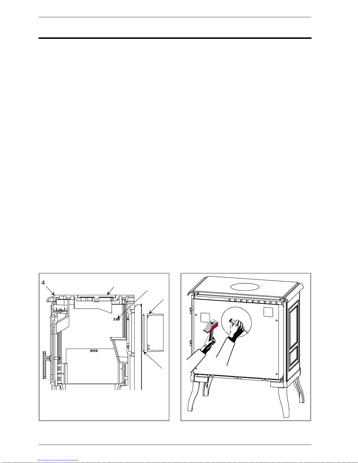
2.3.1. Smoke exit at rear
Figure 2
•Remove the top plate 4.
•Remove the flue baffle (# 37, fig. 7, p. 11).
•Fit the sealing rope 2 in the groove at rear and fix the
flue collar 1 with 3 bolts and washers supplied.
•Replace the flue baffle (# 37, fig. 7, p. 11).
•Replace the top plate.
•Remove the cut-out in the rear heat shield and re fit
(fig. 3)
1
2
3
4
5
Installation instructions
1 - Flue collar
2 -Ceramicrope
3 - Blanking plate
4 - Top plate
5 - Vis de 6 x 20
Figure 2 - Rear flue outlet
Figure 3 - Rear heat shield
Wood stove "LIMOUSIN"
4 Technical manual
 Loading...