

FRANCO BELGE Hekla 634 10 44, Hekla 634 10 45 Technical Manual
Description of the appliance
Installation instructions
Operating instructions
Spare parts
Warranty certificate
Document n° 1204-1 ~ 02/05/2005
STAUB FONDERIE
SARL with the capital of 6 359 540
Head Office Address
2, rue Saint Gilles
68230 TURCKHEIM
RCS Colmar
SIREN 444 881 953
Address
Administration and manufacturing
BP 73
59660 MERVILLE (FRANCE)
Telephone : 00 333 28 43 43 00
Fax : 00 333 28 43 43 99
Subject to modifications.
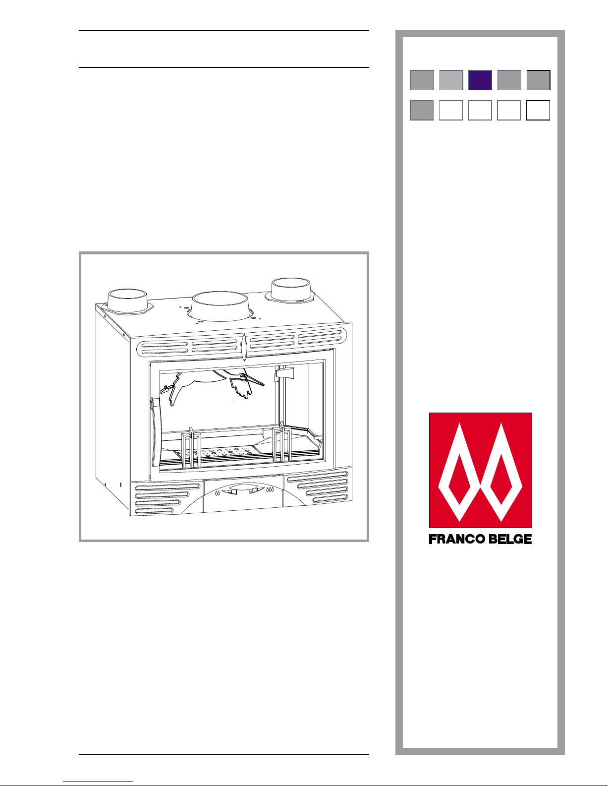
Hekla
Insert fire
IGBsfIn-NFD35-376
Model : 634 10 44
Model : 634 10 45
ES EN NL PL IT
FR IT EN NL PT
Technical manual
to be saved
by the user
for future reference

2 Technical manual “1204”
“Hekla” - ref. 634 10 44/634 10 45
CONTENTS
Description of the unit ...................................p.3
Specifications . . . . . . . . . . . . . . . p. 3
Optional equipment. . . . . . . . . . . . p. 3
Description . . . . . . . . . . . . . . . . p. 4
Working principle . . . . . . . . . . . . . p. 4
Installation instructions...................................p.5
The room . . . . . . . . . . . . . . . . . p. 5
Flue . . . . . . . . . . . . . . . . . . . . p. 5
Connection to flue . . . . . . . . . . . . p. 5
Chimney built around the hearth . . . . p. 6
Insertion inside an existing chimney . . p. 6
Electrical connection . . . . . . . . . . . p. 8
Hot air outlets . . . . . . . . . . . . . . . p. 8
Flue baffle mounting . . . . . . . . . . . p. 9
Access to the fans . . . . . . . . . . . . p. 9
Maintenance of the chimney . . . . . . . p. 9
User instructions ......................................p.10
Fuel . . . . . . . . . . . . . . . . . . . p. 10
Lighting . . . . . . . . . . . . . . . . . p. 10
Air convection principle . . . . . . . . . p. 10
Combustion . . . . . . . . . . . . . . . p. 10
De-ashing . . . . . . . . . . . . . . . . p. 11
Recommendations . . . . . . . . . . . p. 11
Cleaning of the insert fire. . . . . . . . p. 11
Trouble shooting . . . . . . . . . . . . p. 11
Spare parts .........................................p.12
FRANCO BELGE congratulates you on your choice.
FRANCO BELGE, which has been granted the ISO 9001 certification, guarantees the quality of its
appliances and is committed to meet its customers’ needs.
FRANCO BELGE, which can boast a 75-year experience in the industry of heating devices, uses
state-of-the-art technologies
to design and manufacture its whole range of products.
This document contains instructions on how to install your appliance and make full use of its
functions, both for your comfort and safety.
Warning to the user
A wood stove should only be installed by competent personnel, in the strict application of
normal practices and all safety precautions.
An incorrectly installed wood stove can cause serious accidents (chimney fires, burning of
plastic insulation materials, in partition walls, etc.).
The manufacturer’s responsibility shall be limited to the supply of the equipment.
1. Description of the unit
1.1.
Specifications
Model .....................................6341044 ......6341045
Normal heat output ....................kW..........10...........10
Firebox dimensions
width x depth x height .................. mm.......585x325x350.....585x325x350
Logs dimensions :
- length...........................cm..........50...........50
- diameter .........................cm........10to16 .......10to16
Ash pan capacity ....................liters .........2,5..........2,5
Weight ...........................kg.........115..........115
Autonomy at minimum rate ................hr..........7...........7
Corrected heating volume.................m
3
.........400..........400
Firebox draught at maximum rate ............Pa..........10...........10
Firebox draught at minimum rate .............Pa..........5 ...........5
Fans
- voltage (~ 50 Hz) .....................V.........230...........-
- Electrical power consumed................W.........2x35..........-
1.2. Optional equipment
-
Kit variator of speed for the ventilation
-
Kit handle brassplated (KP 1013 D) or chrome (KP 1013 N)
Technical manual “1204” 3
“Hekla” - ref. 634 10 44/634 10 45 Description of the unit
581
333
541
730
703 *
571 *
537
464 *
213
82
619
O.D.
O.D.
Ø180
ext.
Ø125
ext.
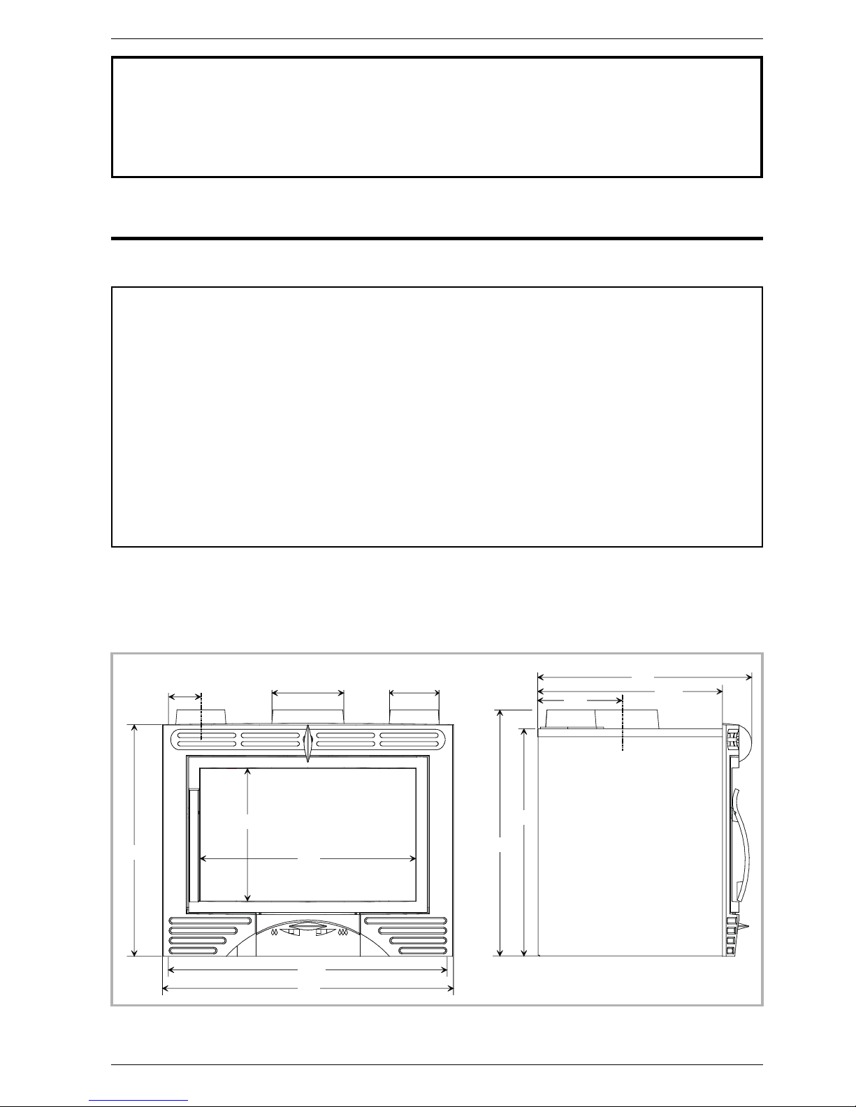
Figure 1 - Dimensions in mm
* Part to insert
1.3. Description
Insert fire,IGBsfIn-NFD35-375
I : Intermittent-burning heating appliance.
G : Wood burnt on grate
B : Wood burning
sf : semi-close cast iron firebox with a decorated
hearth plate and fire dogs.
In : Insert fire
•
Hot air convector made of double stainless steel walls
forming the heat exchanger.
•
(model 634 10 44 only) Two fans with automatic start to
accelerate the hot air convection.
•
A door made of “vitroceramic” glass which can resist to
temperatures of up to 750° C and also acts as a sparks
guard.
•
Combustion speed regulated with an air flap situated
on the main door.
•
Draught flue damper with a frontal control.
1.4. Working principle
The insert is made to fit into an existing chimney. It can
also be used as the hearth of a chimney about to be
built.
Strong heat will come through the glass door by
radiation.
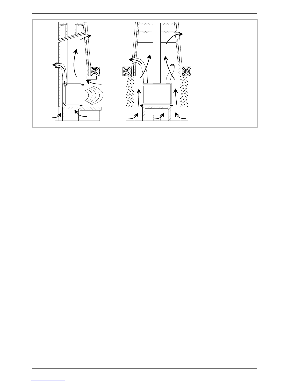
The air is collected at the bottom of the appliance
around the ash pan, spreads around the fire where it
becomes hot and is passed out at the top of the unit to
convect its efficiently heated air around the room.
(model 634 10 44 only) The air leaving the heat
exchanger is accelereted by the automatic start of the
fans when the hot air temperature is more than 50 °C.
The fans stop when the air temperature fall down.
The speed is regulated with the primary air flap situated
on the main door.
A clever secondary air inlet around the glass door
completes the combustion of volatile components and
allows the door to remain clean.
The flue damper allows and even combustion speed
depending on the chimney draught.
4 Technical manual “1204”
“Hekla” - ref. 634 10 44/634 10 45 Description of the unit
1
1
2
2
2
2
2
2
1
1
2
1
3
Figure 2 - Heating principle
1 - Hot air diffusion
2 - Ambiant air
3 - Radiation
2. Installation instructions
2.1. The room
Ventilation :
For satisfactory operation with a natural draught, check
that sufficient air for combustion is available in the
room.
Chimney position :
For new chimney installations, select a central position
within the building, to provide a good heat distribution
around the building.
Hearth :
The hearth must be suitable for use with solid fuel
burning appliances and must comply with Current
Building Regulations. If in doubt, consult your Dealer or
local Building Inspector.
Rear wall and ceiling :
The appliance must not be positioned close to
combustible materials, wall & ceiling surfaces etc..,
Consult your Dealer or local Building Inspector if in
doubt.
2.2. Flue
Existing flue :
-
The flue must be in good condition and must provide
sufficient draught.
-
The flue must be suitable for the installation of solid
fuel burning appliances and comply with Current
Building Regulations.
-
The flue must be clean. It should be swept to remove
soot and dislodge tar deposits.
-
The flue must be well insulated. If the flue inner wall
surfaces are cold, a good thermal draw is impossible
causing condensation problems (tar formation etc).
-
The flue must not be shared with other appliances.
-
The recommended minimum flue height is 5 metres.
-
If the chimney has any down draught tendency, due to
its position in relation to nearby obstacles, an
anti-down draught cowl must be installed on the
chimney or the chimney height must be increased.
-
If the decompression in the chimney is excessive, a
draught stabiliser must be installed.
Chimney to be built / Flue non-existent :
-
The stove must not support the weight of the flue.
-
Consult a chimney specialist for advice on suitable
flue systems for solid fuel appliances.
2.3. Connection to flue
-
The stove must be installed as close as possible to the
chimney.
-
The stove should be connected to the flue by a smoke
pipe, approved for installation with combustion
products (e.g. 360 stainless steel 1 mm thick or
vitreous enamel.).
-
Pipe diameter must not be less than the appliance
spigot diameter.
-
The connection can be either vertical or horizontal. For
horizontal connections, avoid right angle bends.
-
The join between the connection pipe and the
stovepipe, and the flue, must be leak tight.
-
The connection pipe and any draught stabiliser must
have access for cleaning
Technical manual “1204” 5
“Hekla” - ref. 634 10 44/634 10 45 Installation instructions
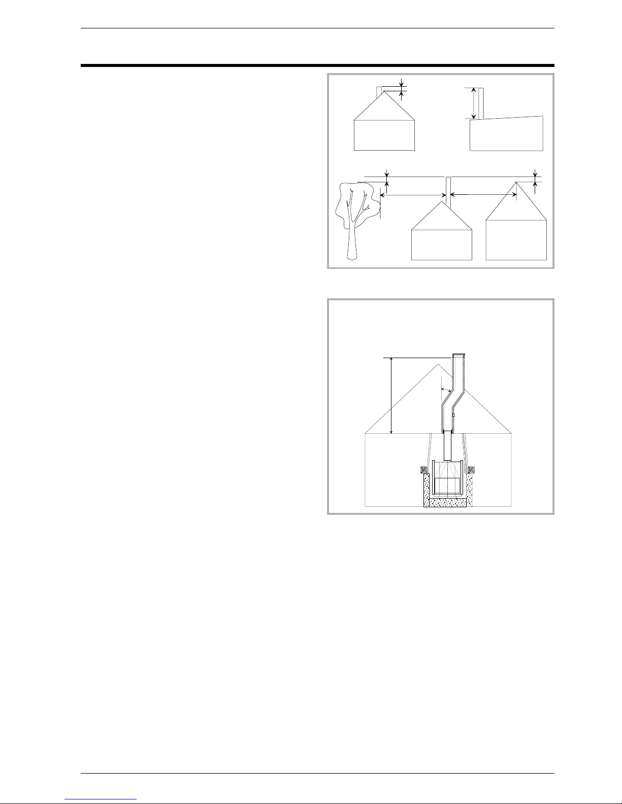
4 0 c m
8 m
4 0 c m
4 0 c m
8 m
1 , 2 m
p e n t e < 1 5 °
Figure 3 - Flue upper section height
H
=
=
=
< 4 5 ° s i H < 5 m
2 0 ° <
< 2 0 °
Figure 4 - Flue offset
 Loading...