

FRANCO BELGE Burgundy 174 10 25, Burgundy 174 10 31 Technical Manual
Technicalmanual
tobesaved
bytheuser
forfuturereference
Documentn°809-5EN~15/04/1999
LesFonderiesFranco-Belges
59660MERVILLE
Phone:03.28.43.43.43
Fax:03.28.43.43.99
RCHazebrouck445750565B
Subjecttomodifications
Burgundy
Oilburningstove
1741025
1741031
EN1-NFD35-385
Françaisp.1-12
Englishp.13-24
Descriptionoftheappliance
Installationinstructions
Operatinginstructions
Spareparts
Warrantycertificate
Nederlandsbl.25-36

Descriptionoftheunit...................15
Package.............................15
Specifications..........................15
Description...........................15
Installationinstructions..................16
Positionoftheunit.......................16
Chimney.............................16
Chimneyconnector.......................16
Levelling ............................16
Mountingthetray........................16
Fittingofthehandle......................16
Fittingthe“visioflamme”....................16
Externaltank..........................17
Oilflowadjustment.......................17
Chimneydraught........................18
MaintenanceoftheChimney.................18
Operatinginstructions...................19
Fuel...............................19
Lightingprocedure.......................19
Operatingprocedure......................19
Shuttingdown.........................19
Recommendation........................19
Maintenanceofthestove...................19
Troubleshooting........................20
Spareparts.........................21
Page
CONTENTS
Documentn°809-5EN~15/04/1999
Burgundy Oilburningstove
14 Technicalmanual

1.Descriptionoftheunit
1.1.Package
-1package:Stovecomplete
-1package:Groundvatandmirrors
1.2.Specifications
NominalHeatOutput(NFD35-385)
........................kW 10
......................Btu/hr 34,130
Oilconsumptionat:...............
-maximumspeed.............litre/h 1,25
....................Impgal/hr 0.275
....................USgal/hr 0.33
-minimumspeed.............litre/h 0,25
....................Impgal/hr 0.055
....................USgal/hr 0.066
Chimneydraftrequiredat:...........
-maximumspeed..............Pa 20
......................in.w.g. 0.0802
-minimumspeed..............Pa 6
......................in.w.g. 0.024
Weight....................kg 118
........................lbs 260
Flueoutletdiameter(O/D).........mm 120/125
.........................in 5
1.3.Description
Fluedoilstovewithvaporizingburner(NormEN1)
Ø120/125mm
(5")
620mm(241/2")
402mm(16")
544mm(211/2")
505mm
(20")
678mm
(27")
383mm(15")
Ill.1-Dimensionsinmm
SAFETYNOTICE:Readcarefullyallinstru ction s
beforestartingtheinstallation.Ifthestoveisnot
properlyinstalled,ahousefiremayresult.Foryour
safety,followtheinstallationdirections.Contactlocal
buildingorfireofficialsaboutr estrictionsand
installationinspectioninyourarea.
Documentn°809-5EN~15/04/1999
Oilburningstove Burgundy
Technicalmanual 15
2.Installationinstructions
2.1.Positionoftheunit
-Thepositionoftheappliancemustbechosenverycarefullyinordertoobtainthebestpossibleresultsforheat
distribution.
-Positiontheunittocomplywiththeminimumclearances
tocombustiblematerial.Minimumclearancesareshown
fromtheverticalportionofthechimneyconnector.Check
thatnooverheadcrossmembersintheceilingwillbecut.
Repositionunitifnecessary,beingcarefulnottomove
closerthantheminimumclearances.
2.2.Chimney
-Ensurethatthefluehassufficientdraught(refertotechnicaldetails).
-Minimumfluediameter,10cm(4"I.D).
-Thechimneymustbeatleast4.5m(15fthigh).
-Thefluemustnotbesharedwithanyotherappliance.
-Downdraughtscausedbyobstaclesclosetothechimney
topmaysometimesbepreventedbyfittingananti-downdraughtcaptothetopofthechimney.
-Thechimneymusthaveaconstantcrosssection.Too
largeafluecouldaffectthechimneydraught.
-Thechimneymustbesoundlyconstructed,inorderto
preventcoldairinfiltration.
-Thefluemustbewellinsulated,waterandairtight.A
chimneywithacoldinternalsurfacecanpreventagood
chimneydraughtandcondensationwilloccur.
-Thefluemustbesweptatleastonceayear.
2.3.Chimneyconnector
-Theappliancemustbeascloseaspossibletothechimney.Avoidhorizontalflueconnectionpipeswhichcan
dangerouslyrestrainfunctioningoftheappliance.
-Theconnectorpipeshouldbestandardblackpaintedor
bluedsteelpipeofnotlessthan30gage;304grade
stainlesssteelofnotlessthan30gage;or1mmviterous
enamelledsteel,withamaximumdiameterof5inchO.D.
-(127mm).Itistheinstaller’sresponsabilitytoconformto
localbuildingstandardsandrequirementswithregardto
installation..Singlewallpipemaybeutilizedbeingcareful
tomaintainclearancestoanycombustiblesurface.
Oncethestovehasbeenproperlyinstalledthechimney
draughtmustbecheckedwithadraughtmeter.
Ifthechimneydraughtisexcessiveorirregular,adraught
stabilizer(barometricdamper)mustbeinstalledtothe
connectorpipe.
2.4.Levelling
Figure3and4
Itisessentialthattheappliancesitslevelonthefloor.Fit
the4screwsandthe4capssupplied(ontheburner)on
thefeet.Useaspiritleveltocheck.
2.5.Mountingthetray
Figure6
Toavoiddamagetotheashtrayduringtransport,ithas
beendisconnectedandstoredbehindthemaindoorofthe
oilstove.Toreinstalltheashtraytothefrontoftheoil
stove,tiltthetrayata45°angle,centerontotab‘A’and
lowerintoplace.
2.6.Fittingofthehandle
Figure5
Inordertoavoidthedamagingofthethreading,firstput
thehandleinoperatingpositionthenscrewitintothe
tapingofthelock.
2.7.Fittingthe“visioflamme”
Fittheglasses(#59,p.22)ontothereflector(#28,p.22).
7
2
3
4
5
6
9
8
10
1
11
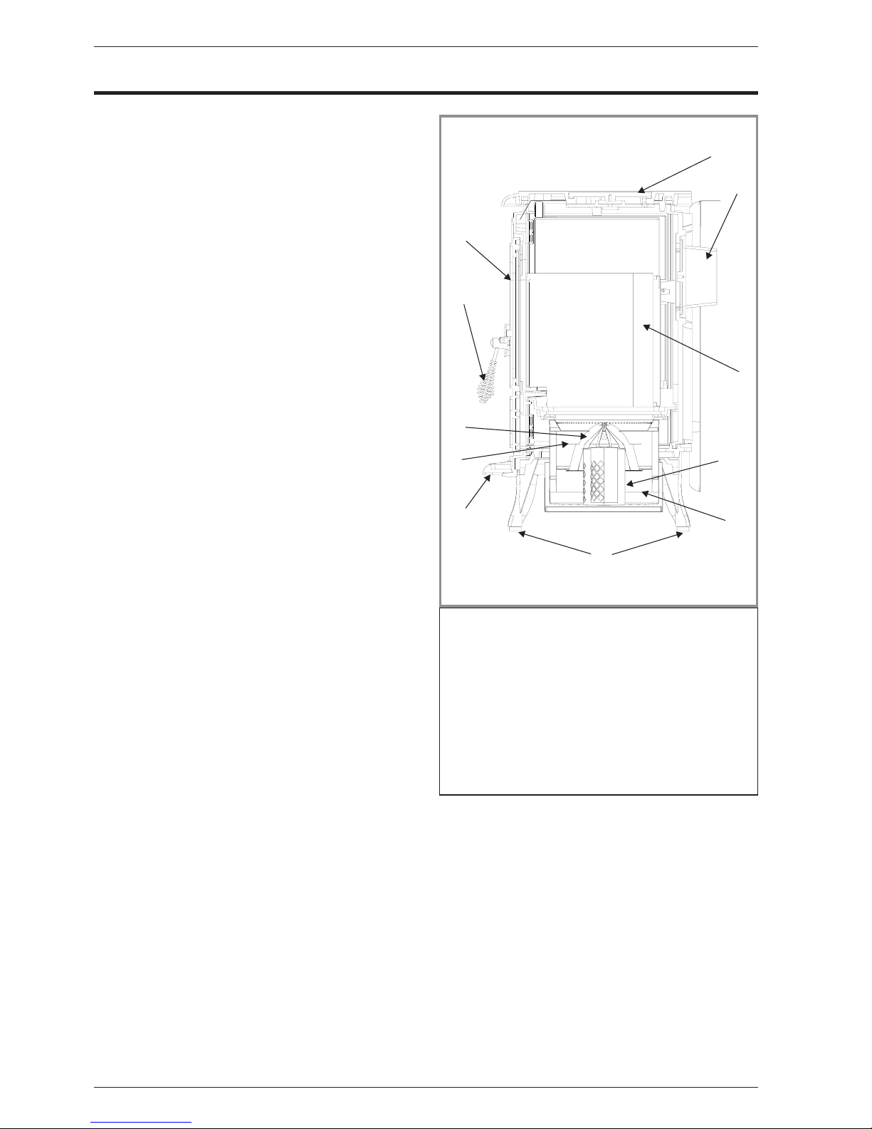
Ill.2-Cross section
1-Blankingplate
(notprovidedtobe
connectedtothe
chimney).
2-Maindoor.
3-Openingandclosing
ofthelowerdoor.
4-Catalysertop.
5-Upperring.
6-Catalyser.
7-Fluecollar.
8-Reflector.
9-Burner.
10-Tray
11-Screws
Documentn°809-5EN~15/04/1999
Burgundy Oilburningstove
16 Technicalmanual
 Loading...