

FRANCO BELGE Bourgogne Technical Manual
Description of the appliance
Installation instructions
Operating instructions
Spare parts
Warranty certificate
Document n° 1091-6 ~ 25/10/2005
Bourgogne
Oil burning stove
Ref. 174 10 56
(NF EN 1)
Technical manual
to be saved
by the user
for future reference
STAUB FONDERIE
SARL with the capital of 6 359 540 &
Head Office Address
2, rue Saint Gilles
68230 TURCKHEIM
RCS Colmar
SIREN 444 881 953
Address
Administration and manufacturing
BP 73
59660 MERVILLE (FRANCE)
Telephone : 00 333 28 43 43 00
Fax : 00 333 28 43 43 99
Subject to modifications.
2 Technical manual “1091”
“Bourgogne” ref. : 174 10 56
CONTENTS
Description of the unit ...................................P.3
Description ................P.3
Package..................P.3
Optional equipment ...........P.3
Specifications. . . . . . . . . . . . . . . P. 3
Operating principle . . . . . . . . . . . . P. 4
Installation instructions...................................P.5
Warning to the user ...........P.5
Location of the unit............P.5
Chimney .................P.5
Smoke exit ................P.6
Chimney connector............P.6
Levelling .................P.6
External / remote tank ..........P.6
Pre-utilization check . . . . . . . . . . . P. 7
Oil flows adjustment . . . . . . . . . . . P. 7
Mounting the tray. . . . . . . . . . . . . P. 8
Chimney draught . . . . . . . . . . . . . P. 8
Maintenance of the Chimney . . . . . . P. 8
Fitting the “visioflamme” (optional) . . . P. 8
Instructions for user.....................................P.9
Fuel ....................P.9
Lighting ..................P.9
Operating procedure ...........P.9
Shutting down ..............P.9
Recommendations . . . . . . . . . . . P. 10
Maintenance of the stove. . . . . . . . P. 10
Removing the burner . . . . . . . . . . P. 10
Trouble shooting . . . . . . . . . . . . P. 11
Spare parts .........................................P.12
FRANCO BELGE congratulates you on your choice.
FRANCO BELGE, which has been granted the ISO 9001 certification, guarantees the
quality of its appliances and is committed to meet its customers’ needs.
FRANCO BELGE, which can boast a 75-year experience in the industry of heating devices,
uses state-of-the-art technologies
to design and manufacture its whole range of products.
This document contains instructions on how to install your appliance and make full use of
its functions, both for your comfort and safety.
This appliance is an oil-fired stove.
WARNING
An incorrectly installed oil-fired stove can cause serious accidents.
This appliance should only be installed by competent personnel.
1. Description of the unit
1.1. Description
Flued oil stove with vaporizing burner. (Norm EN1)
1.2. Package
•
1 package : Stove
1.3. Optional equipment
•
1 package : Visioflamme (mirrors : P 174 10 53)
•
1 package : Glow-plug ignitor
•
1 package : Coals kit (FC 0802)
1.4. Specifications
Model ................. 1741056
Nominal Heat Output .......kW 10
Oil consumption
at maximum speed .......litre/hr 1,27
at minimum speed .......litre/hr 0,25
Chimney draft required
at maximum speed .........Pa 17
at minimum speed .........Pa 8
Weight ................kg 118
Technical manual “1091” 3
“Bourgogne” ref. : 174 10 56 Description of the unit
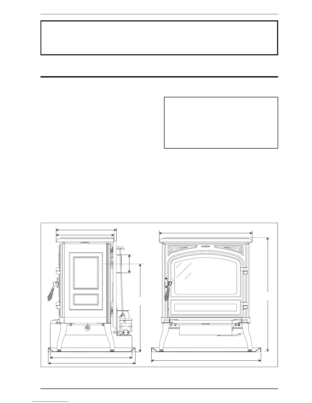
5 4 4
5 8 5
Ø 1 2 0 / 1 2 5
3 8 5
4 0 2
6 2 0
7 6 0
5 6 2
7 0 2
Figure 1 - Dimensions in mm
1.5. Operating principle
Heat is mainly diffused by radiation, through the window
and body of the appliance.
The speed control is obtained by control the oil flow into
the burner.
The stove is fitted with a vaporizing burner
Furnace oil is fed to the burner floor where is it ignited
by means of a firestarter (or with an optional electrical
igniter).
The heat produced by this flame brings the burner
temperature to the required level to vaporize the oil.
Oil will only burn as a vapor not a liquid.
Combustive air enters the burner through the air way
holes.
In the centre of the burner is the catalyser, which aids
the good combustion.
When the stove is in operation, the catalyser glows red.
The stove should not be used without the catalyser.
On the feed-line there is a de-scaling lever.
The de-scaling lever can be operated to keep the inlet
pipe clear of carbon build-up.
The stove float regulator contains a filter to trap
impurities. A safety lever controls oil flow. A float in the
chamber raises the oil level available to the burner.
Oil can only enter the float chamber when the safety
lever is depressed.
The float regulator is also controlled by a control knob
which turns from off to high setting.
A draft regulator ensures a constant air intake to the
burner regardless of external factors.
4 Technical manual “1091”
“Bourgogne” ref. : 174 10 56 Description of the unit
1
2
2 b
2 c
3
4
5
2 a
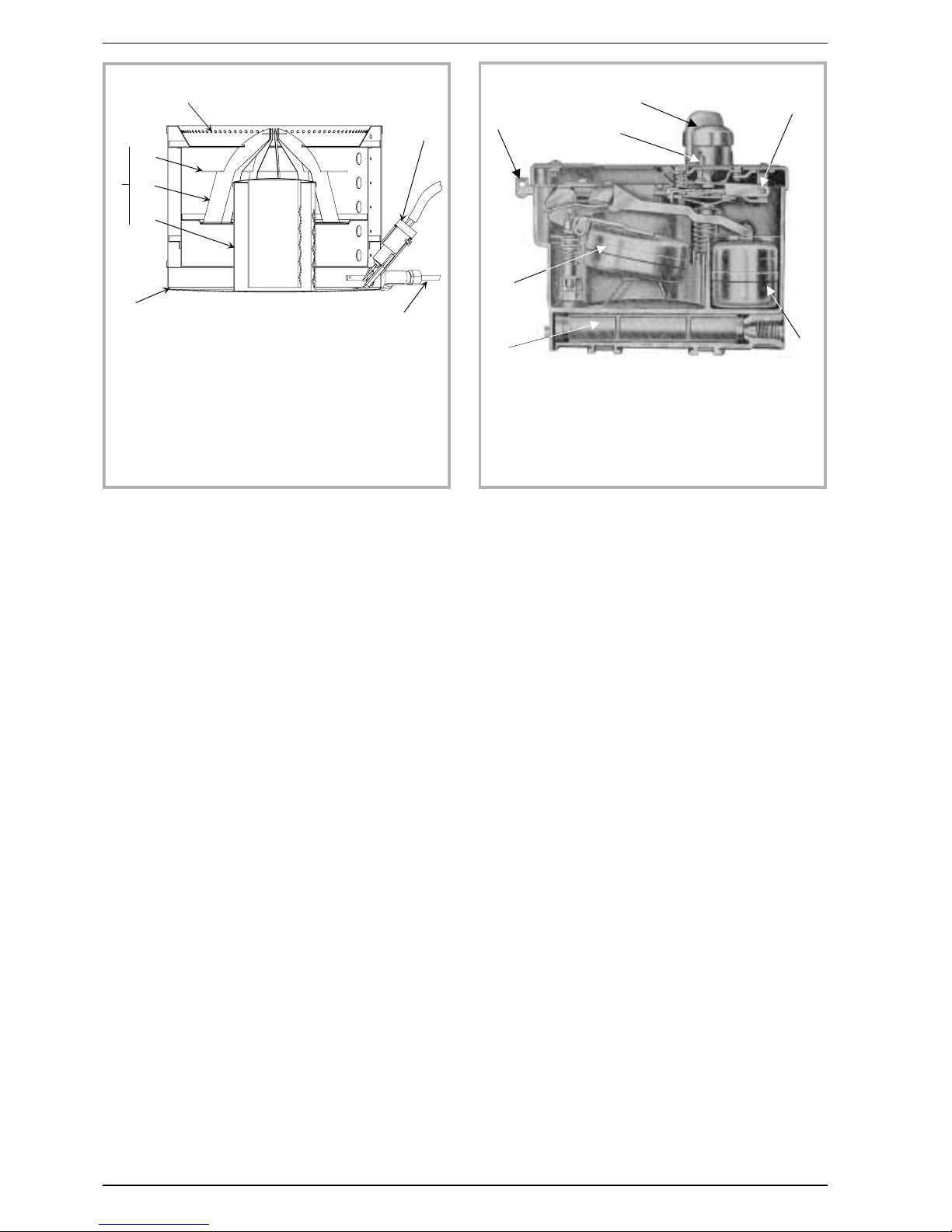
Figure 2 - Burner
1 - Air holes
2 - Catalyser
2a : Upper ring
2b : Catalyser top
2c : Catalyser body
3 - Burner pot
4 - Automatic ignition
(optional)
5 - De-scaling lever
Figure 3 - Float regulator
A - Control knob
B - Safety lever.
C - Main float
D - Safety float
E - Oil level regulator
F - Thermostat control
G - Filter
A
F
B
E
G
C
D
2. Installation instructions
2.1. Warning to the user
An incorrectly installed heating appliance can
cause serious accidents (chimney fires, burning of
plastic insulation materials, in partition walls, etc.).
The insulation of both the appliance and the
exhaust gas pipe has to be reinforced and built as
well as possible according to the norm to make sure of
the equipment operational reliability.
The installation must be carried out according to local
building regulations.
It is the installer’s responsibility to conform to local
building standards and requirements with regard to
installation.
The manufacturer’s responsibility shall be limited to the
supply of the equipment.
A remote acting fire valve must be fitted on the oil
supply line.
Flexible oil lines must not be used to make connections
between oil supply line and oil regulator valve.
2.2. Location of the unit
Ventilation :
For satisfactory operation with a natural draught,
check that sufficient air for combustion is available in
the room.
In houses equipped with mechanical ventilation, an
outside air intake of minimum 50 cm
2
must be installed.
Position of the unit :
For new installations, select a central position within the
house, to provide a good heat distribution around the
building.
The heat distribution towards the other rooms will be
made through the communicating doors. These rooms
must be in negative pressure or must include ventilation
gratings.
Floor and walls :
Make sure there are not combustible or covered with
combustible material.
Otherwise it must be necessary to install a
non-combustible protection.
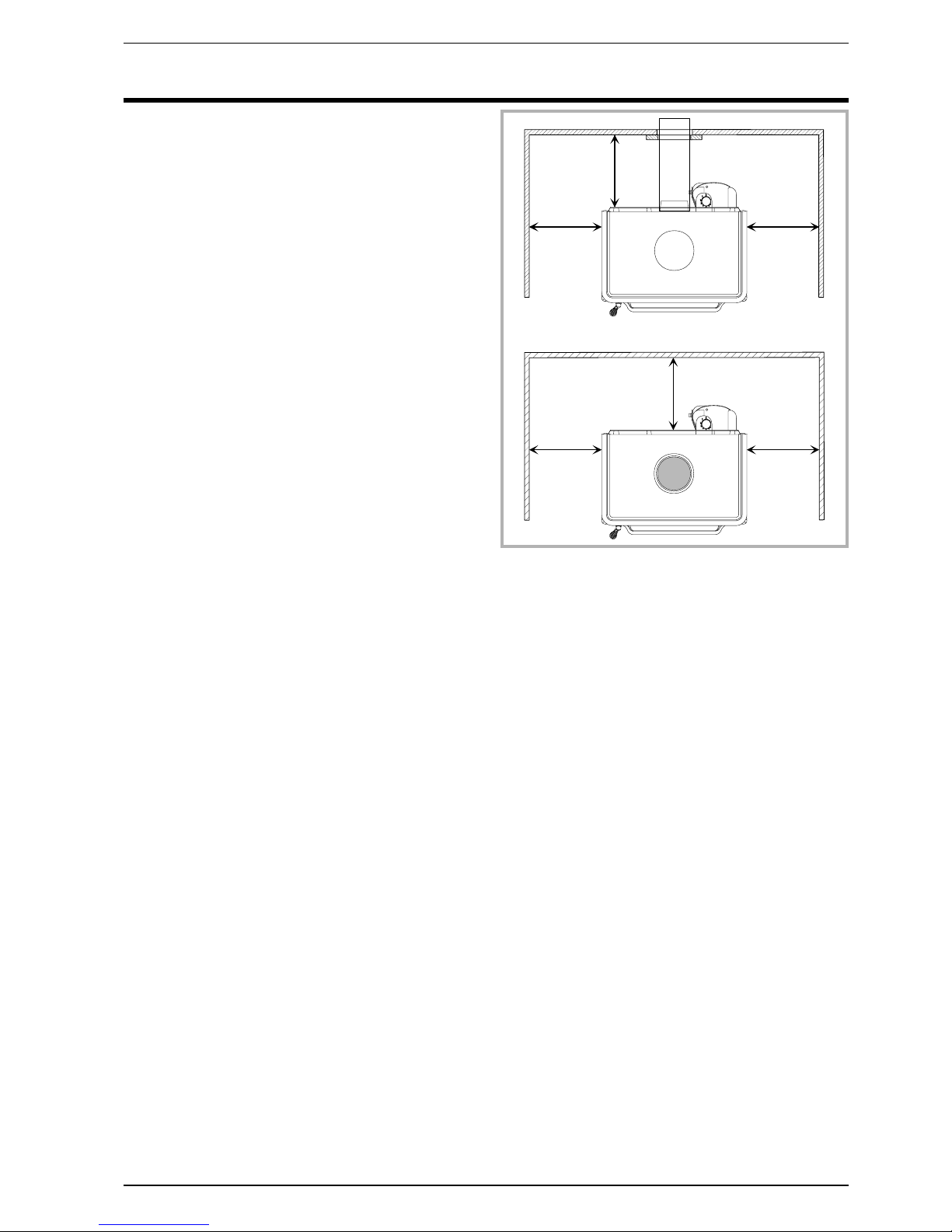
Position the unit to comply with the minimum
clearances to combustible material (figure 4).
2.3. Chimney
The chimney must comply with Current Building
Regulations. If in doubt, consult your Dealer or local
Building Inspector.
The flue must be in good condition and must provide
sufficient draught. (refer to technical details page 3).
The flue must be suitable for the installation of fuel
burning appliances ; otherwise it must necessary to
install a tubing.
The flue must be clean. It should be swept to remove
soot and dislodge tar deposits.
The flue must be well insulated, water and air tight. A
chimney with a cold internal surface can prevent a good
chimney draught and condensation will occur.
The flue must be watertight.
The chimney must have a constant cross section.
The flue must not be shared with any other appliance.
The chimney must be at least 4.5 m (15 ft) high.
In case of a flat roof or when the roof gradient is lower
than 15°, the stack must be 1,2 m (4 feet) high at least.
The capping must not restrain the draught.
If the chimney has any downdraught tendency, due to
its position in relation to nearby obstacles, an
anti-downdraught cowl must be installed on the
chimney or the chimney height must be increased.
If the chimney draught is excessive or irregular, a
draught stabilizer (barometric damper) must be
installed to the connector pipe.
It must be distant from any combustible material (walls,
cross members)
It must permit an easy sweeping.
Technical manual “1091” 5
“Bourgogne” ref. : 174 10 56 Installation instructions
3 0 0
3 0 0
3 0 0
3 0 0
3 0 0
3 0 0
Figure 4 - Minimum clearances
 Loading...