

FRANCO BELGE Belfort 174 05 05 Technical Manual
Technical manual
to be saved
by th e user
for future reference
Document n° 979-3 EN ~ 28/02/2000
Les FonderiesFranco-B el ges
59660 MERVILLE
Phone : 03.28.43.43.43
Fax : 03.28.43.43.99
RC Hazebrouck 445750565B
Subject to modifications
Belfort
Oil fir ed stove
Model : 174 05 05
(EN 1)
Description of the a pplian ce
Installation instructions
Operating instructions
Spare par ts
English
Norsk

Description of the unit ........................................3
Package....................3
Optional equipment ..............3
Specifications.................3
Description ..................3
Operatingprinciple..............4
Installationinstructions .......................................4
Positionoftheunit ..............4
Chimney....................4
Mounting the levelling feet ..........5
Topflueoutlet.................5
Rearflueoutlet ................5
Chimney connector ..............5
Externaltank .................6
Levelling ....................6
Pre-utilisation check .............6
Oilflowadjustment ..............6
Chimney draught ...............7
Doorclosingpressure ............7
MaintenanceoftheChimney.........7
Operatinginstructions ........................................8
Fuel ......................8
Lighting procedure ..............8
Operating procedure .............8
Shuttingdown.................8
Maintenanceofthestove...........8
Recommendation ...............9
Trouble shooting .............. 10
Spareparts..............................................11
FRANCO BELGE congratulates you on your choice.
FRANCO BELGE, which has been granted the ISO 90 01 certification, guarantees the quality of its
appliances and is committed to meet its customers’ needs.
FRANCO BELGE, which can boast a 75-year experience in the industry of heating devices, uses
state-of-the-art technologies to design and manufacture its whole range of products.
This document contains instructions on how to install your appliance and and make full use of its
functions, both for your comfort and safety.
CONTENTS Page Page
Document n° 979-3 EN ~28/02/2000
174 05 05 BELFORT Oil fired stove
2 Technical manual
1.Description of the unit
1.1. Package
¤ 1 package. The stove is supplied completely
assembled exceptthe four levelling feet that areplaced
on the burner.
1.2.Optional equipment
¤ Ground vat
¤ Glow-plug ignitor
1.3.
Specifications
Model ...................... 1740505
Nominal heat output . . . . . . . . . . . . kW 5
. . . . . . . . . . . . . . . . . . . . . . BTU/hr 18.000
Oil consumption at :
-maximumspeed ............litre/h 0,58
.......................gal/hr 0,16
- minimum speed . . . . . . . . . . . . . litre/h 0,17
.......................gal/hr 0,045
Chimney draugh t required at :
-maximumspeed ............. Pa 15
-minimumspeed.............. Pa 8
Weight .................... kg 67,6
1.4.Description
Flued oil stove with vaporizing burner
(Norm EN 1).
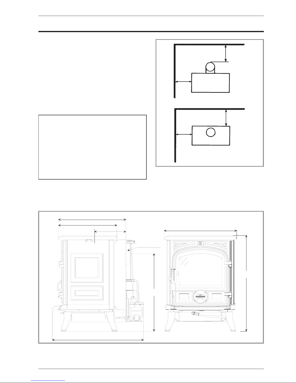
Figure 1 - Minimum clearances to combustible walls
392
340
182
Ø 120/127
452
530
558
420
Figure 2 - Dimensions in mm
200 mm
200
mm
200 mm
200
mm
Document n° 979-3 EN ~28/02/2000
Oil fired stove BELFORT 174 05 05
Technical manual 3
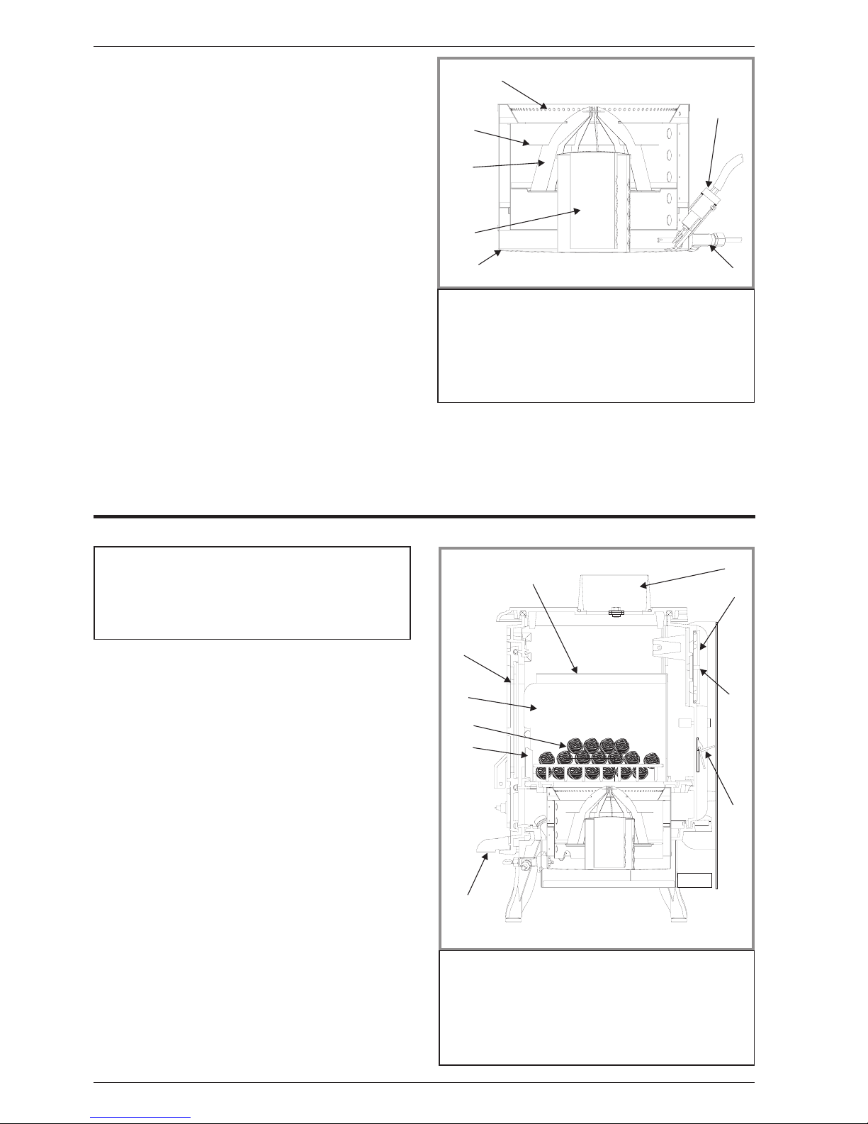
1.5. Operating principle
Furnace oil is fed to the burner floor (fig. 3) where is it
ignited by means of a firestarter (or the Glow-plug
ignitor # 6). The heat produced by this flame brings the
burner temperatureto the required level to vaporize the
fuel. Oil will only burn as a vapour not a liquid.
Room combustion air enters the burner through the air
inlet holes.
In the center of the burner is the catalyser (# 4, fig. 3)
which aids in vaporizing the fuel. When the stove is
operation,thecatalyserglowsred.The stove should not
be used with out both the catalyser (# 4, fig. 3),
catalyser top (# 3) and ring (# 2).
A de-scaling lever (#7, fig.3) can be pushed andpulled
in and out as well as turning slightly at the sametime to
keep the inlet pipe clear of carbon buildup.
The stove float regulator contains a filter to trap
impurities.
A safety lever controls fuel flow. Oil can only enter the
float chamber when the safety lever is depressed.
Oil temperature variations will affect the oil flow into the
float chamber. A float in the chamber raises the fuel
level available to the burner.
The float regulator is also controlled by a control knob
which turns from “0" (off) to ”6" (high setting).
A draught regulator (# 1, fig. 12, p. 6) ensures a
constant air int ake to the burner regardless of external
factors.
2.Installation instructions
SAFETY NOTICE : Read carefullyall instructions before
starting the installation. If thestove is not properly installed, a house fire may result. For your safety, follow the
installation directions. Contact local building or fire officials about restrictions and installation inspection in your
area.
2.1.Position of the unit
- The position of the appliance must be chosen very
carefully in order to obtain the best possible results for
heat distr ibution .
- Position the unit to comply with the minimum
clearances to combustible material. M inimum
clearances are shown from the vertical port ion of the
chimney connector. Check that no overhead cross
members in the ceiling will be cut. Reposition unit if
necessary , being careful not to move closer than the
minimum clearances.
- Outside air : For the oil stove to function properly, an
adequate supply of combustion air is required.
2.2. Chimney
- Ensure that the flue has sufficient draught (refer to
technical details).
- Minimum flue diameter, 10 cm (4" I.D).
- The chimney must be at least 4.5 m (15 ft high).
- The flue must not be shared with anyother appliance.
- Downdraughts caused by obstacles close to the
chimney top may sometimes be prevented by fitting an
anti-downdraught cap to the top of the chimney.
- The chimney must have a constant cross section. T o o
large a flue could affect the chimney draught.
1
2
3
4
5
6
7
Figure 3 - Burner
1 - Air holes
2 - Upper ring
3 - Catalyser top
4 - Catalyser
5 - Burner
6 - Glow-plug ignitor
(optional)
7 - De-scaling lever
1
2
4
5
3
6
7
8
9
10
Figure 4 - Description
1 - Blanking plate
2 -Maindoor
3- Flue collar
4 - Baffle
5 -Tray
6- Sliding door
7 - Supplementary baffle
8 - Draught control
9 - Ceramic coal
10 - Coal support
Document n° 979-3 EN ~28/02/2000
174 05 05 BELFORT Oil fired stove
4 Technical manual
- The chimney must be soundly constructed, in order to
prevent cold air infiltration.
- The flue must be well insulated, water and air tight. A
chimney witha coldinternalsurfacecan prevent a good
chimney draught and condensation will occur.
- The flue must be swept at least once a year.
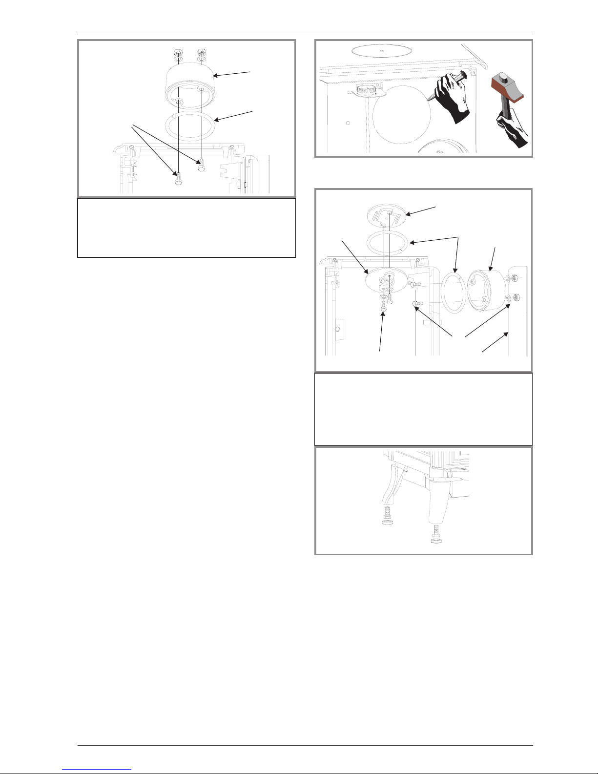
2.3.Mounting the levelling feet
Fitthe 4 screws and the 4 capssupplied (on the burner)
into each leg of the stove (fig. 8).
2.4.Top flue outlet
Figure 5
- Open the main door, remove the ceramic coal grate
with theirs coal (# 9 and 10,fig. 4, p. 4) and remove the
internalbaffle(#4and7,fig.4,p.4).
- Fix the sealingrope in the groove on the topand fit the
flue spigot using the two bolts and washers supplied,
ensuring there is a good seal.
- Replace the internal baffles.
The cut-out of the rearheat shieldmust not be remove
in the case.
2.5.Rear flue outlet
Figure 7
- Open the main door, remove the ceramic coal grate
with theirs coal (# 9 and 10, fig. 4, p. 4) and remove the
internalbaffle(#4and7,fig.4,p.4).
- Remove the rear heat shield and the cut-out on it
(fig. 6).
- Remove the blanking plate 5 and the clamp 4from the
back and refit them on the top with the 2 screws and
washers supplied 7, ensuring there is a good seal 2.
- Set the ceramic rope in the groove and fix the flue
collar at rear with 2 bolts and washers supplied.
- Reinstall the internal baffles.
- Replace the rear heat shield.
2.6. Chimney connector
- The appliance must be as close as possible to the
chimney. Avoid horizontal flue connection pipes which
can dangerously restrain functioning of the appliance.
- T he con nec tor pipe must be either 24 ga. black
painted or blued steel or 316 grade 20 ga. stainless
steelor1 mm vitreous enamelled steel, with a maximum
diameter of 127 mm (5" O.D.). Single wall pipe may be
utilized being careful to maintain clearances to any
combustible surface.
Once the stove hasbeen properly installed the chimney
draught must be checked with a draught meter.
If the chimney draught is excessive or irregular, a
3
1
2
Figure 5 - Top flue outlet
1 - Flue collar
2 - Sealing rope
3 - Screws, washers and
bolts
Figure 6 - Back panel
7
5
2
1
3
4
6
Figure 7 - Rear flue outlet
1 - Flue collar.
2 - Sealing rope.
3 - Back panel.
4 -Clamp.
5- B lanking plate.
6 - Screws, washers and
bolts.
7 - Screws and washers.
Figure 8 - Levelling
Document n° 979-3 EN ~28/02/2000
Oil fired stove BELFORT 174 05 05
Technical manual 5
draught stabilizer (barome tric damp er) must be
installed to the connector pipe.
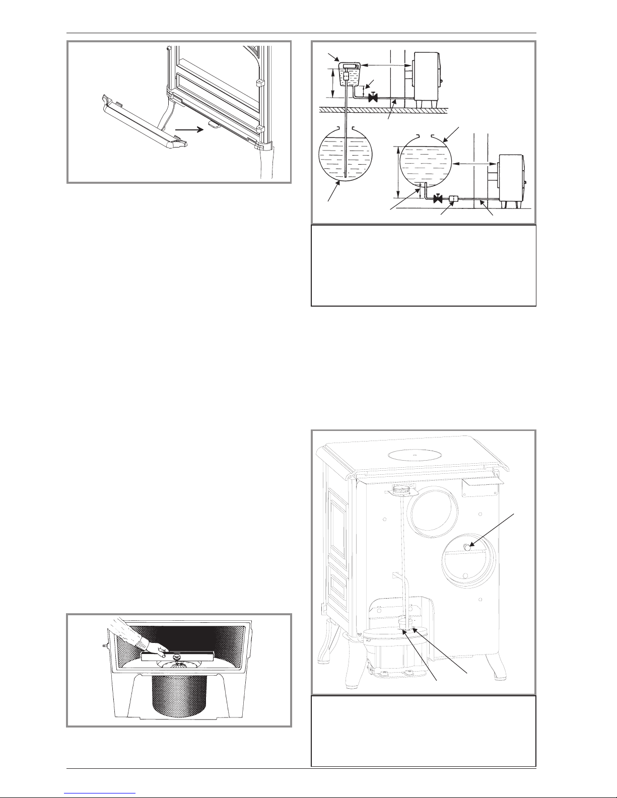
2.7.External tank
A barometric fuel tank should not be positioned where
it will be in the direct rays of the sun or adjacent to a
source of intense heat.
If the tank is more than 8 ft (2,5 m) higher than thestove a
pressure reducer must be installed on the oil line (max.
working pressure : 300 mbar).
If the tank islower than the stove a liftpump will have to be
utilized.
A clearance of 6“ (15 cm) must be maintained between
the external/remote tank and the stove.
2.8. Levelling
It is essential to ensure that the appliance sits level on
the floor. Adjust the levelling feet (fig. 8).
Use a spirit level across the burner pot to check the
level (fig. 10).
2.9. Pre-utilisation check
Check the condition of the filler seals, that the door
closes correctly, that the window is not damaged, that
the smoke passages are not obstructed by packaging
or removable parts. All removable parts, fuel retainer,
baffle, must be correctly installed.
2.10. Oil flow adjustment
The float regulator hasbeen adjusted at thefactoryand
should not need further adjustment. If the burner does
not work correctly, check possible causes before
readjusting the settings :
- Chimney draught
- Fresh air inlet
- Oil supply.
Low setting (Refer to # 2, fig. 12) :
- set the regulating knob on “1" and let the burner run
for a few minutes. The flamemust completely cover the
bottom of the burner and the catalyser body must be
glowing red hot.
- if the flame is too small, the stove will soot up quickly ;
increase the flame by turning the setting screw (# 2)
A
Figure 9 - Fitting the tray
Figure 10 - Burner level check
1
5
3
6
2
7
1
3
4
6
2
7
Figure 11 - Gravity or pumped oil supply
1 -2,5mmaxi
2- At least 0,25 m
3 - Oil Tank
4 - Filter
5 - Suction pump with
reserve and filter
6 - Pipe Ø 6x8 mm
7 - At least 0,15 m
1
2
3
Figure 12 - Adjustment devices
1 - Adjustment of the draught regulator
2 - Adjustment screw for low setting
3 - Adjustment screw for high setting
Document n° 979-3 EN ~28/02/2000
174 05 05 BELFORT Oil fired stove
6 Technical manual
clockwise.
- if the flameis too high, reducethe flameby turning the
setting screw (# 2) counter clockwise.
High setting (Refer to # 3, fig. 12) :
- set the regulating knob on “6" and let the burner run
fora few minutes. The flame must be shaped like a cone
and reach the upper part of the door.
- if the flame is too low, increase the flame by turning the
setting screw counter clock wise.
- if the flameis too high, reducethe flameby turning the
setting screw clockwise.
Please note - Very important : The adjustmentsof the
float regulator are very sensitive. The high and the low
setting screws mustnever be turned more thana 1/4 of
a turn at a time in any direction from theirinitial setting.
When making any adjustments, allow 3 to 5 minutes
between adjustments to allow burner to stabilize to
previous adjustment before proceeding, if necessary.
2.11. Chimney draught
Once the s tove has been properly installed, the
chimney draught must be checked.
The adjustment of the draught will be made with the
barometric damper located at the back of the stove
(# 1, fig. 12).
The reading of the draught must be done once the unit
is hot (minimum 30 minutes of use).
Refer to the specifications p. 3 for minimum draught
requirement on low setting and on high setting.
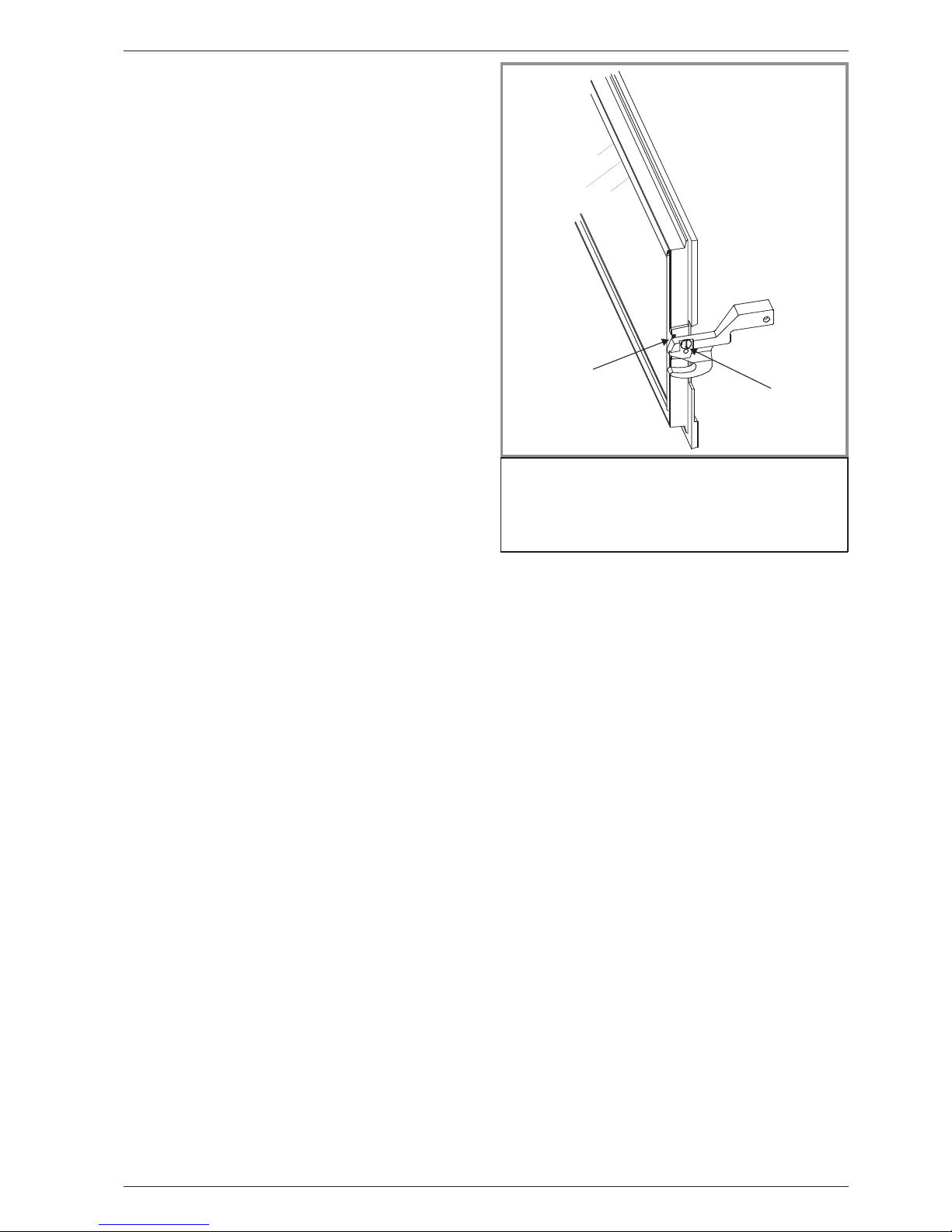
2.12. Door closing pressure
The closing latch rotates around a pressure screw
positioned cam (fig. 13).
- Loosen pressure screw 1.
- Turn cam to desired position 2.
- Tighten pressure screw 1.
2.13. Maintenance of the Chimney
Chimney and chimney connector should be inspected
at least once every three months during the heating
season to determine if a soot build up has occurred. If
soot has accumulated, it should be removed to reduce
the risk of a chimney fire.
1
2
Figure 13 - Door closing pressure
1 - Pressure screw
2 -Cam
Document n° 979-3 EN ~28/02/2000
Oil fired stove BELFORT 174 05 05
Technical manual 7
3.Operating instructions
3.1.Fuel
Warning
: Your stov e is fitted with a specific float
regulator for a specific oil.
¤ Kerosene 28 sec. (1,8 cst at 25°C)
The fuel oil must be free from any dirt and water which
could disturb the s tove in operation.
3.2.Lighting procedure
- Be sure the control knob is to “0" (# 1, fig. 14).
- Turn on oil supply,
- Push down gently on the safety lever (# 2, fig. 14).
This will allow the oil to flow into the float regulator.
- Open the front door, and remove the catalyser from
burner (# 2, 3 and 4, fig. 3, p. 4). Make sure the inside
of the pot is clea n thoroughly, and there is no oil
accumulation.
- Place 2 tablespoons of methylated spirit or gelled
alcohol in the bottom of the pot. Light the starter gel or
methylated spirit with a fireplace match or long butane
lighter. Place the catalyser back into the burner, being
sure it is centered in the burner. Shut the main door.
- Allow the catalyser to heatapproximately 30 to45 sec.
Turn dail to “1" position.
- Allow 10 to 15 minutes for oil fire and draught to
stabilize. The catalyse r should glow red before
adjusting the control knob to a higher setting.
3.3.Operating procedure
Allow 10 to 15 minutes after lighting to adjust the
control knob to a higher setting, usually between a “2"
and ”4" setting.
When increasing the heat output,movethecontrolknob
only 1 number at a time, allowing 5 minutes between
moves for the flame to re-adjust to new setting.
If the burner stops during operating, immediately turn
off the control knob (position “0") and wait until the
burner is completely cool before repeating the lighting
procedure.
3.4.Shutting down
- Set dial to the “0" position (# 1, fig. 14).
- R aise the safety lever of the float regulator
(# 2, fig. 14).
- Allow the flame to burn out completely before opening
the door.
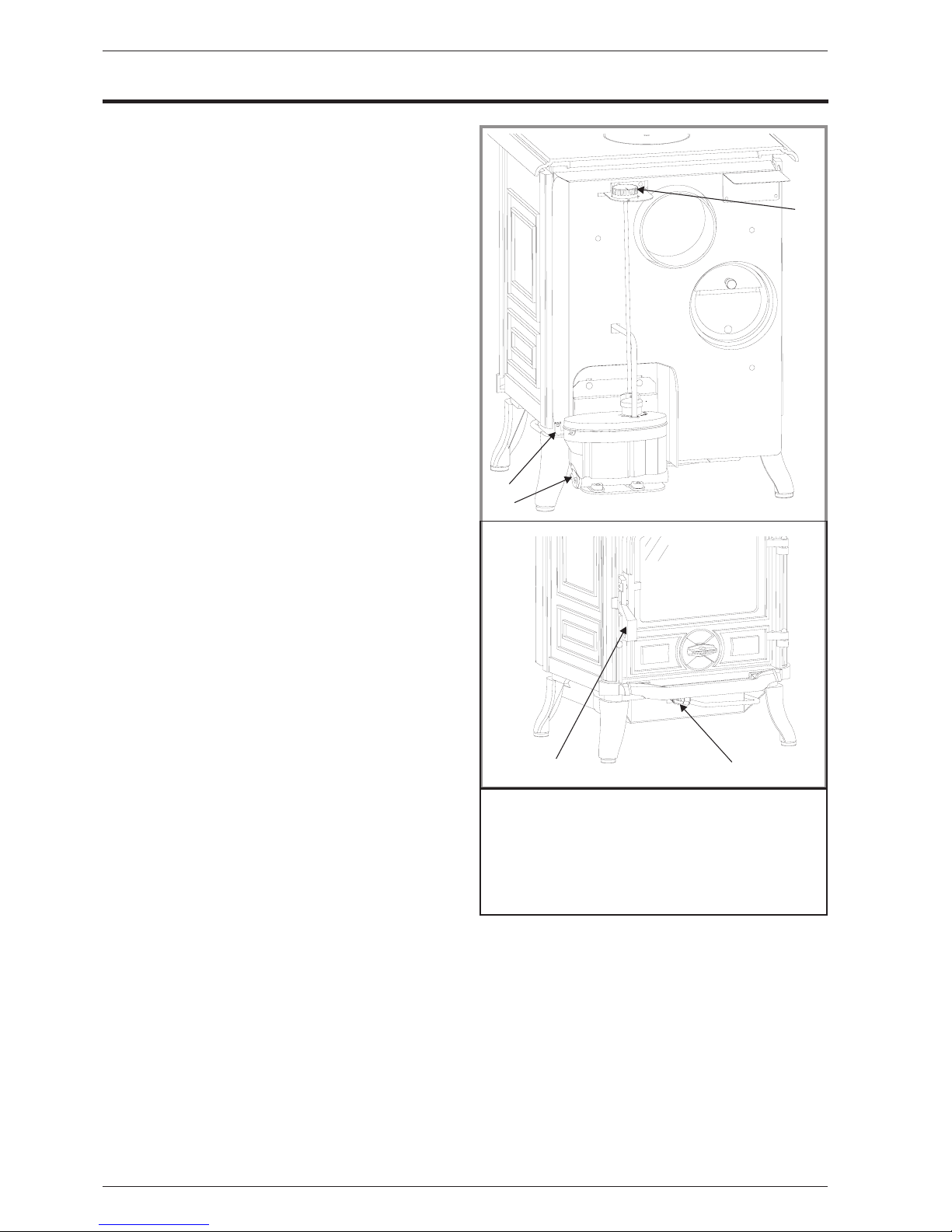
3.5.Maintenance of the stove
Every week : operate thede scaling lever (# 4,fig.14).
- Pull the rod,then push therod in rotating 360 degrees
two or three times (CAUTIO N : The rod is HOT).
Every3or4months: Clean the burner completely.
- Remove all the parts of the catalyser
(# 2, 3 and 4, fig. 3, p. 4)
- Using a soft bristle brush (a small clean paint brush),
carefully brush off the catalyser. Loosen any carbon
sootfromthebottomoftheburnerwitha puttyknife, and
vacuum clean. Ensure that thesmall air holes in burner
are free of carbon.
At least oncea year / End of heating season : Clean
or replace all the oil filters in the oil supply line.
To clean the filter of the float regulator
:
-settheregulationknobinclosedposition“0"
(# 1, fig. 14),
- turn off the tankvalve or the valve of the oil supply line,
- rai se the safety lever of the float regulator
(# 2, fig. 14),
- place a smallcontainer (or asmall rag) underthe float
regulator filter opening in order to collect the oil
contained in the float regulator,
- remove the filter cover plate located under the float
1
3
2
Figure 14 - Operating devices
1 - Regulation knob.
2 - Safety lever.
3 - Access to float regulator filter.
4 - De-scaling lever.
5 - Door handle.
4
5
Document n° 979-3 EN ~28/02/2000
174 05 05 BELFORT Oil fired stove
8 Technical manual

regulator (# 3, fig. 14) with a screwdriver,
- remove the tubular filter from thefloat regulator. Clean
it with oil using a soft brush, never a wire-brush,
- r eplace the filter in the float regulator, install the cover
plate and secure with the screw.
Clean all the enamelled panels of the stove with a dry
or slightly damp soft cloth.
Use a soft clean cloth to wipe the frontglass when the
unit is running at a low burning rate. When the main
door is opened for cleaning, the flame will be disturb,
and turn to a yellow flame. Clean quickly, but gently.
Close the door, the flame will return to a normalburning
position.
N.B. : The appearance of cracks when burning the
enamelled units is quite usual and tends to disappear
when the appliance is cooling down. It should not be
considered as a defect but rather as a patina of the
enamel which does not affect its quality nor its service
ability.
3.6.Recommendation
The adjustment of the stove has been made at the
factory and checked by your installer. Any anomaly of
operation should be reported to him at once.
This room heater is a high heat producing appliance
and may cause severe burns if touched on the glass
front door, or on top directly over the burner - keep
children away - Do not use for drying wet clothing.
CAUTION : Never light the burner if there is oil in the
burner pot. Clean out oil before lighting.
Racing : An audible fluttering sound is an indication
that there istoo much oil in thepot burner and/ora lack
adequate draught.
- turn off oil supply and set the control knob in closed
position “0" (# 1, fig. 14, p. 8).
- until fire has decreased to proper burn rate.
Do not overfire : If the stove or chimney connector
starts to glow, you are overfiring.
Document n° 979-3 EN ~28/02/2000
Oil fired stove BELFORT 174 05 05
Technical manual 9
 Loading...