

FRANCO BELGE Belfort, Savoy, Bourgogne, Burgundy Installation Manual

TECHNICAL
ABGO. 1 SIDINGS CLOSE, WEDNESFIELD ROAD, WOLVERHAMPTON. WV11 3DR
Oil Stove Installation
INSTRUCTIONS FOR FRANCO BELGE OIL STOVES

A Franco Belge oil stove is the result of many years of engineering research and design expertise. Before beginning the
task of installing the stove it should be remembered that it will be the major feature in any room when it is lit and will
continue to add character even when cold.
We recommend the installation of the stove is carried out by suitably qualified persons working to the Codes of
Practice issued by OFTEC and B&ES which are current at the time of installation. Our technically qualified staff will
happily answer any questions which are not covered by the literature delivered with the stove.
The installer is responsible under the Health and Safety at Work act 1974 vi the caustic nature of fire cement and the
possibility of disturbing asbestos and other materials such as ceramic in existing installations and to suggest
appropriate protection to be given to the person(s) carrying out the installation. The complete installation must be
carried out with due reference to the following Standards and Codes of Practice.
It should be noted that the requirements and these publications may be superseded during the life of this manual.
BS 799 Part Five, Specification for Oil Tanks.
BS 5410 Part One, Oil Firing Installations Up To 44kW.
BS 4543 Parts One & Three, Factory Made Insulated Chimneys.
Building Regulations: Part J England and Wales. Part F Scottish Regulations. Technical Booklet L for Northern Ireland
UK Distributor
Technical Support: 01902 790900
8.30- 5.30 during week days.
Email: sales@abgo.co.uk
Franco Belge Europe s.A.
127ieme RIF, 15 Zoning industriel Email: info@fbeurope.be
5660 Mariembourg
Burner Operation
The oil burner can be referred to as a dry burner. During the burning operation the burner base is dry of oil. As the
oil enters through the oil supply pipe it is vaporised by the heat reflected from the catalyser.
Under no circumstances should the appliance be operated with oil in the burner other than a small damp patch at
time of ignition.
The ability of the burner to burn correctly is dependent on the correct mix of fuel (oil) and oxygen (air).
These stoves are not suitable for installation on a boat. If you require an oil stove for a boat please contact ABGO for
further advice on suitable appliances and retailers.
These stoves should not be fitted in a bathroom or bedrooms where there is an increased risk of carbon monoxide
poisoning.

Competent Persons Regulations and Oil Technicians in England and Wales
The Government have introduced the Competent Persons Scheme in England and Wales to give an advantage to
operatives within the Construction Industry who are members of bodies that implement approved systems of
competence assessment and inspection.
It is designed to remove some of the burden of supervising work away from the Local Authority Building Control
Departments, so that they can concentrate on tracking down and prosecuting the ‘cowboy’ element within the
construction industry.
For the oil industry, the OFTEC Registration Scheme has been chosen to define competence. The Building Act of 1984
requires a person carrying out certain types of building work to give building notice or Building Regulation approval to
Building Control. This will involve payment of a fee to the Local Authority.
As from 1st April 2002, an amendment to Regulation 12 of the Building Regulations which covers Combustion
Appliances came into force. This exempts OFTEC Registered Installation, Commissioning and Servicing Technicians and
Tank Installation Technicians from the need to give notice and pay a fee when carrying out new installation work,
replacement work or making a major change to a system, in the areas covered by their class of registration. Registered
Technicians are required to keep a record of any work they undertake. OFTEC provides approved control documents
for installation work (CD/10) and commissioning work (CD/11).
It should be noted that the Building Regulations define installation work as including commissioning. An oil installation
will, therefore, require to be both installed and commissioned by a suitably qualified OFTEC Technician, if the need to
apply for a notice and pay a fee is to be avoided. The table overleaf shows which categories of technician can undertake
the various types of work covered by the new Regulations.
If you are qualified then you are competent to install this stove.
It is recommended that an audible carbon monoxide alarm is fitted as a precaution.
Order code: CO7B-10Y 10 YEAR CO ALARM
The carbon monoxide alarm should comply with BS EN 50291-1:2010, and must be installed to the manufacturers’
installation instructions, and current Buildings Regulations.
OFTEC
QUALIFICATION
INSTALL
COMMISSION
CONTROL
DOCUMENTATION
OFT 105 Appliance
Installation Technician
Appliance
Flues & Vents
Oil Lines & Fire Valves
Tanks
Heating Systems
-
-
Oil Lines & Fire Valves
Tanks
Heating Systems
OFTEC CD/10
OFT 101 Pressure Jet
Commissioning
Technician
-
Appliances
Combustion & Safety
Flues & Vents
Oil Lines & Fire Valves
Tanks
OFTEC CD/11
OFT 102 Vaporising
Commissioning
Technician
-
Vaporising Appliances
Combustion & Safety
Flues & Vents
Oil Lines & Fire Valves
Tanks
OFTEC CD/11
OFT 600A
Oil Lines & Fire Valves
Tanks
Oil Lines & Fire Valves
Tanks
OFTEC CD/10
The types of work covered under the new Part J Approved Document of the England and Wales Building Regulations
are new or replacement installations of boilers, oil tanks, associated pipe work, including the fitting of remote acting
fire valves and major changes to flueing systems.
Part L1 of the Regulations, which came into force at the same time, covers the energy efficiency aspects of heating
system installation, particularly their controls and requires commissioning to be properly undertaken and a certificate
completed by a competent person.
The Building Act falls under criminal law and there is a structured fining system for those who are found not to comply.
This is an important step which acknowledges those in the industry who work to Regulations and Standards and will
help customers recognise that OFTEC Registered Technicians have had their competence independently assessed.
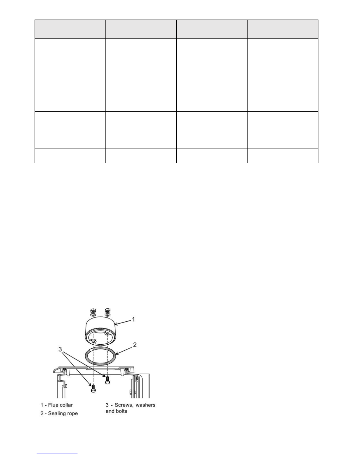
Flue Exit Direction – Belfort Oil Stove 174 05 06
Top Flue Exit
- Open the main door, remove the ceramic logs if fitted and
remove the internal baffle.
- Fix the sealing rope in the groove on the top and fit the
flue spigot using the two bolts and washers supplied,
ensuring there is a good seal.
- Replace the internal baffles.
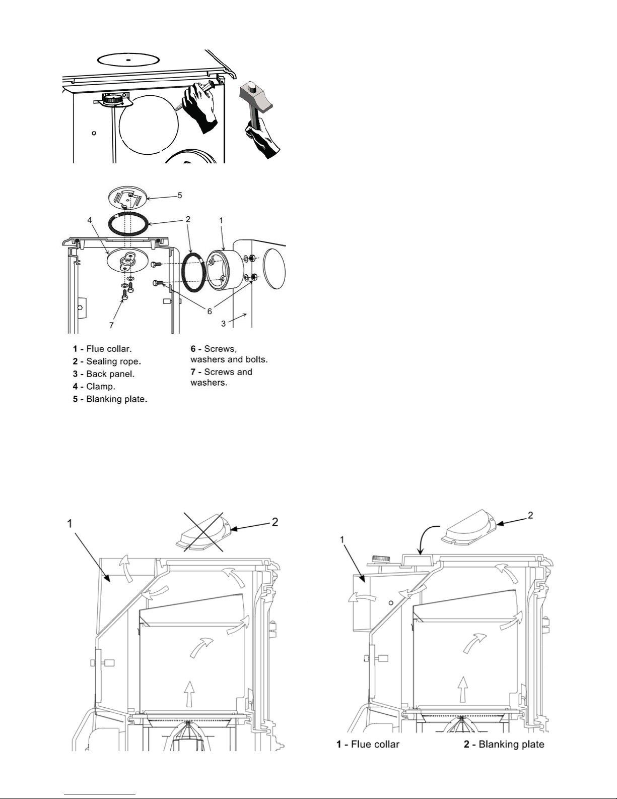
Rear Flue Exit
- The cut-out in the rear heat shield must be removed in the
case of using the rear flue exit and the heat shield removed
from the back of the stove.
- Open the main door, remove the ceramic log effect kit if
fitted and remove the internal baffle.
- Remove the blanking plate 5 and the clamp 4 from the
back and refit them on the top with the 2 screws and
washers supplied 7, ensuring there is a good seal 2.
- Set the ceramic rope in the groove and fix the flue
collar at rear with 2 bolts and washers supplied.
- Reinstall the internal baffles.
- Replace the rear heat shield.
Flue Exit Direction – Savoy Oil Stove 174 07 07
The flue collar/adapter can be fitted to give a rear or top flue exit. If using the top flue exit the blanking plate is not
required.
Flue Exit– Burgundy/Bourgogne Oil Stove 174 10 59
The stove has a top plate that lifts up to gain access to the simmering plate so there
is only a rear exit option for this model.
We recommend a “T” piece secured to the flue collar with a self-tapping screw.
Installation
Do not be tempted to fit the stove into an unsuitable fireplace. Beyond the requirements of Building Regulations and
providing suitable access to facilitate servicing the stove, providing a setting which will complement the stove is not a
luxury, it is the practicality of making the most of an investment. A good builder will be able to transform even the
most mundane of fireplaces, whether altering its proportions to those of the “Golden Mean” ideal, exposing a wooden
lintel, stone or simply removing superfluous detailing for comparatively small costs, and the result will be a pleasure
for many years.
Golden Mean
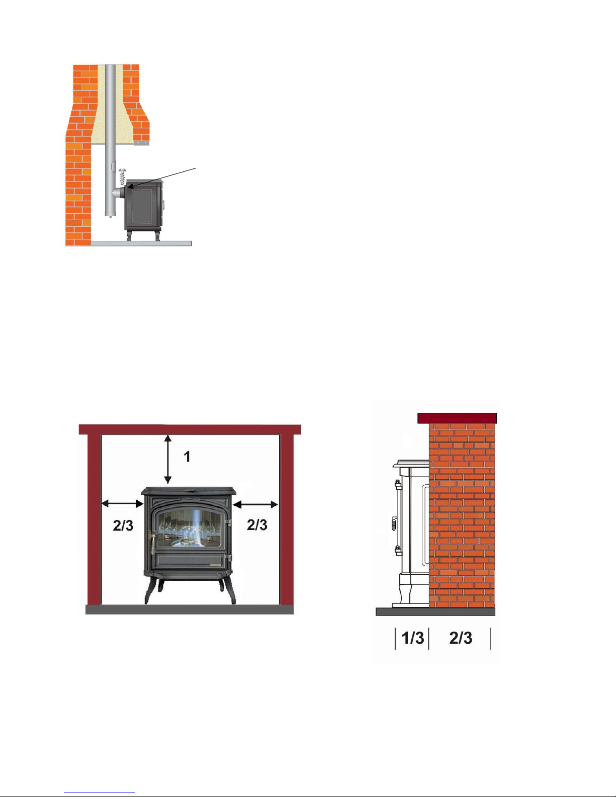
Minimum Installation Clearances
The measurements to combustible materials are
for advice only. In all installations surrounding
inflammable materials must not exceed 80°C and
therefore in certain circumstances they may need
to be increased.
The stove must always stand perfectly level and
have sufficient space allowed for commissioning
the stove and service work. This may lead to the
clearances to non-inflammable materials also
being increased from those in the tables below.
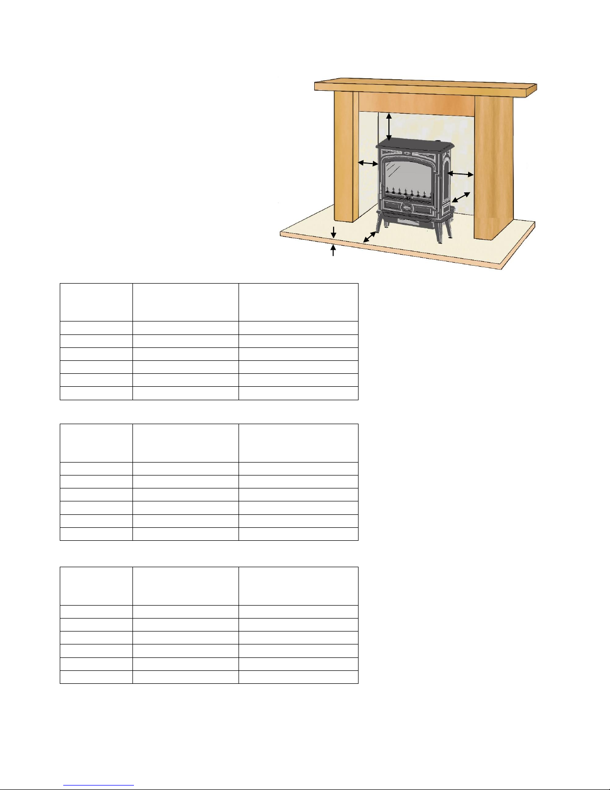
* The stove is supplied with a cast iron
hearth plate, which we strongly recommend
that you use to protect the surface below. It
is also the minimum non-inflammable
thickness required for installation.
⧫ This is the minimum distance in front, at
floor level, from the base of the stove. All
combustible materials above floor level in
front of the appliance must be a minimum
distance of 500mm away or any
combustible materials must not exceed
80°C.
Belfort
Minimum clearance
from combustible
materials
Minimum clearance
from non-inflammable
materials A 450mm
300mm
B
200mm
150mm
C
225mm⧫
225mm
D
200mm
150mm
E
200mm
150mm
F
12mm*
12mm*
Savoy
Minimum clearance
from combustible
materials
Minimum clearance
from non-inflammable
materials A 450mm
300mm
B
200mm
150mm
C
225mm⧫
225mm
D
200mm
150mm
E
200mm
150mm
F
12mm*
12mm*
Burgundy/
Bourgogne
Minimum clearance
from combustible
materials
Minimum clearance
from non-inflammable
materials A 450mm
300mm
B
300mm
150mm
C
225mm⧫
225mm
D
300mm
150mm
E
300mm
150mm
F
12mm*
12mm*
F
C
A
E
B
D
The Flue
There is often confusion as to the terms “flue” and “chimney” and for the purposes of this manual we define whatever
duct conveys the products of combustion as the flue, and the term chimney to mean any masonry structure within
which the flue may be contained. It is upon the flue’s ability to provide a consistent negative pressure or “flue draught”
that the efficiency and reliability of the stove will depend and it is therefore important to understand what can affect
the flue’s performance and how to ensure the flue installation provides your stove with the optimum operating
conditions.
However well the oil valve is calibrated, good combustion is dependent upon the correct amount of air being supplied
to the stove at all times and this is ultimately dependent on a correct and stable negative flue pressure. The initial
“flue draught” is created by the gas confined within the flue being hotter and therefore lighter than the air outside the
flue. The tendency for the hot gas to move up the flue is proportional to the height of the flue since the difference in
weight of equivalent columns of air and flue gas is greater the higher the column. Whilst this may be theoretically true,
in practice, because the temperature of the flue gas is cooled through the wall of the flue and the flow is slowed by
the friction of the internal surface of the flue, the benefits of extreme flue heights are negated. The need to minimise
the fluctuating effects of wind by having very hot flue gas temperatures inducing the greatest possible constant
negative pressure within the flue, conflicts with the ideal of utilising all the heat generated within the stove for heating.
The compromise is to ensure that whatever heat it is necessary to expend on creating a gas flow within the flue, the
flue makes the most efficient use of this heat by being constructed with an internal surface as smooth as possible and
by being thermally insulated. Both these requirements can be met in an existing chimney by lining it with a stainlesssteel oil liner insulated with vermiculite or mineral wool, and where no chimney exists, twin walled insulated stainlesssteel flue systems are available.
If there is an existing flue liner this should be replaced whenever a new appliance is fitted
In all installations the flue diameter must be the same diameter as the flue spigot on the stove so in all cases this will
mean lining an oversized masonry chimney or clay pot lined flue with a suitable flue liner. A minimum of 4m high or
taller.
Atmospheric Influences
To control these, the stove is fitted with a draught stabilizer (barometric damper). When the negative pressure
approaches the desirable upper limit the stabiliser opens, drawing air directly into the flue to supplement the flue
gases coming from the stove, thereby reducing the negative pressure to within its limits. When the wind speed
decreases the stabiliser will close to return the full negative pressure of the flue to the stove.
When the stove is commissioned the negative pressure within the stove is measured and the
stabiliser is adjusted to suit the characteristics of the flue, ensuring it gives the optimum
control.
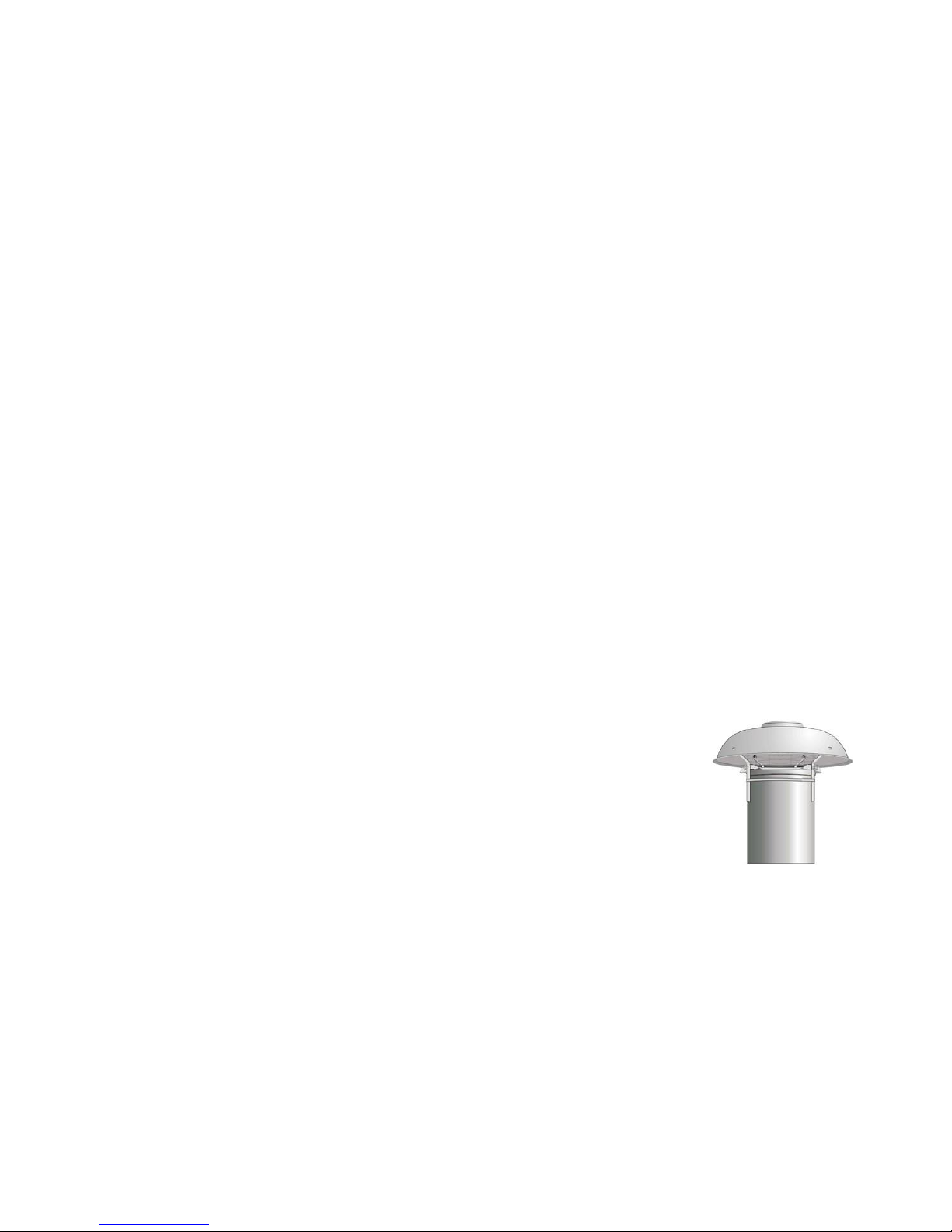
If the chimney draught is excessive, a secondary draught stabiliser (barometric damper) may
be installed to the first section of flue pipe. This will be set to open when the stabiliser on the
stove has fully opened. A wind “smoothing” cowl may also be fitted to the flue terminal as
wind blowing across the flue terminal will increase the negative pressure within the flue proportionately to the wind
speed.
If the chimney has any downdraught tendency, due to its position in relation to nearby obstacles, an anti-downdraught
cowl must be installed on the chimney or the chimney height may have to be increased.
Any smell of flue gases within the house should be investigated immediately.
Ventilation
The ventilation to provide the stove with air has to be regarded as an integral part of the
flue system, because unless the air passing through the flue is replaced with equal
amounts of air entering the house, the flue will cease to function. The cooler the outside
temperature and the harder the stove is working to maintain the required temperature
inside, the cooler the incoming air and the greater its flow. Strategically positioned,
correctly sized and baffled vents will avoid any discomfort from draughts in the room. If
the vent is directly behind the stove then an internal baffle is recommended.
Any room or space containing an appliance should have a permanent ventilation
opening of free area at least 550mm sq. for each kW of rated. In older dwellings, pre2008, with an air permeability which is greater than 5.0m3 /hr /m2 the first 5Kw may be
ignored.
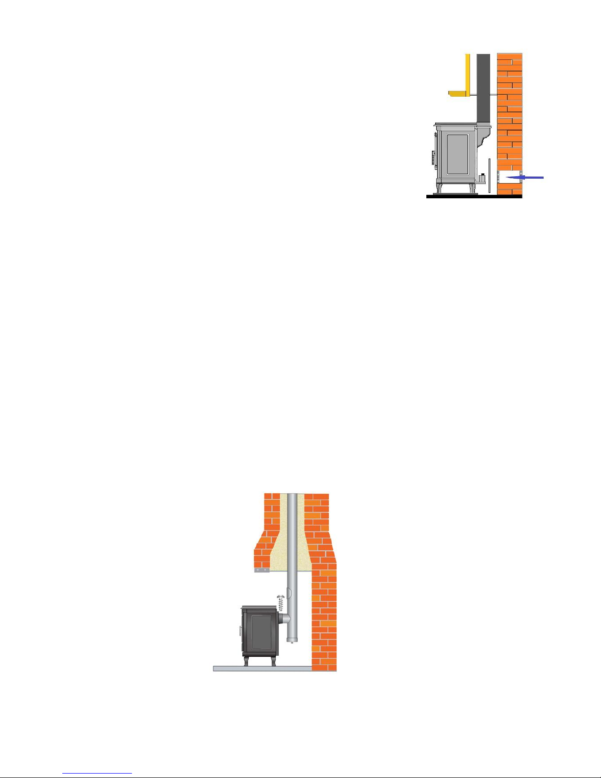
The Flue and Connections
Bends in flue pipe
Top exit
A flue shall have no more than four bends, each providing a maximum change of direction of 45°, there should be not
more than two of these bends before an access point for sweeping and two between a sweeping point and the flue
terminal.
On top exit stoves, ideally, the flue should rise vertically 1 meter before the first bend. It is however permissible to
have a bend no greater than 45° from the top flue outlet, or off the top of a “T” pipe, as long as it does not adversely
affect the flue draught.
Back exit
For a rear-outlet application using a T pipe, this should be treated as two 45º bends. If a “T” piece is to be used, the
horizontal flue run from the back outlet of the stove shall only be used to connect the stove to a “T” pipe and shall not
be more than 150mm in length.
If, due to the location of the stove, the horizontal run is marginally greater than 150mm then it permissible as long as
it is not detrimental to the flue draught requirements of the appliance. It must be noted that the flue draught will take
longer to establish the greater the horizontal length of flue and the sooting up of the glass on lighting will be greater.
 Loading...