

FRANCO BELGE ARDENNES 134 15 02 Installation Instructions Manual
Description of the appliance
Installation instructions
Operating instructions
Spare parts
Warranty certificate
Document n° 1220-2 ~ 16/03/2007
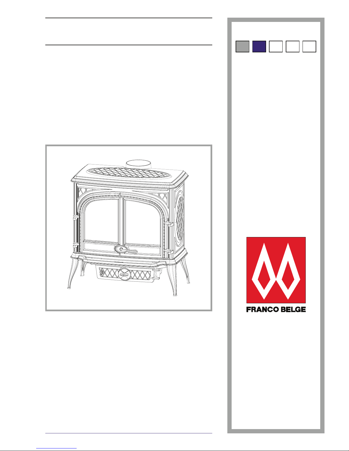
ARDENNES
Wood stove
EN 13240
Model : 134 15 02
Output : 15 kW
ENFR NL IT
Technical manual
to be saved
by the user
for future reference
STAUB FONDERIE
SARL with the capital of 6 359 540
Head Office Address
2, rue Saint Gilles
68230 TURCKHEIM
RCS Colmar
SIREN 444 881 953
Address
Administration and manufacturing
BP 73
59660 MERVILLE (FRANCE)
Telephone : 00 333 28 43 43 00
Fax : 00 333 28 43 43 99
Subject to modifications.
2 Technical manual “1220”
“ARDENNES” - model 134 15 02
CONTENTS
Description of the unit . . . . . . . . . . . . . . . . . . . . . . . . . . . . . . . . . . . p. 3
Package . . . . . . . . . . . . . . . . . p. 3
Specifications . . . . . . . . . . . . . . p. 3
Appliance description . . . . . . . . . . p. 3
Operating principle. . . . . . . . . . . . p. 3
Installation instructions . . . . . . . . . . . . . . . . . . . . . . . . . . . . . . . . . . p. 4
Warning to the user . . . . . . . . . . . p. 4
Location of the unit . . . . . . . . . . . p. 4
Chimney . . . . . . . . . . . . . . . . . p. 5
Mounting the flue collar . . . . . . . . . p. 5
Mounting the tray . . . . . . . . . . . . p. 5
Chimney connector . . . . . . . . . . . p. 6
Pre-utilisation check . . . . . . . . . . . p. 6
Maintenance of the Chimney . . . . . . p. 6
Instructions for user . . . . . . . . . . . . . . . . . . . . . . . . . . . . . . . . . . . . p. 7
Fuel . . . . . . . . . . . . . . . . . . . . p. 7
Lighting . . . . . . . . . . . . . . . . . . p. 7
Operating procedure . . . . . . . . . . . p. 8
De-ashing . . . . . . . . . . . . . . . . p. 8
Maintenance of the Chimney . . . . . . p. 8
Maintenance of the stove . . . . . . . . p. 8
Safety advice . . . . . . . . . . . . . . . p. 8
Trouble shooting . . . . . . . . . . . . . p. 9
Spare parts . . . . . . . . . . . . . . . . . . . . . . . . . . . . . . . . . . . . . . . . . p. 10
FRANCO BELGE congratulates you on your choice.
FRANCO BELGE, guarantees the quality of its appliances and is committed to meet its
customers’ needs.
FRANCO BELGE, which can boast a 80-year experience in the industry of heating devices, uses
state-of-the-art technologies
to design and manufacture its whole range of products.
This document contains instructions on how to install your appliance and make full use of its
functions, both for your comfort and safety.
This appliance is meant to burn wood safely
WARNING
Incorrectly installed, this appliance can be dangerous and possibly cause serious accidents.
We recommend that you engage the services of a professional engineer for its installation
and the regular maintenance requirements.
1 Description of the unit
1.1 Package
•
1 package : Stove
1.2 Specifications
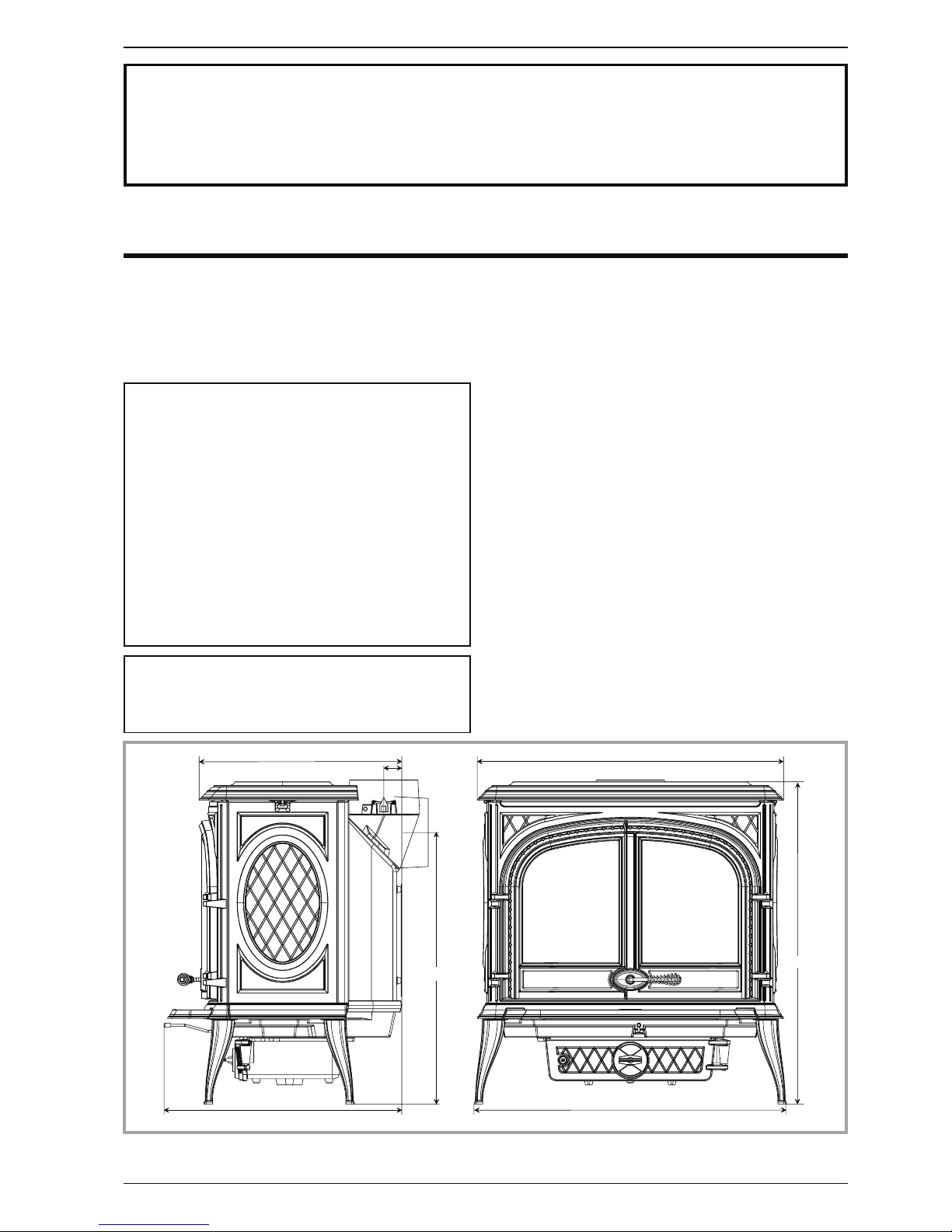
Model. . . . . . . . . . . . . . . . . . . 134 15 02
Hearth dimensions
(combustion chamber)
- Width . . . . . . . . . . . . . . . . mm 587
- Depth . . . . . . . . . . . . . . . . mm 343
- Height . . . . . . . . . . . . . . . . mm 300
Logs dimensions
- Depth maxi . . . . . . . . . . . . . cm 57
Ash pan capacity . . . . . . . . . . litre 5
Weight . . . . . . . . . . . . . . . . . kg 180
Heated volume . . . . . . . . . . . . m
3
650
- Chimney draught required . . . . . Pa 12
- Nominal Heat Output . . . . . . . . kW 14,9
- Flue mean gas temperature. . . . . C° 254
- Efficiency . . . . . . . . . . . . . . . % 77,3
- Co (13% O2) . . . . . . . . . . . . . % 0,23
Note : The indicated performances result from tests
carried out in accordance with standard EN 13240
with logs of Ø 12 cm, of depth 40 cm and a draught of
12 Pa, fuel mass of 5 kg.
1.3 Appliance description
Wood stove - in conformity with EN 13240
•
intermittent-burning heating appliance.
•
De tacha ble flue s pigot for rea r or to p ch imney
connection.
• Front loading door fitted with large refractory glass
panel.
•
Adjustable air control for controlling the burning rate.
• Large ash-pan.
• Long lasting burning cycle : When the appliance is
loaded with à 14 kg of dry wood (primary air inlet
closed, rep. B, fig. 5, page 7) with a 6 Pa draught, it
runs for 7 hours.
1.4 Operating principle
The “ARDENNES” is designed for operating only with
the door closed. Heat is mainly diffused by radiation,
through the window and body of the appliance.
Technical manual “1220” 3
“ARDENNES” - model 134 15 02 Description of the unit
5 7 2
6 5 5
4 8 7
4 3
7 3 7
7 5 0
7 7 7
Figure 1 - Dimensions in mm
2 Installation instructions
2.1 Warning to the user
All the l oca l and nat ion al reg ulations, a nd in
particular those relating to national and European
standards, must be observed when installing the
appliance.
An incorrectly installed hea ting app liance can
cause serious accidents (chimney fires, burning of
plastic insulation materials, in partition walls, etc.).
Th e insulati on of both th e appli ance an d the
exhaust gas pipe has to be reinforced and done
ac c or d in g t o th e S t an d ar d s an d t h e Bu i ld i ng
Regulations for safety reasons. The installation must be
carried out according to the Standards and the Building
Regulations.
Failure to respect the mounting instructions leads to
eng a g e the responsibili t y of th e one doing th e
installation.
The manufacturer’s responsibility shall be limited to the
supply of the appliance.
2.2 Location of the unit
Ventilation : For satisfactory appliance operation with
a natur a l dr a ught, chec k th a t su ffici e nt ai r fo r
co m busti o n is ava ilabl e in t h e ro om. In ho uses
eq u i pped with on e VM C (con t r olled mechan i c al
ventilation), this one aspire and renew the ambient air;
in this case, the residence is under slight low pressure
and a non -sealab le ext ernal air i ntake must be
installed in addition to the chimney itself, at least 50cm²
in section.
Position of the unit : For new installations, select a
central position within the house, to provide a good heat
distribution around the building. The heat distribution
towards the other rooms will be made through the
communicating doors. These rooms must be at low
pressure or fitted with non-adjustable air registers,
pl aced so th at they can not b e obstr ucte d, to
encourage circulation of the hot air.
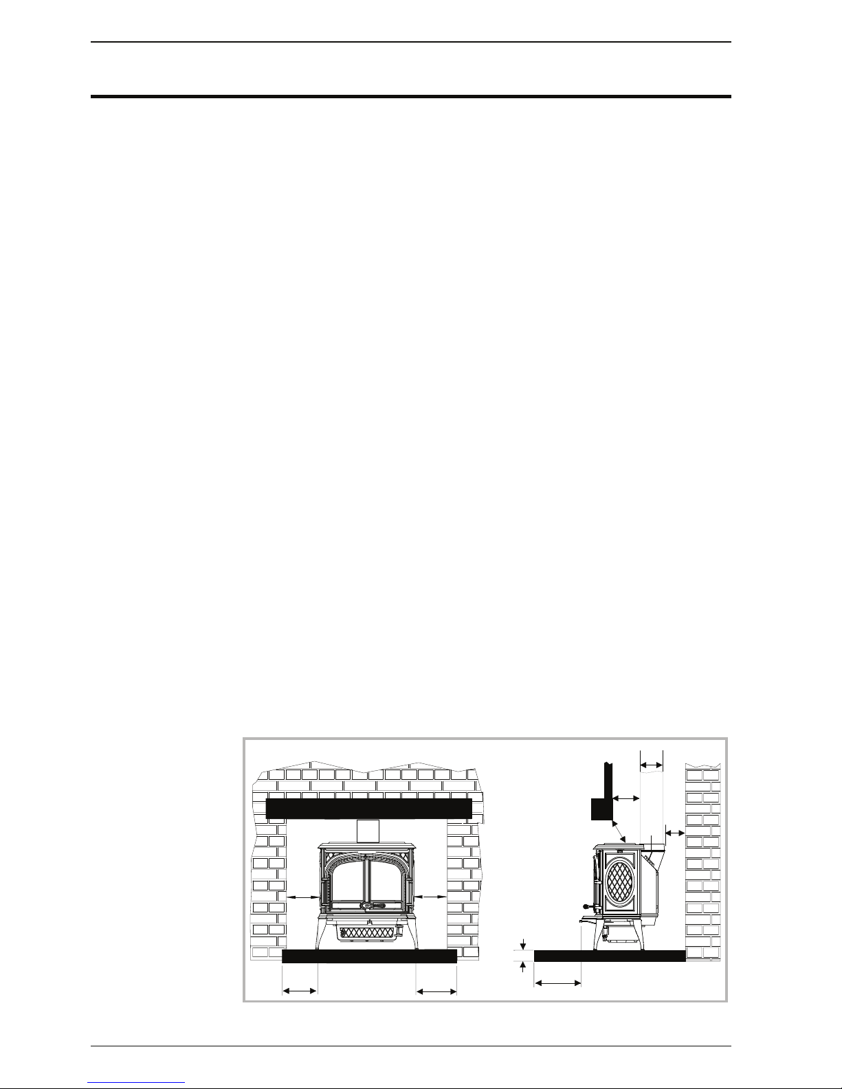
Floor and walls : Make sure there are not combustible
or covered with combustible material. Otherwise it must
necessary to install a non-combustible protection.
T h er e m u st be a
clearance of at least 150
mm at each side of the
appliance and at the back
of the appliance from a
non - c omb u s t ibl e w a l l.
Th i s di s tance m u s t be
extended to a minimum
clearance of 400 mm from
a n y c o mb u s t i b le
m a te r i a l s . T h is
me a s ure m e nt ma y b e
re duced to a mini m um
gap of 50 mm when the
non-combustible wall is at
least 200 mm thick.
There should ideally be a
minimum gap of 300 mm
at the right hand side of
the stove, this will ensure
the best possible access
to the loading door. When using a single wall flue pipe,
there must be a clearance (A) of at least three times its
diameter (B) from any combustible materials. If the
appliance has to be located in an opening, this distance
must be extended to a minimum clearance (A) of 450
mm from the pipe or the stove body to any combustible
materials.
Hearth : The appliance must stand on a fireproof
hearth.
It is possibl e to provide a he arth made of no n
combusible board/sheet material or tiles at least 12 mm
thick (C).
Constructional hearths should be constructed of solid
non combusti ble m aterial at le ast 1 25 mm thic k
(including the thickness of any non combustible floor
under the hearth).
The hearth must protrude at least 300 mm in front of the
stove and 150 mm each side.
Hearths are provided to prevent combustion appliances
setting fire to the building fabric and furnishings and to
limit the risk of people being accidentally burnt.
Therefore, they should be separated from adjacent
combustible materials and should be satisfactorily
delineated from surrounding floor finishes (carpets etc.)
as follows.
Combustible material should not be placed under a
constructional hearth for a solid fuel appliance within a
vertical distance of 250 mm from the upper surface of
the hearth, unless there is an airspace of at least 50 mm
between the combustible material and the underside of
the hearth.
Where a superimposed hearth has been placed onto a
constructional hearth, combustible material placed on
or besid the constructional hearth should not extend
under the superimposed hearth by more than 25 mm or
closer to the appliance than 150 mm.
E n su r e t h at t h e h e a r t h (s u p e r i mp o s e d or
constructional) is suitably delineated to discourage
combustible floor finishes from being laid too close to
the appliance, by marking the edges or providing a
change of level.
4 Technical manual “1220”
“ARDENNES” - model 134 15 02 Installation instructions
1 5 0
1 5 0
1 5 0
3 0 0
1 5 0
B
A
A
C
1 5 0
Figure 2 - Minimum clearances

Po s i t ion th e app l i ance on the hearth such that
combustible marerial cannot be laid closer to the base
of the appliance than :
(a) At the front, 300 mm if the appliance is an open
fire or stove which an, when opened , be operated as
an open fire, or 225 mm in any other case ;
(b) At the back and sides, 150 mm or in accordance with
the recommendations below which relate to distance
from hearth to walls. Please refer to section J of the
Building regulations
When using a single wall flue pipe, there must be a
clearance (A) of at least 450 mm from any combustible
materials (timber mantel, girder).
2.3 Chimney
Existing flue :The chimney must comply with Current
Building Regulations. If in doubt, consult your Dealer or
local Building Inspector.
-
The flue must be in good condition and must provide
sufficient draught (refer to technical details p. 3).
-
The flue must be suitable for the installation of fuel
burning appliances, otherwise it must necessary to
install a tubing.
-
The flue must be clean. It should be swept to remove
soot and dislodge tar deposits.
-
The flue must be well insulated. If the flue inner wall
surfaces are cold, a good thermal draw is impossible
causing condensation problems (tar formation etc) to
occur.
-
The flue must be watertight.
-
The flue must not be shared with other appliances.
- The chimney must have a constant cross section.
- When the cross-section of the chimney is too large, it
has difficulties in obtaining a good draught.
-
The chimney must be at least 4.5 m (15 ft) high and be
at 40 cm above the ridge of the roof and 8 meters away
from any construction.
-
In case of a flat roof or when the roof gradient is lower
than 15°, the stack must be 1,2 m (4 feet) high at least.
- The capping must not restrain the draught.
- If the chimney has any down draught tendency, due to
its position in relation to nearby obstacles, then an
anti-down draught cowl must be installed on the
chimney or the chimney height must be increased.
- If the chimney draught is excessive or irregular, a
draug ht sta bil izer (baromet ric da mper) must be
installed to the connector pipe it must be visible and
accessible.
Chimney to be built / New flue : The chimney must
comply with Current Building Regulations. If in doubt,
consult your Dealer or local Building Inspector.
- The appliance must not support the weight of the flue.
-
It must be distant from any combustible material
(walls, cross members)
-
It must permit an easy sweeping.
2.4 Mounting the flue collar
The stove is supplied with a connection flue spigot with
an inner diameter of 125 mm and an outer diameter of
139 mm.
Figure 4
All you have to do is removing adaptator (# 2) from the
spigot (# 1); unscrewing the adaptator and turning it at
180°. Replace the spigot onto the adaptator in leaving
an easy access for the exhaust valve control (# 3).
Ensure that the seal is fitted correctly.
2.5 Mounting the tray
To avoid damage during transport, the tray has been
stored behind the main door (figure 3).
Centre the tray on tab “A” and lower into place.
Technical manual “1220” 5
“ARDENNES” - model 134 15 02 Installation instructions
A
Figure 3 - Mounting the tray
1
2
3
1 8 0 °
Figure 4 - Mounting the flue collar
 Loading...