

FRANCO BELGE 174 10 54 Le Beffroi Technical Manual
Le Beffroi
Oil fired stove
Model 174 10 54
Document n° 954-6 ~ 29/04/2004
EN NO
Technical manual
to be saved
by the user
for future reference.
Description of the appliance
Installation instructions
Operating instructions
Spare parts
Warranty certificate
STAUB FONDERIE
Head Office Address
2, rue Saint Gilles
68230 TURCKHEIM
RC Colmar
SIREN 439 330 325
Address - Administration and
manufacturing
BP 73
59660 MERVILLE (FRANCE)
Telephone : 00 333 28 43 43 43
Fax : 00 333 28 43 43 99
Subject to modifications.

“Le Beffroi” ref. 174 10 54
FRANCO BELGE congratulates you on your choice.
FRANCO BELGE, which has been granted the ISO 9001 certification, guarantees the quality
of its appliances and is committed to meet its customers’ needs.
FRANCO BELGE, which can boast a 75-year experience in the industry of heating devices,
uses state-of-the-art technologies
to design and manufacture its whole range of products.
This document contains instructions on how to install your appliance and make full use of
its functions, both for your comfort and safety.
CONTENTS
Description of the unit ...................................p.3
Description . ...............p.3
Package :.................p.3
Optional equipment ...........p.3
Specifications . . . . . . . . . . . . . . p. 3
Operating principle. . . . . . . . . . . . p. 4
Installation instructions ..................................p.5
Position of the unit ............p.5
Chimney .................p.5
External tank ...............p.5
Chimney connector ...........p.6
Mounting the levelling feet .......p.6
Smoke exit at the top . . . . . . ....p.6
Smoke exit at rear ............p.6
Casing assembly. . ...........p.6
Levelling . . . . . . . . . . .......p.7
Oil flow adjustment . . . . . . . . . . . p. 7
Chimney draught. . . . . . . . . . . . . p. 8
Door closing pressure . . . . . . . . . . p. 8
Pre-utilisation check . . . . . . . . . . . p. 8
Mounting mirrors (Optional) . . . . . . . p. 8
Maintenance of the Chimney . . . . . . p. 8
Operating instructions ...................................p.9
Fuel . . . .................p.9
Lighting procedure ............p.9
Operating procedure...........p.9
Shutting down ..............p.9
Maintenance of the stove . . . . . . . . p. 9
Recommendation . . . . . . . . . . . . p. 10
Trouble shooting . . . . . . . . . . . . p. 11
Spare parts .........................................p.12
2 Technical manual “954”

“Le Beffroi” ref. 174 10 54 Description of the unit
This appliance is an oil-fired stove.
WARNING
An incorrectly installed oil-fired stove can cause serious accidents.
This appliance should only be installed by competent personnel.
1. Description of the unit
1.1. Description
Flued oil stove with vaporizing burner
(Norm EN1 - NF D 35-385).
1.2. Package :
1 stove
•
1 casing
•
Natural stone casing 72554
-
Enamelled panels :
-
Beige 72553 - Red 72605 - Blue 72606
Marble panels :
-
Black 72805 - Beige 72806 - Gray 72807
1.3. Optional equipment
Brass-rampe : KR 134 08.
•
Mirrors : P 174 10 53
•
•
Vent-pipe.
1.4. Specifications
Model ................. 1741054
Nominal heat output ........kW 10
.................BTU/hr 34130
Oil consumption at :
- maximum speed .........l/h 1,20
..................gal/hr 0.317
- minimum speed ........litre/h 0,25
..................gal/hr 0,066
Chimney draft required at :
- maximum speed .........Pa 14
- minimum speed .........Pa 5
Weight ................kg 138
5 6 4
2 1 4
6 0 4
Ø 1 2 0 / 1 2 5
1 0 5 29 1 5
6 2 4
Fig. 1 - Dimensions in mm
Technical manual “954” 3
“Le Beffroi” ref. 174 10 54 Description of the unit
1
2 a
2
2 b
2 c
3
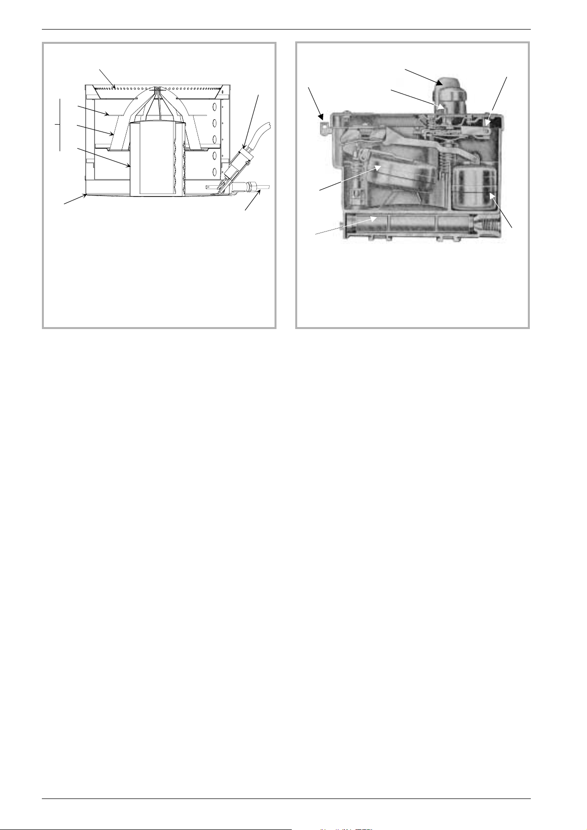
1 - Air holes
2 - Catalyser
2a : Upper ring
2b : Catalyser top
2c : Catalyser body
3 - Burner pot
4 - Automatic ignition
(optional)
5 - De-scaling lever
Figure 2 - Burner
A
4
B
F
E
C
5
G
A - Control knob
B - Safety lever.
C - Main float
D - Safety float
Figure 3 - Float regulator
E - Oil level regulator
F - Thermostat control
G - Filter
D
1.5. Operating principle
Furnace oil is fed to the burner floor (fig. 2) where is it
ignited by means of a firestarter. The heat produced by
this flame brings the burner temperature to the required
level to vaporize the fuel. Oil will only burn as a vapour
not a liquid.
Room combustion air enters the burner through the air
inlet holes (# 1).
In the center of the burner is the catalyser (# 2) which
aids in vaporizing the fuel. When the stove is operation,
the catalyser glows red. The stove should not be used
with out both the catalyser (# 2c), catalyser top (# 2b)
and ring (# 2a).
A de-scaling lever (# 5) can be pushed and pulled in and
out as well as turning slightly at the same time to keep
the inlet pipe clear of carbon buildup.
The stove float regulator (fig. 3) contains a filter (# G) to
trap impurities.
A safety lever (# B) controls fuel flow. Oil can only enter
the float chamber when the safety lever is depressed.
Oil temperature variations will affect the oil flow into the
float chamber. A float in the chamber raises the fuel
level available to the burner.
The carburetor is also controlled by a control knob
which turns from “0" (off) to ”6" (high setting).
A draft regulator (# 1, fig. 11) ensures a constant air
intake to the burner regardless of external factors.
4 Technical manual “954”
“Le Beffroi” ref. 174 10 54 Installation instructions
2. Installation instructions
SAFETY NOTICE : Read carefully all instructions
before starting the installation. If the stove is not
properly installed, a house fire may result. For your
safety, follow the installation directions. Contact local
building or fire officials about restrictions and
installation inspection in your area.
2.1. Position of the unit
The position of the appliance must be chosen very
-
carefully in order to obtain the best possible results for
heat distribution.
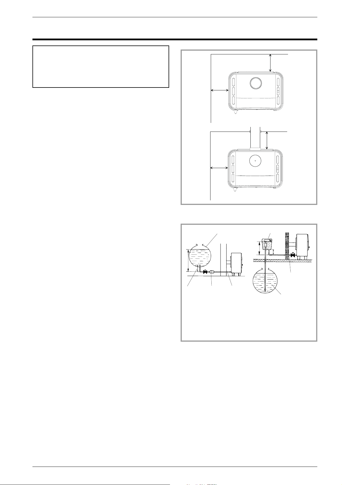
Position the unit to comply with the minimum
-
clearances to combustible material. Minimum
clearances are shown from the vertical portion of the
chimney connector. Check that no overhead cross
members in the ceiling will be cut. Reposition unit if
necessary, being careful not to move closer than the
minimum clearances.
Outside air : For the oil stove to function properly, an
-
adequate supply of combustion air is required.
200
mm
200
mm
200 mm
200 mm
2.2. Chimney
Ensure that the flue has sufficient draught (refer to
-
technical details).
Minimum flue diameter, 10 cm (4" I.D).
-
The chimney must be at least 4.5 m (15 ft high).
-
- The flue must not be shared with any other appliance.
-
Downdraughts caused by obstacles close to the
chimney top may sometimes be prevented by fitting an
anti-downdraught cap to the top of the chimney.
-
The chimney must have a constant cross section. Too
large a flue could affect the chimney draught.
-
The chimney must be soundly constructed, in order to
prevent cold air infiltration.
-
The flue must be well insulated, water and air tight. A
chimney with a cold internal surface can prevent a
good chimney draught and condensation will occur.
-
The flue must be swept at least once a year.
2.3. External tank
A barometric fuel tank should not be positionned where
it will be in the direct rays of the sun or adjacent to a
source of intense heat.
If the tank is more than 8 ft (2,5 m) higher than the stove
a pressure reducer must be installed on the oil line.
If the tank is lower than the stove a lift pump will have to
be utilized.
A clearance of 6 “ (15 cm) must be maintained between
the external/remote tank and the stove.
Figure 4 - Minimum clearances
3
1
7
462
1 - 8 ft maxi
2 - At least 9,5 in.
3 - Oil tank
4 - Filter
1
Figure 5 - Oil supply
5
7
2
6
3
Technical manual “954” 5
 Loading...