

FRANCO BELGE 174 05 05 Technical Manual
Technical manual
to be saved
by the user
for future reference
Document n° 979-3 EN ~ 28/08/2000
Les Fonderies Franco-Belges
59660 MERVILLE
Phone : 03.28.43.43.43
Fax : 03.28.43.43.99
RC Hazebrouck 445750565B
Subject to modifications
Belfort
Oil fired stove
Model : 174 05 05
(EN 1)
CAN/CSA approved / ANSI/UL approved
Description of the applia nce
Installation instructions
Operating instructions
Spare parts
English
Norsk

CONTENTS
Description of the unit . . . . . . . . . . . . . . . . . . . . . . . . . . . . . . . . . . . . . . 3
Package....................3
Optional equipment ..............3
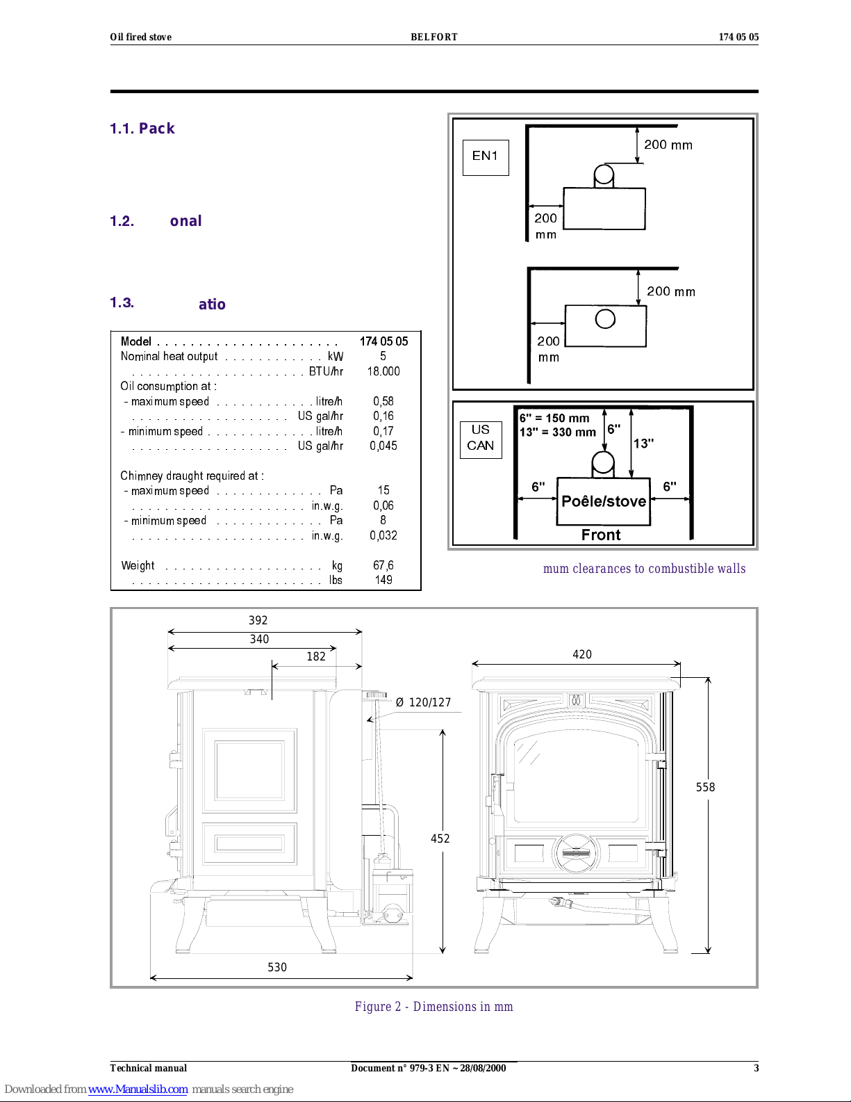
Specifications .................3
Description ..................3
Operatingprinciple ..............4
Installationinstructions...................................... 4
Positionoftheunit ..............4
Chimney ....................4
Mounting the levelling feet ..........5
Topflueoutlet.................5
Rearflueoutlet ................5
Chimney connector ..............5
Externaltank..................6
Levelling....................6
Pre-utilisationcheck .............6
Oilflowadjustment ..............6
Chimney draught ...............7
Doorclosingpressure ............7
Maintenance of the Chimney .........7
Operatinginstructions ...................................... 8
Fuel.......................8
Lightingprocedure ..............8
Operating procedure .............8
Shuttingdown.................8
Maintenance of the stove ...........8
Recommendation ...............9
Trouble shooting .............. 10
Spareparts.............................................11
FRANCO BELGE congratulates you on your choice.
FRANCO BELGE, which has been granted the ISO 9001 certification, guarantees the
quality of its appliances and is committed to meet its customers’ needs.
FRANCO BELGE, which can boast a 75-year experience in the industry of heating devices,
uses state-of-the-art technologies
to design and manufacture its whole range of products.
CONTENTS Page Page
Document n° 979-3 EN ~ 28/08/2000
174 05 05 BELFORT Oil fired stove
2 Technical manual
1. Description of the unit
1.1.
Package
¤ 1 package. The stove is supplied completely
assembled exceptthe fourlevelling feet that are placed
on the burner.
1.2.
Optional equipment
¤Groundvat
¤ Glow-plug ignitor
1.3.
Specifications
Model...................... 1740505
Nominalheatoutput............ kW 5
.....................BTU/hr 18.000
Oil consumption at :
-maximumspeed............litre/h 0,58
................... USgal/hr 0,16
-minimumspeed.............litre/h 0,17
................... USgal/hr 0,045
Chimney dra ught required at :
-maximumspeed............. Pa 15
..................... in.w.g. 0,06
-minimumspeed ............. Pa 8
..................... in.w.g. 0,032
Weight ................... kg 67,6
....................... lbs 149
Figure 1 - Minimum clearances to combustible walls
392
340
182
Ø 120/127
452
530
558
420
Figure 2 - Dimensions in mm
200 mm
200
mm
200 mm
200
mm
US
CAN
EN1
Document n° 979-3 EN ~ 28/08/2000
Oil fired stove BELFORT 174 05 05
Technical manual 3
1.4. Description
Flued oil stove with vaporizing burner
(Norm EN 1).
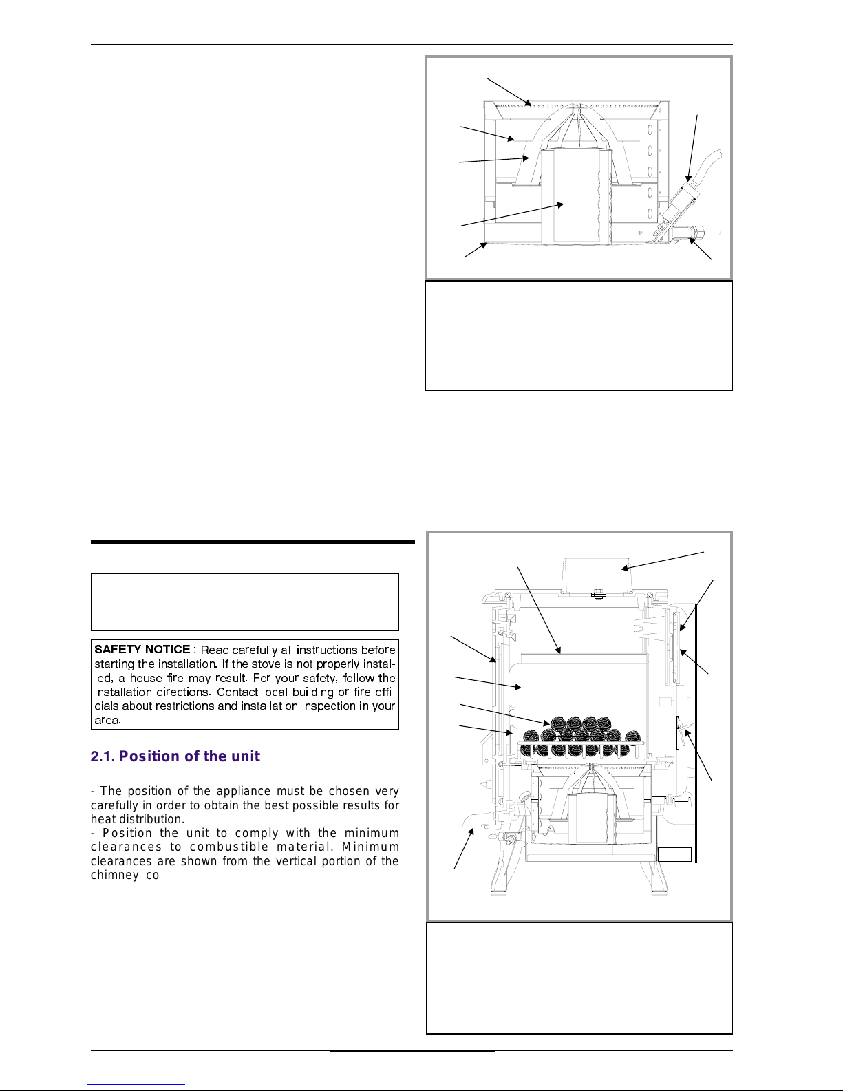
1.5. Operating principle
Furnace oil is fed to the burner floor (fig. 3) where is it
ignited by means of a firestarter (or t he Glow-plug
ignitor # 6). The heat produced by this flame brings the
burner temperatureto the required level to vaporize the
fuel. Oil will only burn as a vapour not a liquid.
Room combustion air enters the burner through the air
inlet holes.
In the center of the burner is the catalyser (# 4, fig. 3)
which aids in vaporizing the fuel. When the stove is
operation, the catalyser glows red. The stove should
not be used with out both the catalyser (# 4 , fig. 3),
catalyser top (# 3) and ring (# 2).
A de-scaling lever (# 7, fig.3) can be pushed and pulled
in and out as well as turning slightly at the same time to
keep the inlet pipe clear of carbon buildup.
The stove float regulator contains a filter to trap
impurities.
A safety lever controls fuel flow. Oil can only enter the
float chamber when the safety lever is depressed.
Oil temperature variations will affect the oil flow into the
float chamber. A float in the chamber raises the fuel
level available to the burner.
The float regulator is also controlled by a control knob
which turns from “0" (off) to ”6" (high setting).
A draught regulator (# 1, fig. 13, p. 7) ensures a
constant air intake to the burner regardless of external
factors.
2. Installation instructions
SAFETY NOTICE
: Read carefully all instructions before
starting the installation. If the stove is not properly instal-
led, a house fire may result. For your safety, follow the
installation directions. Contact local building or fire offi-
cials about restrictions and i nstallation inspection in your
area.
2.1. Position of the unit
- The position of the appliance must be chosen very
carefully in order to obtain the best possible results for
heat distribution.
- Position the unit to comply with the minimum
clearances to combustible material. Minimum
clearances are shown from the vertical portion of the
chimney connector. Check that no overhead cross
members in the ceiling will be cut. Reposition unit if
necessary, being careful not to move closer than the
minimum clearances.
- Outside air : For the oil stove to function properly, an
adequate supply of combustion air is required.
2.2. Chimney
- Ensure that the flue has sufficient draught (refer to
technical details).
1
2
3
4
5
6
7
Figure 3 - Burner
1 -Airholes
2 - Upper ring
3 - Catalyser top
4 - Catalyser
5 - Burner
6 - Glow-plug ignitor
(optional)
7 - De-scaling lever
1
2
4
5
3
6
7
8
9
10
Figure 4 - Description
1 - Blanking plate
2 - Main door
3 - Flue collar
4 -Baffle
5 -Tray
6 - Sliding door
7 - Supplementary baffle
8 - Draught control
9 - Ceramic coal
10 - C oal support
USA / CANA DA : The installation of this stove must
comply with state and localrequirements and the standard CSA B139.
Document n° 979-3 EN ~ 28/08/2000
174 05 05 BELFORT Oil fired stove
4 Technical manual
- Minimum flue diameter, 10 cm (4" I.D).
- The chimney must be at least 4.5 m (15 ft high).
- The flue must not be shared with any other appliance.
- Downdraughts caused by obstacles close to the
chimney top may sometimes be prevented by fitting an
anti-downdraught cap to the top of the chimney.
- The chimney must have a constant cross section. Too
large a flue could affect the chimney draught.
- The chimney must be soundly constructed, in order to
prevent cold air infiltration.
- The flue must be well insulated, water and air tight. A
chimney witha coldinternalsurfacecan prevent a good
chimney draught and condensation will occur.
- The flue must be swept at least once a year.
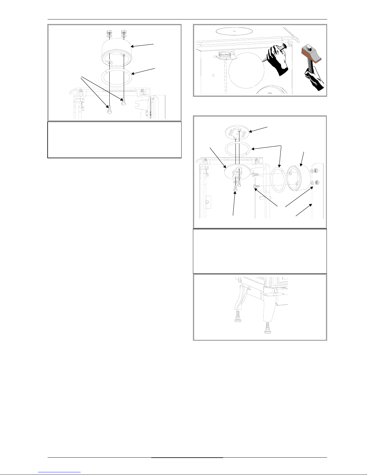
2.3. Mounting the levelling feet
Fit the 4 screws and the 4 caps supplied (on the
burner) into each leg of the stove (fig. 8).
2.4. Top flue outlet
Figure 5
- Open the main door, remove the ceramic coal grate
with theirs coal (# 9 and 10, fig. 4, p. 4) and remove the
internal baffle (# 4 and 7, fig. 4, p. 4).
- Fix the sealing rope in thegroove on the top and fit the
flue spigot using the two bolts and washers supplied,
ensuring there is a good seal.
- Replace the internal baffles.
The cut-out of therear heat shield must not be remove
in the case.
2.5. Rear flue outlet
Figure 7
- Open the main door, remove the ceramic coal grate
with theirs coal (# 9 and 10, fig. 4, p. 4) and remove the
internal baffle (# 4 and 7, fig. 4, p. 4).
- Remove the rear heat shield and the cut-out on it
(fig. 6).
- Remove the blanking plate 5 and the clamp 4 from the
back and refit them on the top with the 2 screws and
washers supplied 7, ensuring there is a good seal 2.
- Set the ceramic rope in the groove and fix the flue
collar at rear with 2 bolts and washers supplied.
- Reinstall the internal baffles.
- Replace the rear heat shield.
2.6. Chimney connector
- The appliance must be as close as possible to the
chimney. Avoid horizontal flue connection pipes which
can dangerously restrain functioning of the appliance.
- The connector pipe must be either 24 ga. black
painted or blued steel or 316 grade 20 ga. stainless
steel or 1 mm vitreous enamelled steel, with a
maximum diameter of 127 mm (5" O.D.). Single wall
3
1
2
Figure 5 - Top flue outlet
1 - Flue collar
2 - Sealing rope
3 - Screws, washers and
bolts
Figure 6 - Back panel
7
5
2
1
3
4
6
Figure 7 - Rear flue outlet
1 - Flue collar.
2 - Sealing rope.
3 - Back panel.
4 -Clamp.
5 - Blanking plate.
6 - Screws, washers and
bolts.
7 - Screws and washers.
Figure 8 - Levelling
Document n° 979-3 EN ~ 28/08/2000
Oil fired stove BELFORT 174 05 05
Technical manual 5
 Loading...