

FRANCO BELGE 134 10 09 Camargue, Camargue 134 10 09 Technical Manual
Camargue
Document n° 759-4 EN ~ 04/02/2000
Français
Wood stove
CGBfD-NFD35-376
Model 134 10 09
Outpout : 10 kW
English
Technical manual
to be saved
by the user
for future reference
Description of the appliance
Installation instructions
Operating instructio ns
Spare parts
Warranty certificate
Les F onde riesFranco-B el ges
59660 MERVILLE
Phone : 03.28.43.43.43
Fax : 03.28.43.43.99
RC Hazebrouck 445750565B
Subject to modifications

Ref. 134 10 09 Camargue Wood stove
CONTENTS
Page
Productinformation .................... 3
Package..............................3
Optional equipment .......................3
General characteristics .....................3
Description ............................3
Principle of operation ......................3
Installationinstructions.................. 4
Theroom .............................4
Flue ................................4
Connection to flue ........................4
Mounting the cast iron legs and the bottom heat shield ....5
Fitting of the handle .......................5
Assemblyoffluespigotandblankingplates..........5
Pre-utilisation check .......................6
Chimney maintenance and sweeping ..............7
Instructionsforuser .................... 7
Fuel ................................7
Instructionsforusewithwood..................7
Controloffire...........................8
Cleaning..............................8
Maintenanceofthestove ....................8
Trouble Shooting .........................8
Sparesparts......................... 9
2 Technical manual
Document n° 759-4 EN ~ 0 4/02/200 0
Wood stove Camargue Ref. 134 10 09
Warning to the user
A wood stove should only be installed by competent personnel, in the strict
application of normal practices and all safety precautions.
An incorrectly installed wood stove can cause serious accidents (chimney fires,
burning of plastic insulation materials, in partition walls, etc.).
The manufacturer’s responsibility shall be limited to the supply of the equipment.
1.Product information
1.1. Package
- 1 package : Stove complete.
1.2. Optional equipment
- Set of 4 high legs.
1.3. General characteristics
Reference .................... 1341009
Maximumoutput...............kW 10
Volumeheated ............... m
Draught require ment . . . . . . . . mm water 1.5 to 2
Grate dimensions:
-width ....................mm 450
-depth....................mm 230
- usable height . . . . . . . . . . . . . . . . mm 200
Max.logsize ................cm 38
Ash pan capacity . . . . . . . . . . . . . litres 3
Netweight ................ KGs 130
3
300to400
1.4. Description
Stove C G B f D - NF D 35-376
C : Continuous-burning wood-fired heater.
G : Wood burnt on grate.
B : Wood burning stove.
f : Enclosed combustion chamber with refractory brick
walls.
D : Removable appliance, to be installed near a wall.
• Detachable flue spigot for rear or top chimney
connection.
• Detachable top for easy handling and cleaning (rear
smoke exit only).
• Optional kit for burning solid smokeless fuels.
• Adjustable air controls for controlling the burning rate.
• Large ash-pan.
1.5.Principle of operation
The “Camargue” is designed foroperationwith the door
closed.
Heatis mainly diffused by radiation, through the window
and body of the appliance.
Combustion occurs on the grate, with draught entry
through the top of th e grate, which assists the
combustion of volatile materials helping to keep the
glass clean during normal operation.
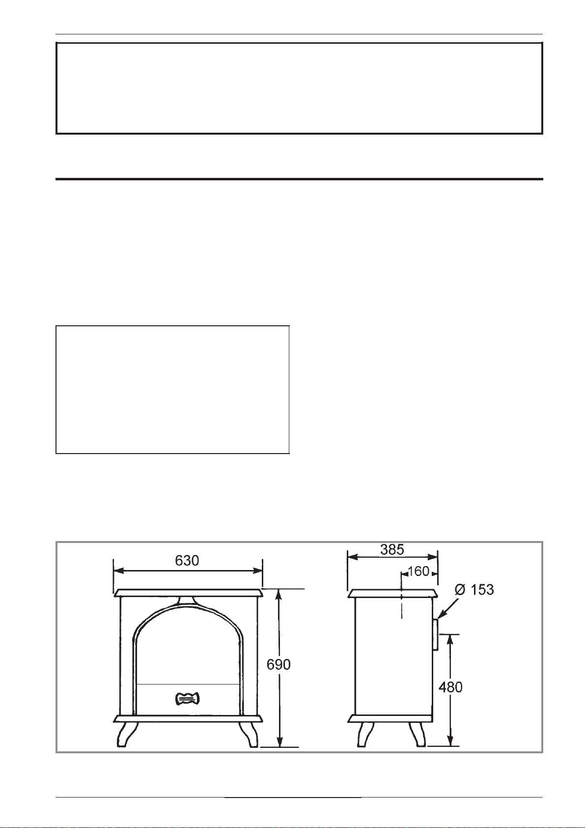
Figure 1 - Dimensions in mm
Technical manual 3
Document n° 759-4 EN ~ 04/02/2000

Ref. 134 10 09 Camargue Wood stove
2.Installation instructions
2.1.The room
Ventilation :
For satisfactory operation with a natural draught, check
that sufficient air for combustion is available in the
room.
Chimney position :
For new chimney installations, select a central position
within the building, to provide a good heat distribution
around the building.
Hearth :
The hearth must be suitable for use with solid fuel
burning appliances and must comply with Current
Building Regulations. If in doubt, consult your Dealer or
local Building Inspector.
Rear wall and ceiling :
The appliance mu st not be positioned close to
combustible materials, wall & ceiling surfaces etc.,
Consult your Dealer or local Building Inspector if in
doubt.
2.2. Flue
Existing flue :
- The flue must be in good condition and must provide
sufficient draught.
- The flue must be suitable for the installation of solid
fuel burning appliances and comply with Current
Building Regulations.
- The flue must be clean. It should be swept to remove
soot and dislodge tar deposits.
- The flue must be well insulated. If the flue inner wall
surfaces are cold, a good thermal draw is impossible
causing condensation problems (tar formation etc) to
occur.
- The flue must not be shared with other appliances.
- The recommended minimum flue height is 5 metres.
- If thechimney has any down draught tendency, due to
its position in relation to nearby obstacles, then an
anti-down draught cowl must be installed on the
chimney or the chimney height must be increased.
- If the decompression in the chimney is excessive, a
draught stabiliser must be installed.
Chimney to be built / Flue non-existent :
- The flue must not be supported by the stove.
-Consult a chimneyspecialistforadviceonsuitableflue
systems for solid fuel appliances.
- T he join betwee n the connection pipe and the
stovepipe, and the flue, must be leak tight.
- The connection pipe and any draught stabiliser must
have access for cleaning.
To avoid damageduringtransport, the fourlegs and the
bottom heat shield are not mounted when the stove is
shipped from the factory. These parts should be fitted
carefully to avoid damaging the appliance.
2.3.Connection to flue
The stove must be installed as close as possible to the
chimney.
- The stove should be connected to the flue by a smoke
pipe,approvedforinstallationwithcombustionproducts
(e.g. stainless steel 1 mm thick, 20g, or vitreous
enamel.).
- Pipe diameter must not be less than the appliance
spigot diameter.
- The connection can be either vertical or horizontal. For
horizontal connections, avoid right angle bends.
4 Technical manual
Document n° 759-4 EN ~ 04/02/2000
 Loading...