


Francis Searchlights Ltd
Union Road, Bolton
Lancashire, BL2 2HJ, UK
Tel: +44 (0) 1204 558960
Fax: +44 (0) 1204 558979
http://www.francis.co.uk
E-mail: sales@francis.co.uk
User Instruction & Installation Manual
L230 LED 78 Watt Searchlight
Product Reference Number:
Manufacturer’s details: Distributor details:
A6138-5K – 240v DECK
A6144-5K – 24v DECK
Manual Part Number: C27509
Issue: 1 6.3.17

CONTENTS
1 - Introduction
2 - Safety Precautions
3 - Technical Information
4 - Unpacking and Installation Instructions
5 - Electrical Installation
6 - Operating Instructions
7 - Fault Finding
8 - Maintenance and Servicing
9 - Wiring Diagrams & General Assemblies
10 - Spare Parts List
Back To Top

1 - Introduction
It is imperative that this manual is read carefully and understood before
installing your equipment. For your future reference please keep this manual in
a safe place.
Thank you for specifying a product from the Francis Searchlights range. All Francis products are
designed to give complete customer satisfaction and are manufactured to the highest engineering
standards in order to ensure optimum performance and service life.
The Francis LED range combines features proven over many years service in the most hazardous
conditions in both marine and land installations.
In order to prolong the life and performance of your product, we recommend that you only specify
Francis Searchlights spare parts. This will also ensure that any warranties on your equipment will
not be invalidated. Information on spares ordering and parts is provided in this manual.
Should you ever need to contact Francis Searchlights Ltd. regarding your equipment, please quote
the Product Serial Number at all times.
Back To Top

2 - Safety Precautions
The following instructions must be adhered to, in order to ensure a safe working environment and
the safety of the user.
Note: When unpacking or manoeuvring the searchlight into its fixing position, suitable
lifting points must be used in order to prevent damage to the equipment or personal injury.
The high luminance of the LED can cause severe damage to the eye if viewed directly.
ALWAYS wear suitable protective goggles when viewing the LED;
Searchlights get hot. Never touch the unit when lit and always allow 15 to 20 minutes for
cooling down after turning the searchlight off;
Never place anything on or cover the searchlight when in use;
Ensure the LED has cooled sufficiently before removal;
Due to the vast range of LED modules available it may appear possible that more powerful
LED’s can be used in the equipment than for which it was designed. Even when the unit will
physically accept a higher wattage LED, this substitution is not recommended and is
dangerous. This action will also void any warranties on the equipment.
3 – Technical Information
This product has been designed to operate in accordance with the product specification.
The L230 LED 78w searchlight has the following features:
All marine grade materials and fixings;
Powder coated finish;
Horizontal rotation 450°;
Vertical movement ±40°;
Instant re-strike. No cooling down time required;
Economical 50,000 hour LED life;
Toughened front glass;
Luminous flux 6900;
Colour temperature 5000K;
Searchlight Weight 8Kg;
Junction box (LED Driver) Weight 2.5Kg;
Control gear protected to IP66;
The searchlight also performs to the following optical data:
Supply voltage – 100/240v or 24v;
Range – 690 metres at 1 Lux;
Divergence – 11°;
Temperature range: -40 to +50
In order that the searchlight operates correctly it is imperative that competent personnel are
responsible for the installation, operation and servicing of this equipment. Failure to adhere to this
advice may cause premature failure or incorrect operation of the searchlight, which may damage
the equipment or cause personal injury.
Back To Top

4 - Unpacking and Installation Instructions
The following instructions should be read and fully understood prior to installing the equipment to
ensure that the correct procedures are followed and all safety precautions are observed.
Note: If the equipment has been in storage for a considerable amount of time, it is advisable
to conduct a routine maintenance check on all parts before installation.
Safety Precautions
This equipment should not be connected to an electrical supply before being installed. Installation
procedures should be adhered to in order to ensure a safe working environment and reduce the
risk of damage or personal injury.
Preparing the Mounting Position
Mark out and drill the fixing holes through the deck. If anti-vibration mounts are to be fitted, the
fixing holes for the mounts should also be marked out and drilled. Prior to manoeuvring the
searchlight into its’ fixing position, the AV mounts should be fitted to the base. When in the desired
position, bolt the searchlight firmly down.
5 - Electrical Installation
For safety purposes, only competent personnel should perform the electrical installation. All
equipment should be installed to current Electrical Regulations and Standards.
In order to obtain the maximum light output from the searchlight, it is essential that the full
operating voltage of the LED fitted be applied to the LED contacts.
Method of Electrical Connection
1) Disconnect the supply before working on the electrical system;
2) The searchlight must be connected to a fused electrical supply, using suitably sized cable;
3) If the searchlight is located a considerable distance from the supply, provision must be made in
the cable size in order to overcome the voltage drop.
4) Whenever possible cable terminations should be made below deck and with approved terminal
devices;
5) If a spare auxiliary fuse or circuit breaker is not available, one of the correct type and rating
should be fitted and connected to a positive supply. It is advisable to locate a bus bar or main
connection and avoid any direct connection to the supply:
6) For 110/220v AC products, the following colour coding system should be used for the customer
supply cable:
Brown - Live
Blue - Negative
Green/Yellow - Earth

Installation Guideline
A typical installation and connection routine for the L230 LED 110/240v searchlight is as follows:
Referring to wiring diagram C27105, a supply is fed into the junction box, which then provides a
common feed to the searchlight.
Cables required to be connected by the customer: -
Supply cable to the junction box.
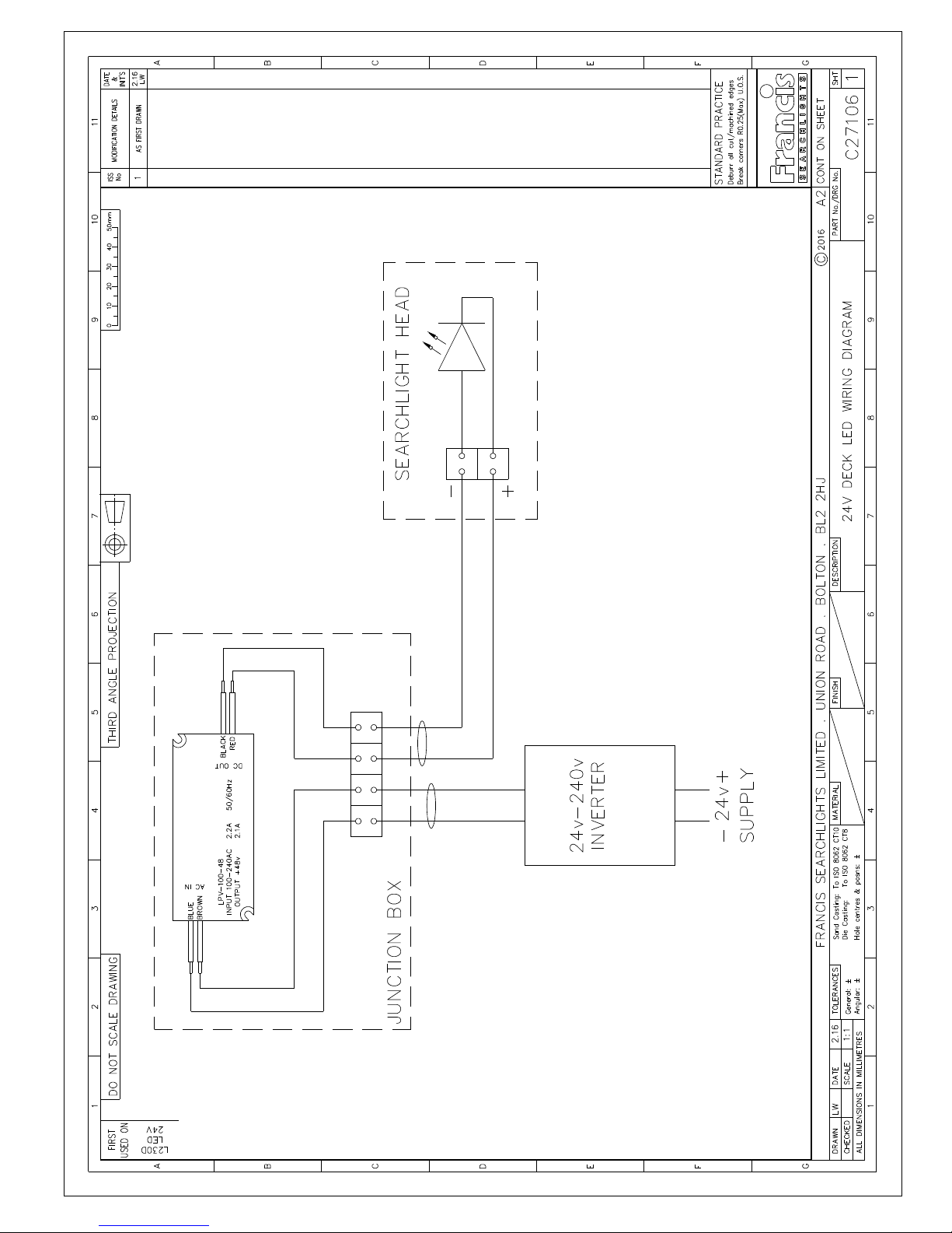
A typical installation and connection routine for the L230 LED 24v searchlight is as follows:
Referring to wiring diagram C27106, a supply is fed to the inverter, which then provides a common
feed to the searchlight.
Cables required to be connected by the customer: -
Supply cable to the inverter and to the junction box.
6 - Operating Instructions
This equipment is designed for use out of doors, in free air. Never place anything on, or cover the
searchlight when in use as this may present a hazard.
The beam of the searchlight cannot be adjusted.
Using the template provided mark out and drill the fixing holes through the deck or cabin roof. In
case of cabin control models, a centre hole is also required to allow the mechanism to pass
through.
On an uneven surface when bolting down the searchlight it is necessary to use a suitable sealant,
such as silicone, in order to ensure weather proofed joint.
This product should not be used for any purpose other than for which it was designed. Any
modifications to the product should not be undertaken without consulting the manufacturer.
7- Fault Finding
All fault finding must be conducted by a competent person or qualified Electrical Engineer.
Failure of LED to light.
In the event of the L.E.D failing to light the following steps should be taken:
1) Check that the mains supply is connected to the input of the LED driver and check all
connections as per the wiring diagram. On operation if the LED does not light, switch off mains
supply and check all fuses;
2) Check output from the LED driver 48 volts no load 36.5 volts with load.

8 - Maintenance and Servicing
In order to prolong the service life and performance of your searchlight, the following maintenance
guidelines are recommended:
Maintenance checks should be conducted before every voyage or at least every three months;
Before checking, disconnect the equipment from the supply;
Visually inspect the condition of the equipment;
Any major or minor structural damage should be rectified immediately in order to reduce
sympathetic wear;
After inspection it may be necessary to clean the inside of the searchlight. The following
procedure should be adhered to:
Remove the front bezel;
Clean the front glass inside and out using a proprietary glass cleaner;
Clean the reflector if required;
It is advisable to check all seals and gaskets for signs of degradation. Renew if necessary;
Upon completing all maintenance requirements the searchlight should be tested for full working
order (approximately 20 minutes).
Every six months the external movement mechanisms i.e. lockwheels, elevation and pan
mechanisms, should be lightly lubricated.
If in any doubt as to the correct servicing procedures to adopt please contact your
distributor/agent or the manufacturer who will be able to advise the best course of action for
your product.

9 - Wiring Diagrams & General Assemblies
Drawing Number Description
A6138/A6144 L230 LED 78w Deck GA
C27105 Wiring Diagram 100-240v
C27106 Wiring Diagram 24v
C27095 Junction Box Assembly


10 – Spare Parts List
The following spare parts can be ordered directly from the manufacturer:
Part Number Description
C22205-01 Handle Assembly
C11025-01 Lock wheel Assembly
C10168-00 Base ‘O’ Ring
C10169-00 Spigot ‘O’ Ring
C22072-00 Push Rod Seal Washer
C21967-00 Bellows Bottom Bush ‘O’ Ring
C26630-00 Front Glass
C21141-00 Front Glass Gasket
C22268-01 Breather Assembly
C27012-00 LED
C27013-00 LED Holder
C27014-00 LED Reflector
C27090-00 LED Driver
C27089-00 24v to 240v Inverter
In order to prolong the life and performance of your product, we recommend that you only specify
Francis Searchlights spare parts. This will ensure that any warranties on your equipment will not be
invalidated.
When ordering spare parts please contact the Sales Department at Francis Searchlights Limited.
Please quote searchlight model and serial number at all times. This will enable a fast response to
your spares’ requirements.
Back To Top
 Loading...