

Fram King 25 Series Operator And Parts Manual
OperatOr and parts Manual
Rotary Tiller
25 Series - 40", 48" & 60"
082010
FK303


Table of Contents - 25 Series Rotary Tiller
Table of Contents
Introduction .................................................................................................................................5
Safety ............................................................................................................................................6
• Safety ................................................................................................................................6
• General Safety ..................................................................................................................7
• Start-up Safety .................................................................................................................7
• Operation Safety ..............................................................................................................7
• Transport Safety ...............................................................................................................7
• Service and Maintenance Safety ....................................................................................8
• Storage Safety ..................................................................................................................8
• Safety Signs .....................................................................................................................8
• Safety Sign Installation ...................................................................................................8
Assembly ....................................................................................................................................10
• Assembly Instructions ...................................................................................................10
Start-up ......................................................................................................................................10
• Machine Break-in ...........................................................................................................10
• Pre-operation Checklist .................................................................................................. 11
Operation ...................................................................................................................................12
• Machine Components ....................................................................................................12
• Equipment Matching .....................................................................................................13
• Driveline Dimension ......................................................................................................14
• Attaching/Unhooking .....................................................................................................15
• Field Operation ...............................................................................................................16
• Transporting ...................................................................................................................19
• Storage ...........................................................................................................................19
• Theory of Operation ......................................................................................................21
Maintenance ..............................................................................................................................22
• Service ............................................................................................................................22
• Fluids and Lubricants ....................................................................................................22
• Greasing .........................................................................................................................22
• Servicing Intervals .........................................................................................................23
• A-frame Adjustment ......................................................................................................24
• Time Replacement .........................................................................................................25
• Shear Bolt .......................................................................................................................25
• Slip Clutch (optional) .....................................................................................................26
3

Table of Contents - 25 Series Rotary Tiller
• Clutch Maintenance .......................................................................................................26
• Troubleshooting .............................................................................................................27
Bolt Torque .................................................................................................................................28
• Checking Bolt Torque .....................................................................................................28
Parts Drawings ...........................................................................................................................29
• Tiller Drawings ...............................................................................................................29
• Tiller Parts List ................................................................................................................31
• PTO (Shear Pin) Drawing ...............................................................................................34
• PTO (Shear Pin) Parts List..............................................................................................35
• PTO (Slip Clutch) Drawing .............................................................................................36
• PTO (Slip Clutch) Parts List ............................................................................................37
• Gearbox Drawing and Parts List ...................................................................................38
Shipping Kit and Bundle Numbers ..........................................................................................39
Warranty .....................................................................................................................................40
Manufacturer’s statement: for technical reasons Buhler Industries Inc. reserves the right to modify
machinery design and specifications provided herein without any preliminary notice.
Information provided herein is of descriptive nature. Performance quality may depend on soil fertility,
applied agricultural techniques, weather conditions and other factors.
4

Introduction - 25 Series Rotary Tiller
Introduction
Farm King has a collection of rotary tiller models to suit your garden and landscaping needs.
The 25 Series Tiller attaches to the 3-point hitch as well as our Cat. 1 Quick Hitch and is designed
to fit a variety of tractors from 12 hp to 25 hp. Tilling widths range from 36" to 54" in the 25 Series.
The tilling shaft is equipped with four to six flanges, depending on the model. Flanges on all
series are available with four tines. This provides an optimum balance between performance and
durability, even in heavy soils and when breaking untilled soil.
Standard on all Farm King Rotary Tillers, the skid shoes are adjustable so it is easy to set the
perfect tilling depth. The automatic chain tightener is standard on all models. This ensures the
chain remains tight even under the toughest tilling conditions. Housing within a sealed oil bath,
the chain tightener is designed to be reliable and maintenance-free. Getting close to the fences,
hedges or covering a tire track is easy with the side shift feature. The entire unit can be pushed to
one side, while the PTO shaft remains in line with the tractor to minimize stress on the universal
joint. The side shift feature is available on all 25 Series Farm King Rotary Tillers.
Keep this manual handy for frequent reference. All new operators or owners must review the
manual before using the equipment and at least annually thereafter. Contact your Farm King
Dealer if you need assistance, information, or additional copies of the manual. Visit our website
at www.buhlerindustries.com for a complete list of dealers in your area.
The directions left, right, front and rear, as mentioned throughout this manual, are as seen facing
in the direction of travel of the implement.
5
Safety - 25 Series Rotary Tiller
Safety
Safety Instructions
Remember, YOU are the key to safety. Good safety practices not only protect you, but also the
people around you. Make these practices a working part of your safety program. Be certain that
everyone operating this equipment is familiar with the recommended operating and maintenance
procedures and follows all the safety precautions. Most accidents can be prevented. Do not risk
injury or death by ignoring good safety practices.
The alert symbol is used throughout this manual. It indicates attention is required and identifies
hazards. Follow the recommended precautions.
The safety alert symbol means…
ATTENTION! BECOME ALERT! YOUR SAFETY IS INVOLVED!
The caution symbol indicates a potentially hazardous situation
CAUTION
that, if not avoided, may result in minor or moderate injury. It
may also be used to alert against unsafe practices.
WARNING
DANGER
The Warning Symbol indicates a potentially hazardous situation
that, if not avoided, could result in death or serious injury, and
includes hazards that are exposed when guards are removed. It
may also be used to alert against unsafe practices.
The Danger Symbol indicates an imminently hazardous situation
that, if not avoided will result in death or serious injury. This
signal word is to be limited to the most extreme situations,
typically for machine components that, for functional purposes,
cannot be guarded.
6

Safety - 25 Series Rotary Tiller
General Safety Instructions
• Have a first-aid kit available for use and know how to use it.
• Have a fire extinguisher available, stored in a highly visible location, and know how to use it.
• Wear appropriate protective gear. This list may include but is not limited to:
- hard hat
- protective shoes with slip resistant soles
- protective glasses or goggles
- heavy gloves
- wet weather gear
- hearing protection
- respirator or filter mask
• Read and understand the Operator’s Manual and all safety signs before operating, servicing,
adjusting, repairing, or unplugging the equipment.
• Do not attempt any unauthorized modifications to your Farm King product as this could
affect function or safety, and could affect the life of the equipment.
• Never start or operate the mower except from the operator’s station on the power unit.
• Inspect and clean the working area before operating.
• Keep hands, feet, clothing, and hair away from moving parts.
• Ensure bystanders are clear of the area before operating.
Start-up Safety
• Do not let inexperienced operators or children run this equipment.
• Place all tractor and machine controls in neutral before starting.
• Operate only with ROPS and seatbelt equipped tractors.
• Do not operate inside a building unless there is adequate ventilation.
• Ensure all shields are in place and in good condition before operating.
• Stay clear of PTO shaft and machine when engaging PTO.
Operation Safety
• Do not permit riders.
• Do not wear loose fitting clothing during operation.
• Never operate over 540 PTO rpm speed.
• Never operate the equipment in the raised position.
Transport Safety
• Review Transport Safety instructions in tractor manual before moving.
• Check with local authorities regarding transport on public roads. Obey all applicable laws
and regulations.
• Make sure the SMV (Slow Moving Vehicle) emblem and all the lights and reflectors that are
required by the local highway and transport authorities are in place, are clean, and can be
seen clearly by all overtaking and oncoming traffic.
• Never have the equipment in operation during transport.
• Always travel at a safe speed.
7
Safety - 25 Series Rotary Tiller
Service and Maintenance Safety
• Stop engine, set brake, remove ignition key, and wait for all moving parts to stop before
servicing, adjusting, repairing, or unplugging.
• Support the equipment with blocks or safety stands before working beneath it.
• Follow good shop practices including:
- keep service area clean and dry
- be sure electrical outlets and tools are properly grounded
- use adequate light for the job.
• Use only tools, jacks, and hoists of sufficient capacity for the job.
• Replace and secure all shields removed during servicing before operating.
• Use heavy leather gloves to handle sharp objects.
Storage Safety
• Store the unit in an area away from human activity.
• Do not permit children to play on or around the stored machine.
• Support the frame on stands and blocks to provide a secure base.
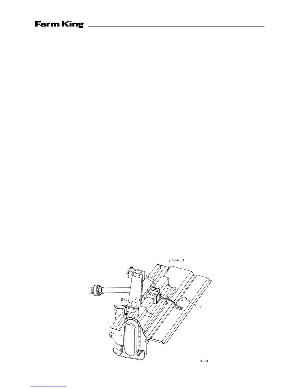
Safety Signs
• The following illustration shows the approximate location and detail of safety signs.
• Keep all safety signs clean and legible and replace any that are damaged or missing.
• When original parts are replaced, any safety signs affixed to those parts should be replaced
as well. Replacement safety signs are available from your local dealer.
Installation
• To install safety signs, ensure the installation area is clean and dry. Decide on the exact
position before you remove the backing paper. Remove the smallest portion of the split
backing paper and align over the specified area. Carefully press in place.
• Slowly peel back the remaining paper and smooth the remaining portion in place. Small air
pockets can be pierced with a pin and smoothed out.
8
Safety - 25 Series Rotary Tiller
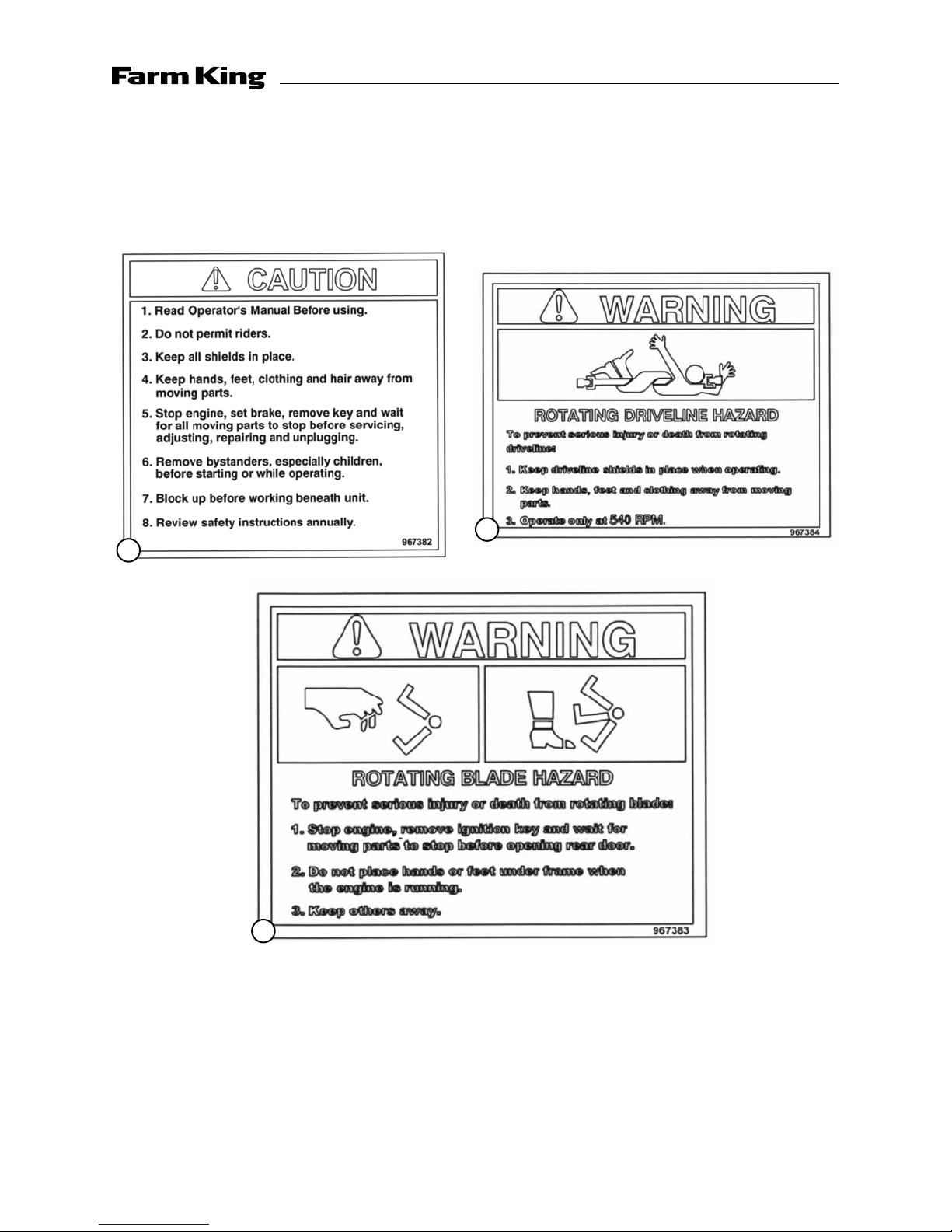
• Replace safety signs immediately should they become damaged, torn or illegible.
Obtain replacements from your authorized dealer using the part numbers shown.
B
A
C
9

Assembly / Start-up - 25 Series Rotary Tiller
Assembly Instructions
The machine is shipped with the PTO shaft not installed.
To install the PTO driveline on the machine, follow this procedure.
1. Clear the area of bystanders, especially small children.
2. Clean the splines on the yoke and the input shaft.
3. Align the splines on the yoke and the shaft.
4. Attach the driveline to the tiller by removing the tapered pin and sliding the yoke onto the
gearbox shaft. Line up the pin with the groove in the gearbox shaft and fasten with the tapered
pin. The plastic gearbox PTO guard has a removable door on top to access the pin. The A-frame
brace can be removed to improve accessibility. Replace the brace after tightening the nut on
the tapered pin.
5. Be sure the yoke is locked in position. Pull on the yoke to be sure the pin clicks into position.
6. Be sure that the PTO shaft is the appropriate length for the tractor/Tiller combination. Refer to
Driveline Dimension Section for details.
Start-up
Machine Break-in
Although there are no operational restrictions on the Tiller when used for the first time, it is
recommended that the following mechanical items be checked:
• After operating for 1/2 hour or after completing 1/2 acre:
- Check all nuts, bolts and other fasteners. Tighten to their specified torque level.
- Check that the blades are in good condition and bolted securely to the rotor.
- Check the oil level in the gearbox. Add as required.
- Check that the PTO driveline shield turns freely.
- Lubricate all grease points.
• After operating for 5 hours and 10 hours:
- Repeat the items above.
- Then go to the regular service schedule as defined in Section 5.
10

Start-up - 25 Series Rotary Tiller
Pre-operation Checklist
Efficient and safe operation of the Rotary Tiller requires that each operator reads and understands
the operating procedures and all related safety precautions outlined in this section. A pre-operation
checklist is provided for the operator. It is important for both personal safety and maintaining the
good mechanical condition of the Tiller that this checklist is followed.
• Before operating the machine and each time thereafter, the following areas should be checked
off:
□ Lubricate the machine per the schedule outlined in the Service and Maintenance Section.
□ Use only a tractor of adequate power and weight to pull the machine.
□ Check that the machine is properly attached to the tractor. Be sure retainers are used on the
mounting pins.
□ Check the oil level in the gearbox. Add as required.
□ Check that the PTO driveline shield turns freely and that the driveline can telescope easily.
Clean and lubricate if required.
□ Check the blades. Be sure they are not damaged or broken and are bolted securely to the
rotor. Repair or replace as required.
□ Remove any entangled material on rotating parts.
□ Install and secure all guards, doors and covers before starting.
□ The four socket set screws on the inside of the PTO clutch assembly must be turned out as far
as they go to engage the clutch.
11
Operation - 25 Series Rotary Tiller
Operation Instructions
The Farm King 25 Series Rotary Tiller is a machine that combines the primary and secondary tillage
operation into one machine. It breaks up the soil and prepares the seed bed in one pass. Rotational
power to the rotor is provided by the tractor PTO. Be familiar with the machine before starting.
NOTE: It is the responsibility of the owner or operator to read this manual and to train all other
operators before they start working with the machine. Follow all safety instructions exactly. Safety
is everyone's business. By following recommended procedures, a safe working environment is
provided for the operator, bystanders and the area around the work site. Untrained operators are
not qualified to operate the machine.
Many features incorporated into this machine are the result of suggestions made by customers
like you. Read this manual carefully to learn how to operate the machine safely and how to set it
to provide maximum field efficiency. By following the operating instructions in conjunction with a
good maintenance program, your Tiller will provide many years of trouble free service.
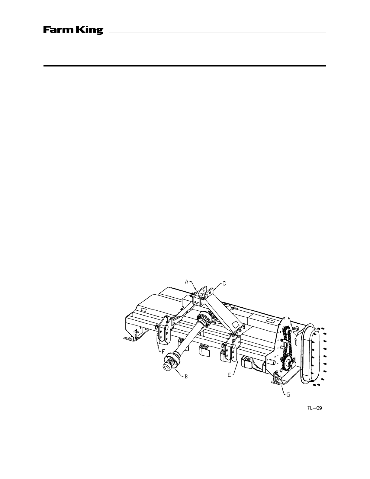
Machine Components
The Farm King 25 Series Rotary Tiller consists of a rotating drum that is equipped with bent blades
for breaking up and leveling soil. The blades are turned through the soil while the machine moves
over the working area. A Drag Shield is used to maintain a level seedbed. Rotational power to the
drum is provided by the PTO on the tractor. The power is transmitted through the gearbox in the
center of the machine to the chain drive down the side. The A-frame can be moved to offset the
machine.
A - Point A-frame
B - PTO Driveline
C - Gear Box
D - Chain Drive
E - Rotor
F - Blades
G - Skid Plates
12
Operation - 25 Series Rotary Tiller
Equipment Matching
To insure the safe and reliable operation of the Tiller, it is necessary to use a tractor with the correct
specifications. Use the following list as a guide in selecting a tractor to use on the machine.
1. Horsepower: Use Table 1 as a guide in selecting the tractor horsepower appropriate for your
width of machine. Use only small Agricultural tractors on this machine.
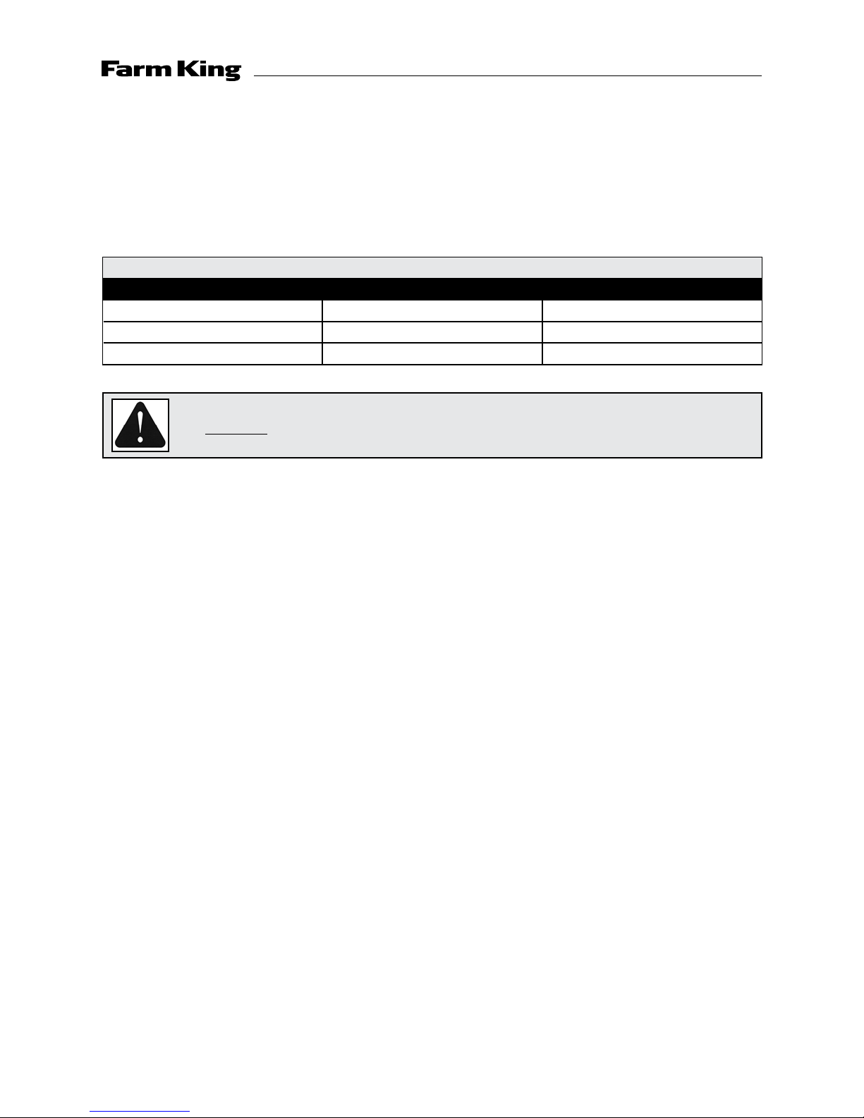
Table 1 - Horsepower vs. Width
Model Width Horsepower
40S 3.3 ft (1.0 m) 18
48S 4 ft (1.3 m) 22
60S 5 ft (1.5 m) 25
ALERT
2. 3- Point Hitch: The Tiller is equipped with a Category 1, 3-point hitch. Be sure the tractor
3-point hitch is in the Category 1 configuration. Install the lift arm blocks or shorten the stop
chains to place the arms into the non-sway configuration. Refer to the tractor manual for
details.
3. Load Sensing Hydraulics: Many newer tractors are equipped with “Load Sensing” hydraulics.
It is the responsibility of the operator to set the tractor hydraulic system to provide “float” on
the 3-point hitch. The float feature will allow the machine to follow the ground contours during
operation.
4. PTO Shaft: The tractor must have a 1-3/8" 6 spline 540 rpm PTO shaft to fit the driveline shaft
supplied with the machine. Do not use shaft adapters or operate at any other speed. It is
not recommended that a tractor with variable speed PTO’s be used on the Tiller. Operating at
speeds faster than 540 rpm will overload the drivetrain and lead to early failures.
Attach the safety chains supplied with the PTO shaft, allowing sufficient slack for the driveline
during turns and operation. Check booklet attached to the PTO for instructions.
Do not exceed the recommended horsepower levels. The use of
horsepower will void the warranty.
13
Operation - 25 Series Rotary Tiller
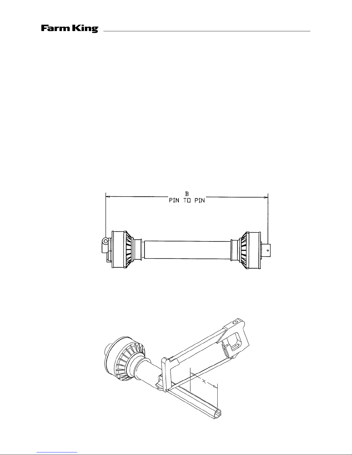
Driveline Dimension
A PTO driveline is supplied with the machine. To accommodate the variety of 3-point hitch
geometry available today, the driveline can be too long for some machines and must be cut.
It is very important that the driveline be free to telescope but not bottom out when going through
its working range. If the driveline bottoms out, the bearings on both the machine and tractor PTO
shaft will be overloaded and fail in a short time.
If cutting the drive is necessary, follow this procedure:
1. Clear the area of bystanders, especially small children.
2. Attach the Tiller to the tractor but do not attach the driveline.
3. Raise the machine until the input gearbox shaft is level with the Tractor PTO shaft.
4. Measure the dimension between the locking groove on the tractor PTO shaft and the groove
on the Tiller input shaft.
5. Measure the same dimensions on the compressed driveline.
6. If the driveline pin to pin dimension (B) exceeds the groove to groove dimension, the driveline
should be cut.
7. Pull the driveline apart and cut 1/2 of the dimension determined in step 5 from each end. Add
another 1/2" (12mm) to each cut off segment.
14
 Loading...