

Framery 2Q Installation Instructions Manual
Framery 2Q
English
Installation Instructions
Version 1.0


Contents
1 Safety.................................................................................................................5
2 Installation requirements................................................................................ 7
2.1 Tools and accessories.................................................................................................7
2.2 Main dimensions..........................................................................................................8
2.3 Installation space.........................................................................................................9
2.4 Operating space.......................................................................................................... 9
3 Install the backside module..........................................................................11
3.1 Install the floor module of the backside module....................................................... 11
3.2 Install the roof module of the backside module........................................................ 15
3.2.1 Join the roof modules (back)........................................................................ 15
3.2.2 Fix the roof modules together (back)............................................................ 17
3.2.3 Install the top center frame piece (back).......................................................19
3.3 Install the roof and wall modules of the backside module........................................ 21
3.3.1 Fix the support beam to the wall modules (back)......................................... 21
3.3.2 Assemble the roof support beams (back)..................................................... 22
3.3.3 Fix the roof modules to the wall modules (back).......................................... 23
3.3.4 Fix the combined roof and wall module to the floor modules (back)............. 27
3.4 Check module straightness....................................................................................... 29
4 Install the frontside module..........................................................................35
4.1 Install the floor module of the frontside module........................................................35
4.2 Install the roof module of the frontside module.........................................................38
4.2.1 Join the roof modules (front).........................................................................38
4.2.2 Fix the roof modules together (front)............................................................ 40
4.3 Install the roof and wall modules of the frontside module.........................................43
4.3.1 Fix the support beam to the wall modules (front)..........................................43
4.3.2 Fix the roof modules to the wall modules (front)...........................................45
4.3.3 Fix the combined roof and wall module to the floor modules (front)..............48
5 Connect the backside and frontside modules............................................ 50
5.1 Check module straightness after connecting the modules........................................53
6 Install the backside frames and glasses..................................................... 60
6.1 Install the left-hand side frames................................................................................60
6.2 Install the first and center glasses............................................................................ 63
6.3 Install the right-hand side frames and the second glass...........................................66
6.4 Finalize the installation of the backside frames and glasses.................................... 70

7 Install the frontside frames and glasses..................................................... 72
7.1 Install the corner and side frames............................................................................ 72
7.2 Install the side glasses.............................................................................................. 75
7.3 Finalize the installation of the frontside frames and glasses.....................................78
8 Install the door............................................................................................... 81
8.1 Prepare the door installation..................................................................................... 81
8.2 Install the door...........................................................................................................83
8.3 Install the door handles............................................................................................. 87
8.4 Adjust the door height...............................................................................................89
8.5 Adjust the closing speed of the door........................................................................ 91
8.6 Adjust the automatic door seal................................................................................. 93
9 Install the table and electrics....................................................................... 94
9.1 Install the motion detector......................................................................................... 94
9.2 Install the seal and the metal sheets........................................................................96
9.3 Install the back profile of the power column............................................................. 97
9.4 Install the front profile of the power column............................................................100
9.5 Install the electrical connections............................................................................. 106
9.6 Install the table (optional)........................................................................................111
9.7 Install the display (optional).................................................................................... 113
9.8 Install the roof cover panels....................................................................................115
9.9 Install the lamps...................................................................................................... 117
10 Install the cover panels and the body covers.........................................119
10.1 Install the roof cover plates...................................................................................119
10.2 Install the wall cover panels..................................................................................120
10.3 Install the bottom body covers.............................................................................. 122
10.4 Install the wall body covers...................................................................................123
10.5 Install the roof body covers...................................................................................124
10.6 Finalize the installation of the body covers........................................................... 127
1 Safety
This chapter outlines important safety matters concerning the installation and maintenance of
the pod. It is important that these instructions are followed to recognize and prevent potential
risks before they occur.
Note: All personnel must understand and observe these instructions prior to
installation or maintenance of the pod.
Restrictions
• Non-conventional use
• Installation or maintenance of the pod without reading and understanding the instructions
• Use of the pod beyond the limits of use
• Making alterations to the pod
• Using the pod in spite of obvious defects or damage
• Using the pod outdoors
Making alterations to the pod
Warning: To prevent risks and ensure optimal performance, rebuilding or making any
alterations to the pod may not be carried out without the manufacturer’s explicit prior
permission.
Safety considerations
Note: Read these instructions before installation or maintenance.
Note: Use safety boots and cut-resistant gloves during installation and maintenance.
Note: The use of the pod is only permitted after it has been properly installed.
Note: When installing or performing maintenance, follow all the local requirements for
safety issues, lifting, and other special tasks.
Note: Keep the installation or maintenance area clean.
Note: After installation or maintenance, clean up the surroundings of the pod.
Note: Do not cover the ventilation channels.
Note: Never drop or insert any object into any opening unless instructed.
Note: Do not place heavy objects on the floor or roof of the pod.
Note: Do not attach or hang extra weight from the door.
Warning: Always unplug the pod from the electrical outlet before performing any
maintenance. To disconnect, remove plug from outlet.
Framery 2Q Installation Instructions
info@frameryacoustics.com
5

Installation environment
The pod is intended to be used in the following conditions.
• Ambient temperature: +15°C ... +30°C (59°F ... 86°F)
• Humidity: max. 50%
6
Framery 2Q Installation Instructions
info@frameryacoustics.com
2 Installation requirements
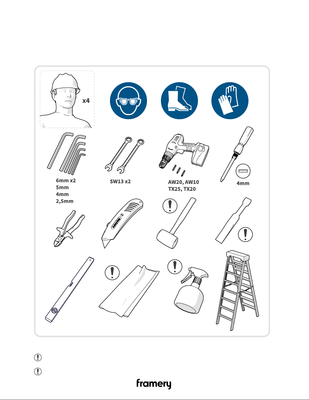
2.1 Tools and accessories
Figure 1: Tools and accessories needed for installation and maintenance
Note: Use a white rubber mallet to not leave marks on the body covers.
Note: Use a plastic chisel.
Framery 2Q Installation Instructions
info@frameryacoustics.com
7
Note: Use a mat in the door installation.
Tip: You can use glass washing liquid as a lubricant to help with the installation of the
seal.
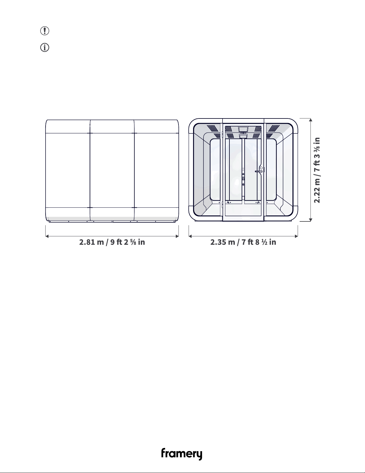
2.2 Main dimensions
Figure 2: Main dimensions of the 2Q pod
8
Framery 2Q Installation Instructions
info@frameryacoustics.com
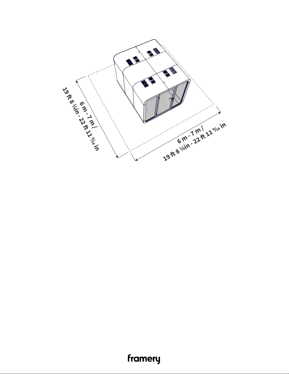
2.3 Installation space
Figure 3: Installation space measurements
2.4 Operating space
When in use, the pod needs an area of 2.45 m (8 ft 7/16 in) X 3.7 m (12 ft 1 11/16 in) X 2.42 m
(7 ft 11 5/16 in). The dimensions for 2Q include the minimum recommended space for the air
to circulate: 200 mm (7 7/8 in) above the pod and 50 mm (1 15/16 in) around the pod.
Framery 2Q Installation Instructions
info@frameryacoustics.com
9
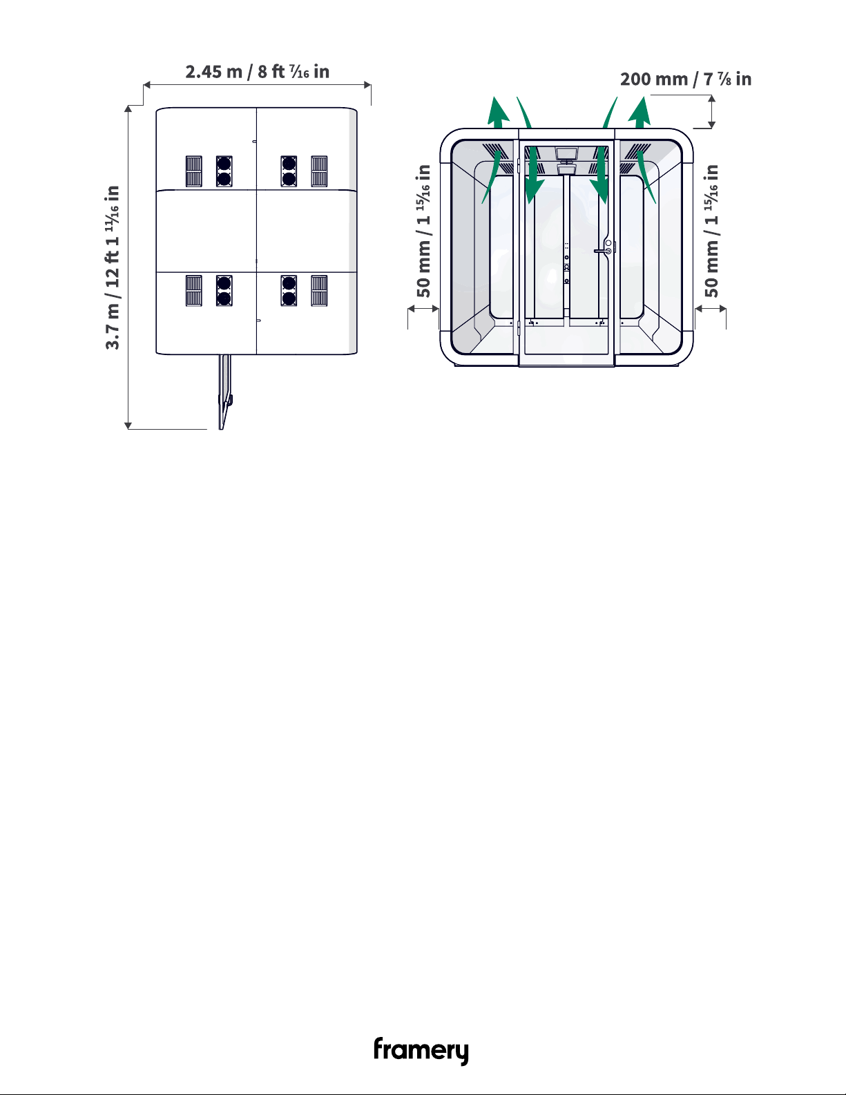
Figure 4: Operating space measurements
10
Framery 2Q Installation Instructions
info@frameryacoustics.com

3 Install the backside module
3.1 Install the floor module of the backside module
1. Press wooden pins (4 pcs) into the holes in the backside I-beam.
2. Stand two corner pieces on their wide ends.
Note: Support the pieces at all times. Make sure that the nut in the I-beam faces
the inside of the module.
3. Join the wooden pins into the holes in the corner pieces.
Framery 2Q Installation Instructions
info@frameryacoustics.com
11

4. Press wooden pins (14 pcs) into the corner pieces.
5. Press the floor board onto the corner pieces.
Note: Make sure that the narrow end of the floor module is at the open end of the
module.
12
Framery 2Q Installation Instructions
info@frameryacoustics.com

6. Install 5x30 screws (18 pcs).
Note: Install the screws from the middle of the floor module to the ends. Make
sure that the pins are in place.
Note: Make sure that the screw heads are level with the floor or deeper.
7. Lay down the floor module.
8. Install guide pins (4 pcs) to the installation holes.
There are two guide pins for each floor corner piece.
Framery 2Q Installation Instructions
info@frameryacoustics.com
13
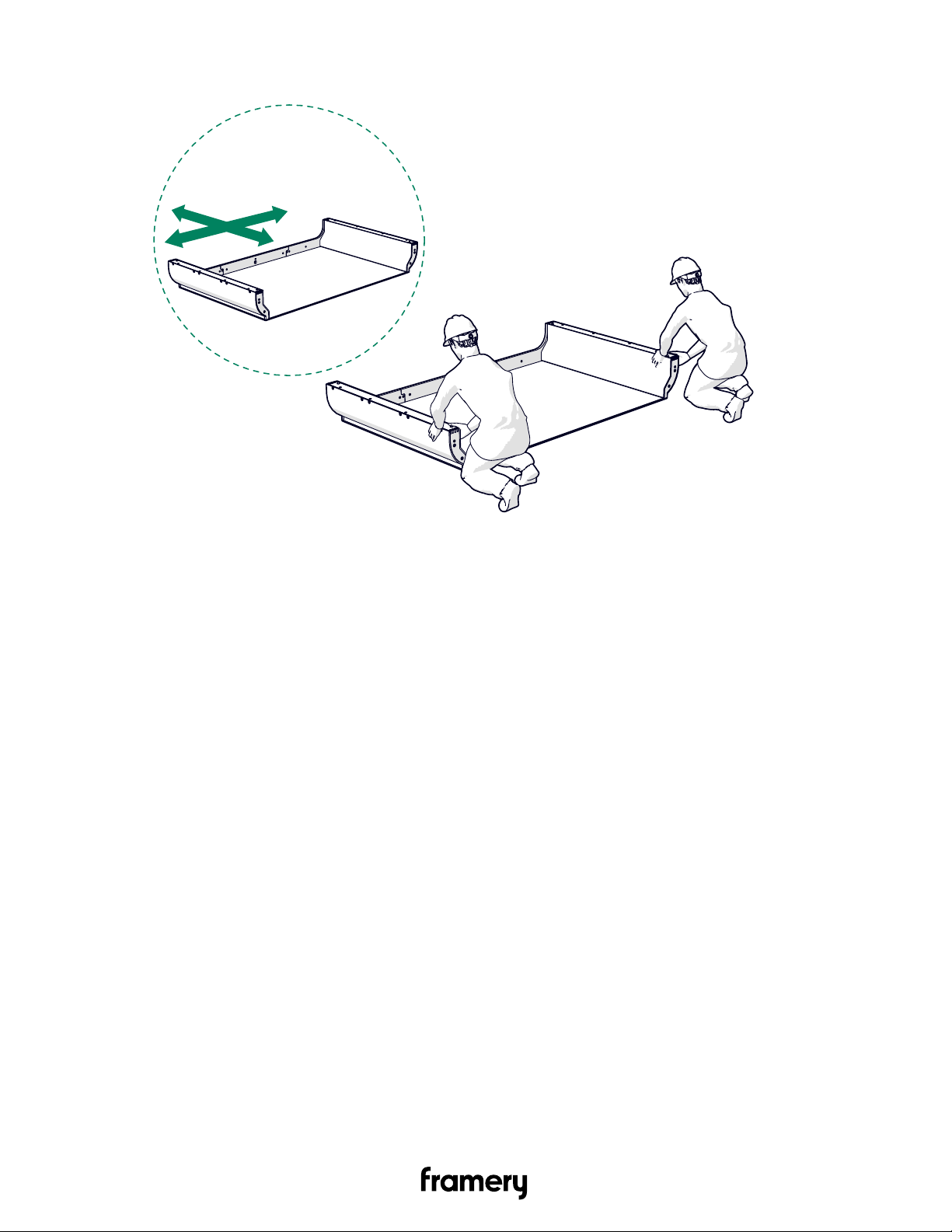
9. Position the backside module at the intended final location.
14
Framery 2Q Installation Instructions
info@frameryacoustics.com
3.2 Install the roof module of the backside module
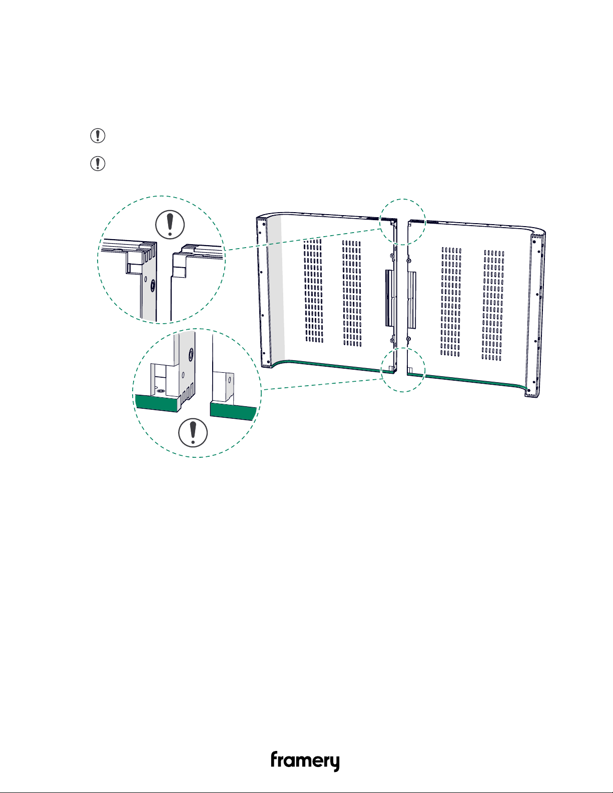
3.2.1 Join the roof modules (back)
1. Stand the roof modules on their sides.
Note: Make sure that the black ABS strips are against the ground.
Note: Make sure that you join the correct roof module pair. The two backside roof
modules have square holes in two corners of the ceiling felt.
Framery 2Q Installation Instructions
info@frameryacoustics.com
15
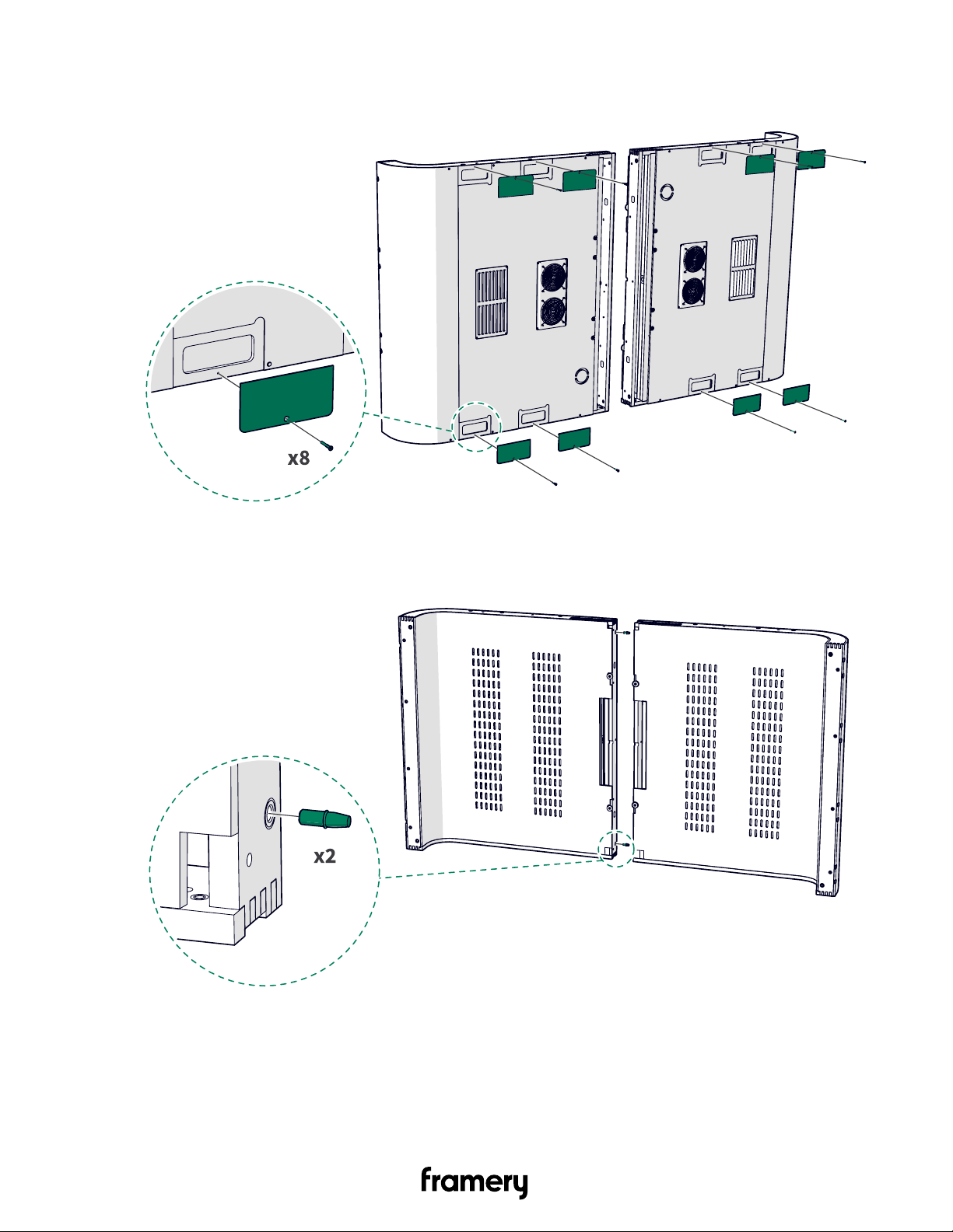
2. Unscrew the 4x30 screws (8 pcs) and remove the cover plates (8 pcs). Set the cover
plates and screws aside.
3. Install guide pins (2 pcs) into the installation holes.
16
Framery 2Q Installation Instructions
info@frameryacoustics.com
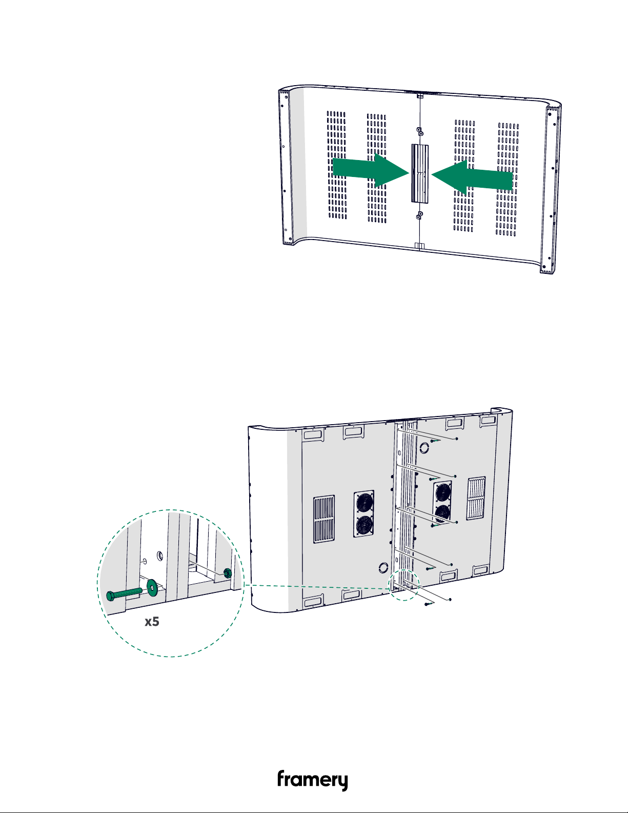
4. Join the roof modules together.
3.2.2 Fix the roof modules together (back)
1. Install M8x55 bolts (5 pcs), M8 washers (5 pcs), and M8 nuts (5 pcs).
Framery 2Q Installation Instructions
info@frameryacoustics.com
17
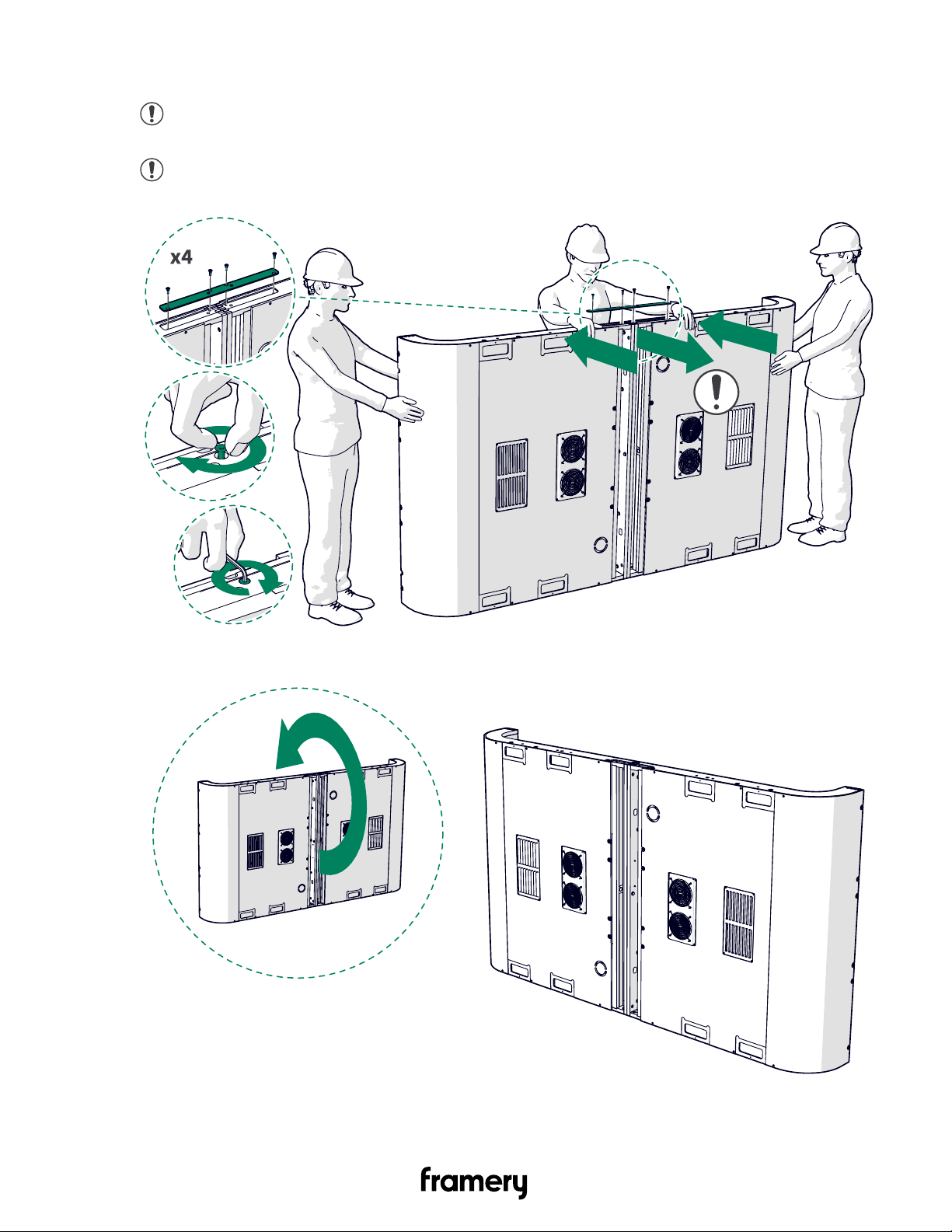
2. Install the support plate with steel colored M6x20 screws (4 pcs).
Note: Pull the roof modules straight to fit the support plate in place. Tighten the
screws by hand and bend the modules further, if needed.
Note: Use a hex key to fully tighten the screws. Make sure that the screws are
properly tightened.
3. Lay down the joined module and lift it up to stand on the other side.
18
Framery 2Q Installation Instructions
info@frameryacoustics.com
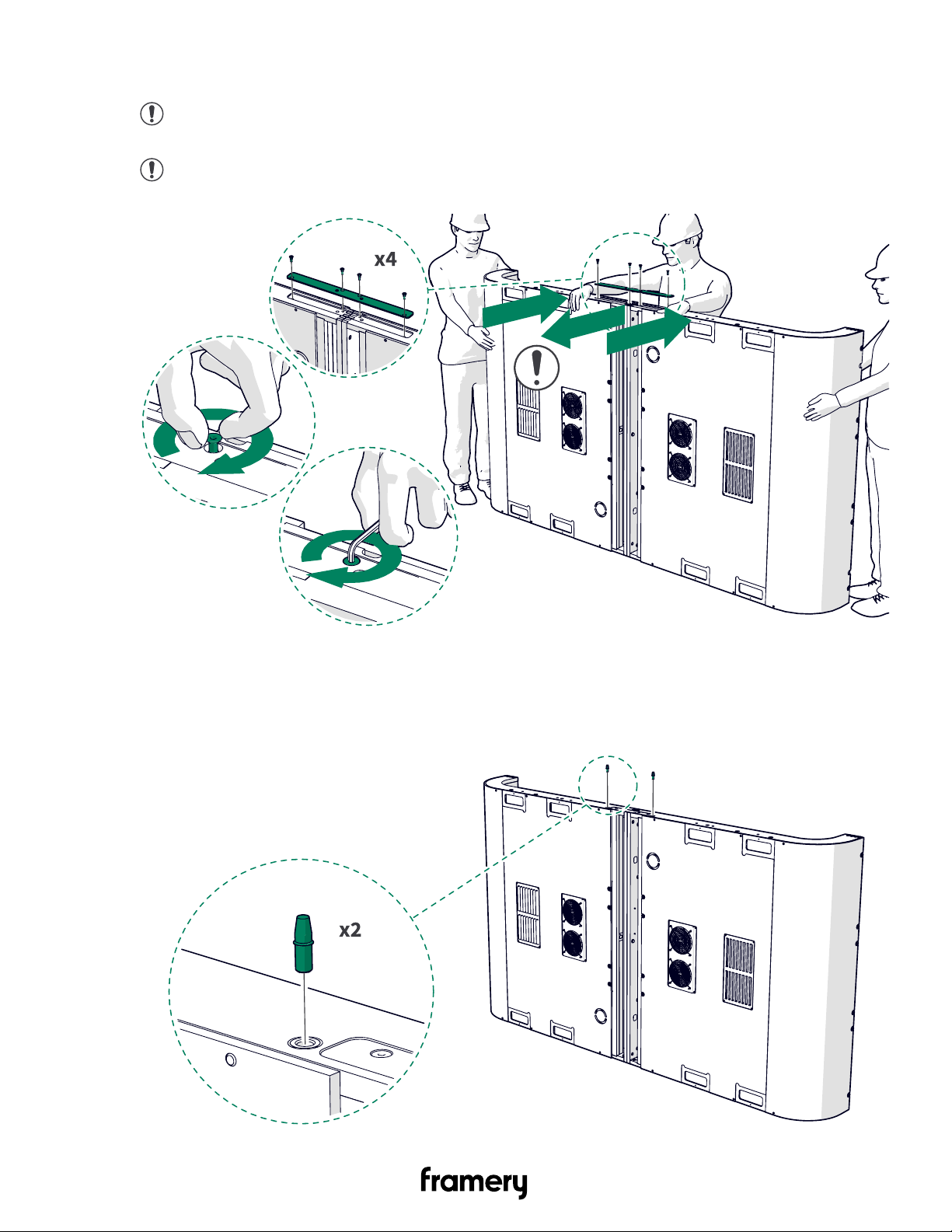
4. Install the other support plate with steel colored M6x20 screws (4 pcs).
Note: Pull the roof modules straight to fit the support plate in place. Tighten the
screws by hand and bend the modules further, if needed.
Note: Use a hex key to fully tighten the screws. Make sure that the screws are
properly tightened.
3.2.3 Install the top center frame piece (back)
1. Install guide pins (2 pcs) into the installation holes.
Framery 2Q Installation Instructions
info@frameryacoustics.com
19
2. Install the top center frame piece with M8x55 bolts (3 pcs) and M8 washers (3 pcs).
Note: Press the acoustic panel aside to reach the bolt holes. Make sure that the
acoustic panel returns to the original position.
Note: To make installation easier, push the modules in the middle when you install
the frame piece.
20
Framery 2Q Installation Instructions
info@frameryacoustics.com
3.3 Install the roof and wall modules of the backside module
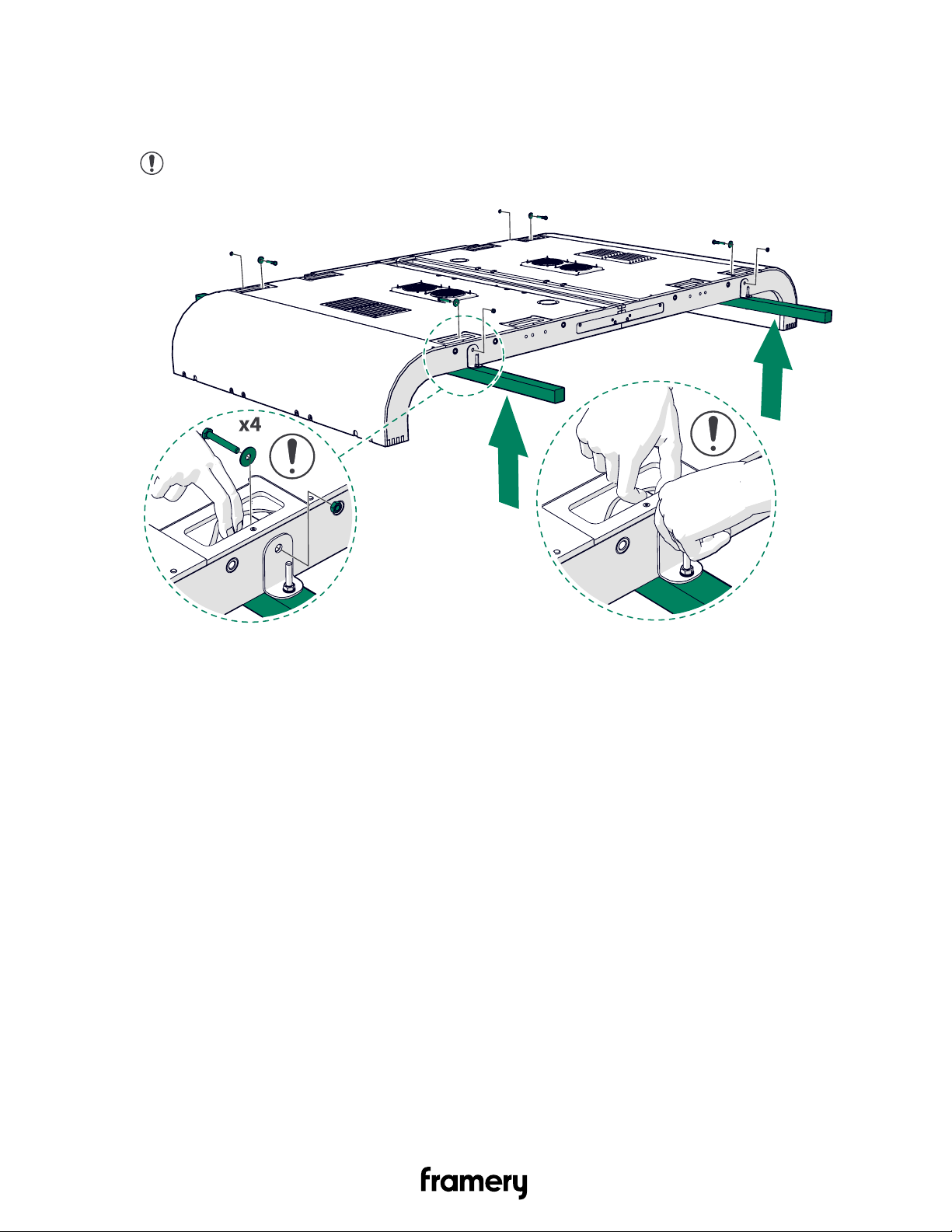
3.3.1 Fix the support beam to the wall modules (back)
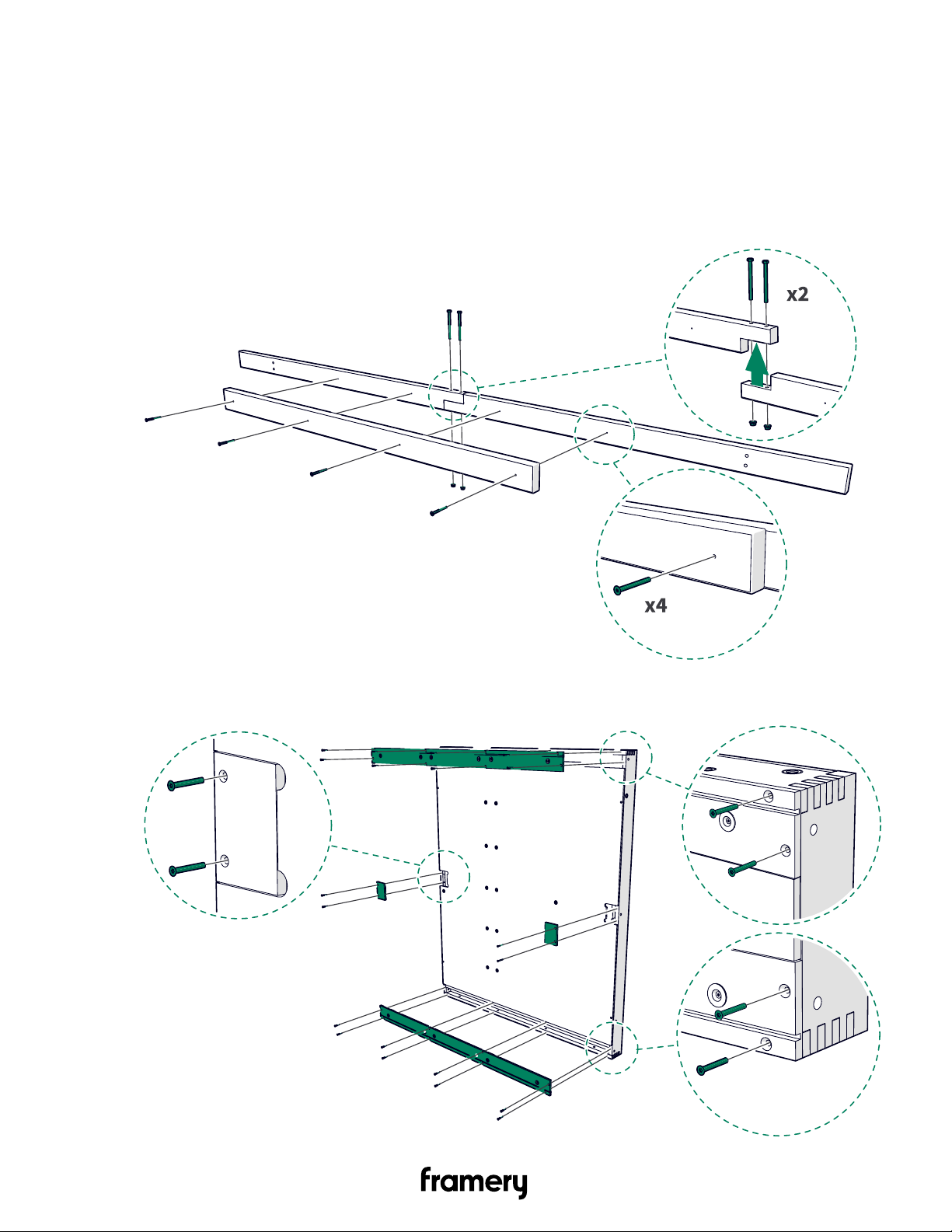
1. Install two support beam pieces together with M8x90 bolts (2 pcs) and M8 nuts (2 pcs).
Install the extra support with 5x50 bolts (4 pcs) in the middle of the support beams.
Assemble two support beams.
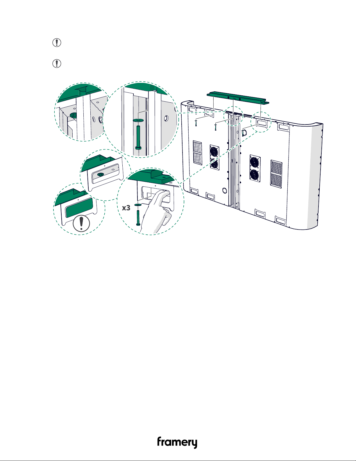
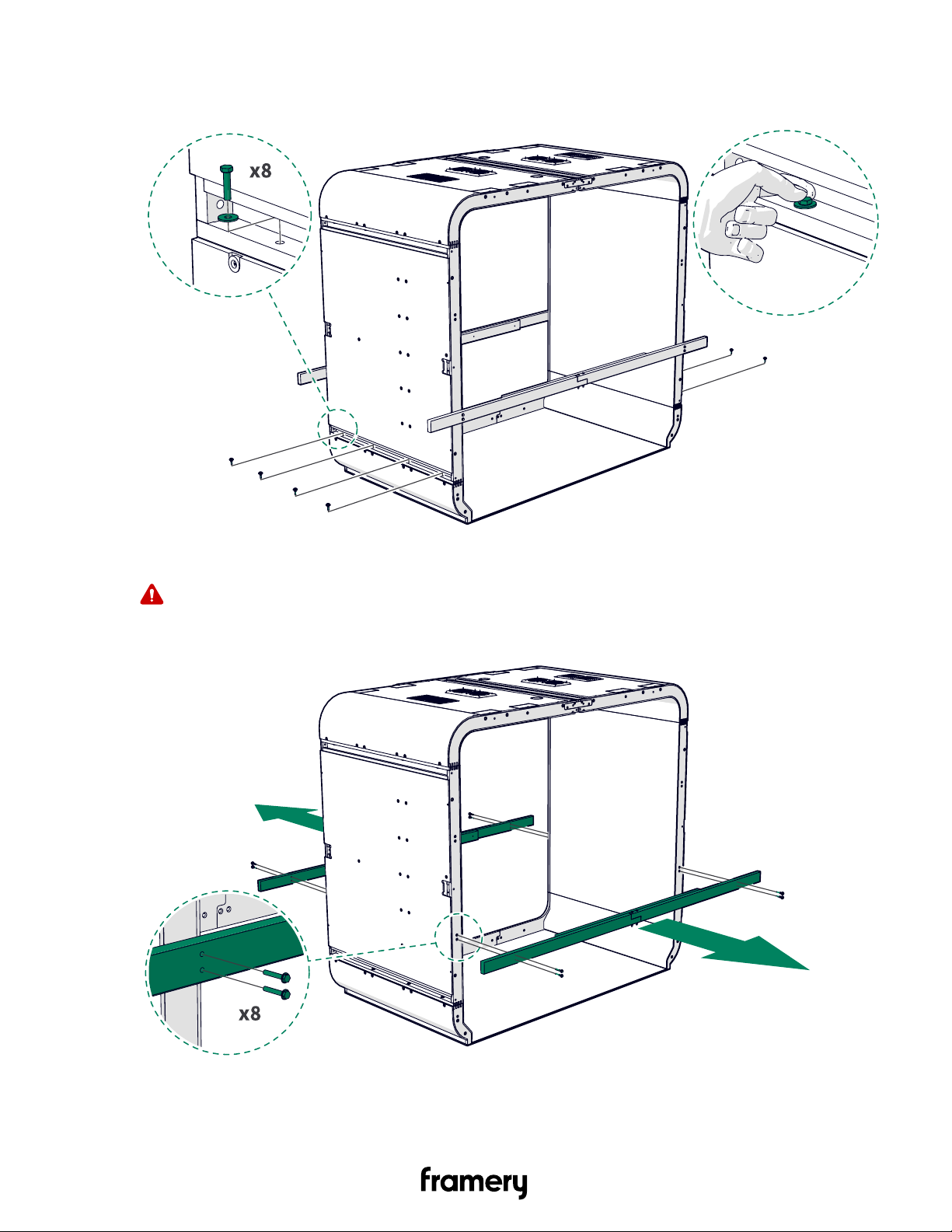
2. Unscrew the 4x30 screws (20 pcs) and remove the cover panels (8 pcs). Set the cover
panels and screws aside.
Framery 2Q Installation Instructions
info@frameryacoustics.com
21
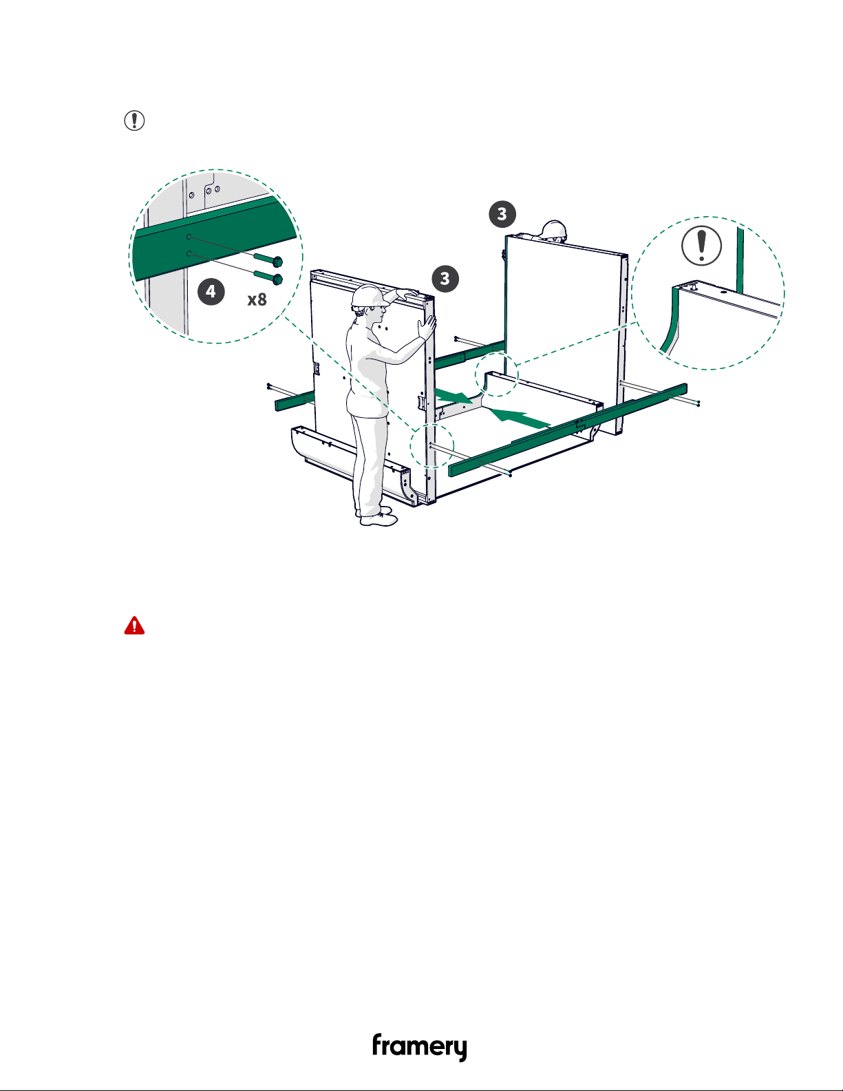
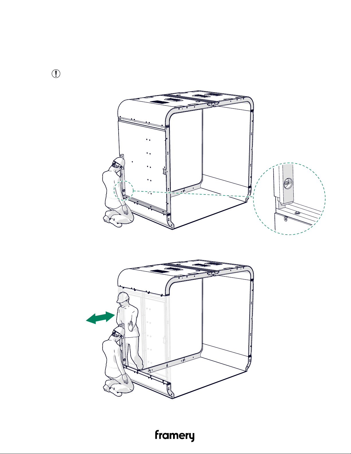
3. Stand one of the wall modules on the floor board and the other on the outside of the floor
module.
Note: Make sure that the black ABS strips are on the outer sides of the wall
modules.
4. Install one support beam on each side of the wall modules with flanged M8x50 bolts (4
pcs).
The support beams extend past the sides of the wall modules.
Warning: Support the walls continuously until the support beams are installed.
3.3.2 Assemble the roof support beams (back)
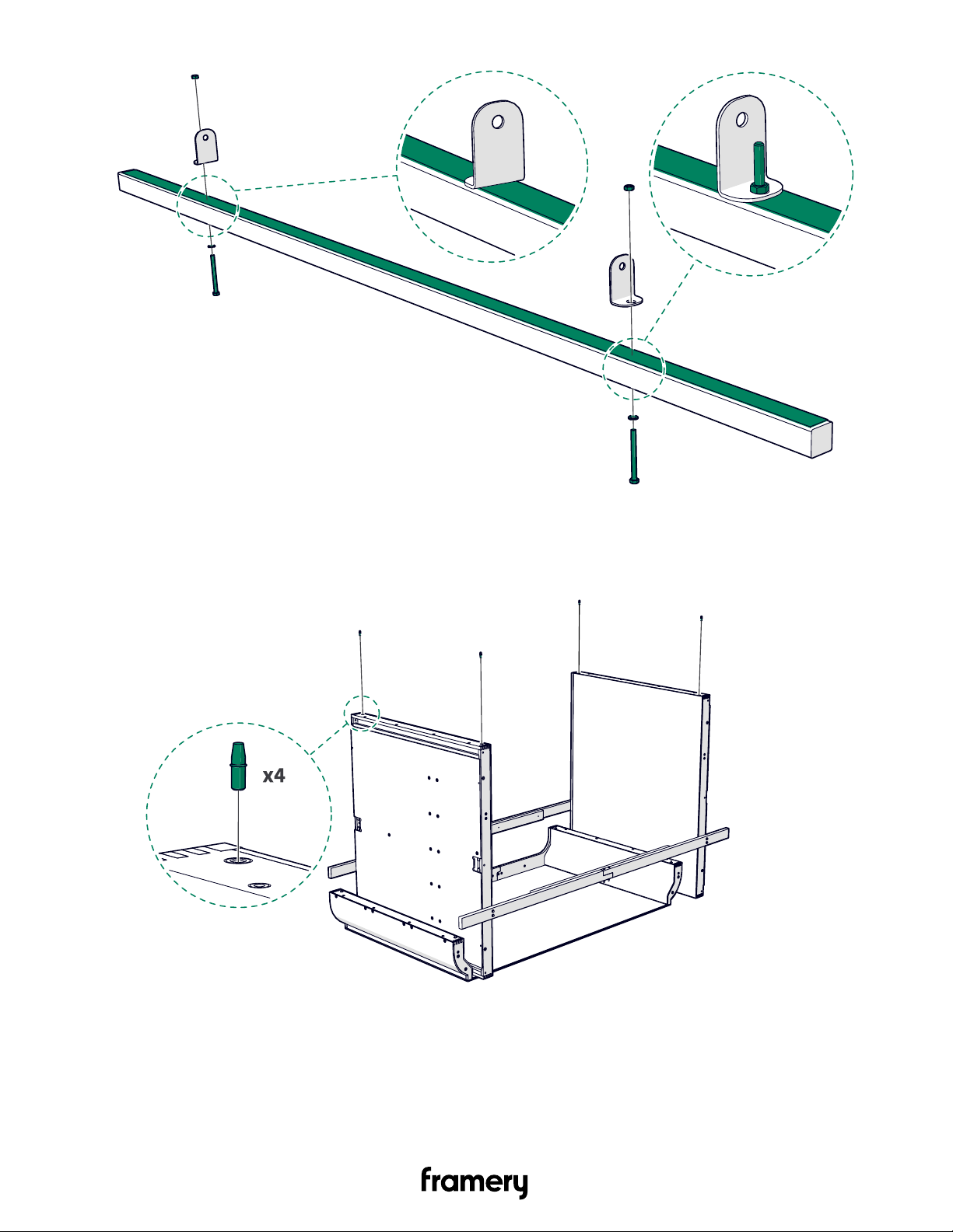
Install the angle irons to the roof support beams with M8x90 bolts (2 pcs), M8 washers (2 pcs)
and M8 nuts (2 pcs).
Place the angle irons on top of the blue foam covering.
22
Framery 2Q Installation Instructions
info@frameryacoustics.com
3.3.3 Fix the roof modules to the wall modules (back)
1. Install guide pins (4 pcs) to the installation holes at the top of the wall modules.
Framery 2Q Installation Instructions
info@frameryacoustics.com
23
2. Install the roof support beams to the roof with M8x55 bolts (2 pcs each) and M8 nuts (2
pcs each).
Place the blue foam covering against the ceiling felt.
Note: Install the bolt on the inside and the nut on the outside. Tighten the bolts by
hand.
24
Framery 2Q Installation Instructions
info@frameryacoustics.com
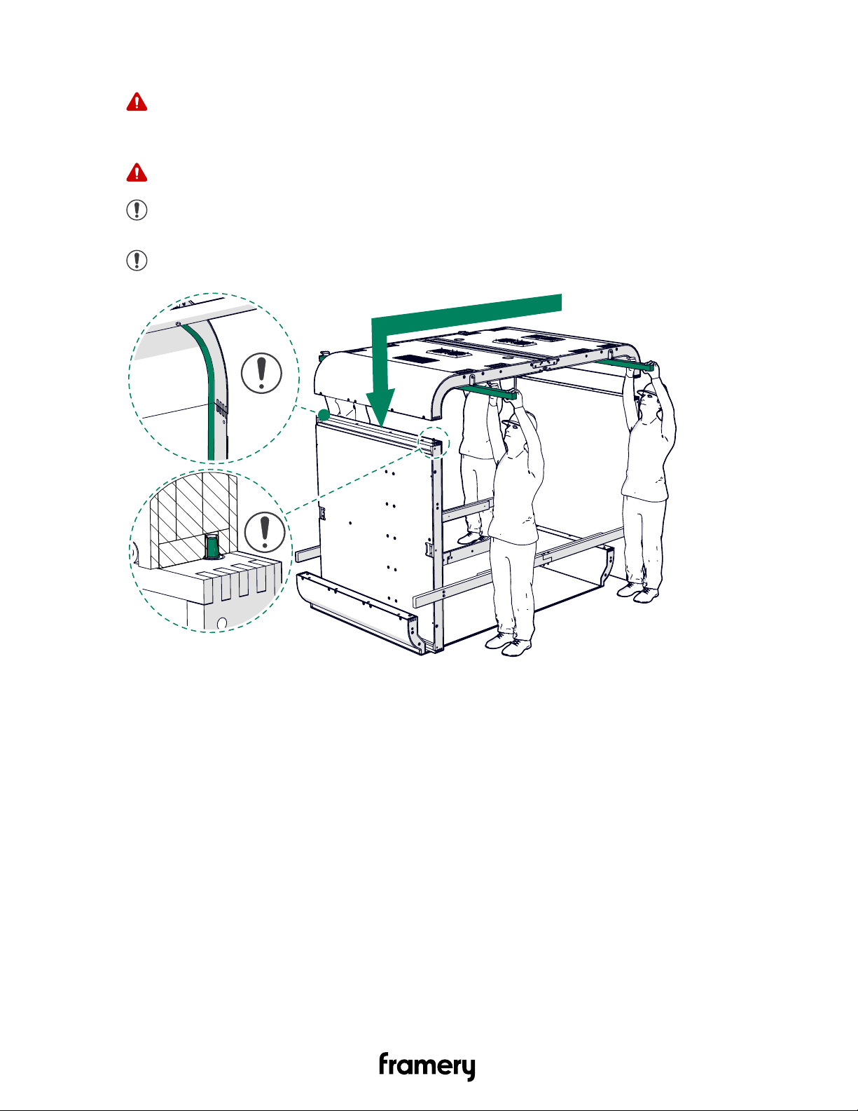
3. Lift the roof module pair carefully into place.
Warning: Heavy object, risk of injury! Follow the regulations for safe lifting. Lifting
requires four persons. Do not go under the roof module until the fixing bolts are
installed.
Warning: Keep the installation area clear of obstacles that you may stumble over.
Note: Make sure that the ABS strips meet at the outer sides of the roof and wall
modules.
Note: Make sure that the guide pin meets the installation hole in the roof module.
Framery 2Q Installation Instructions
info@frameryacoustics.com
25
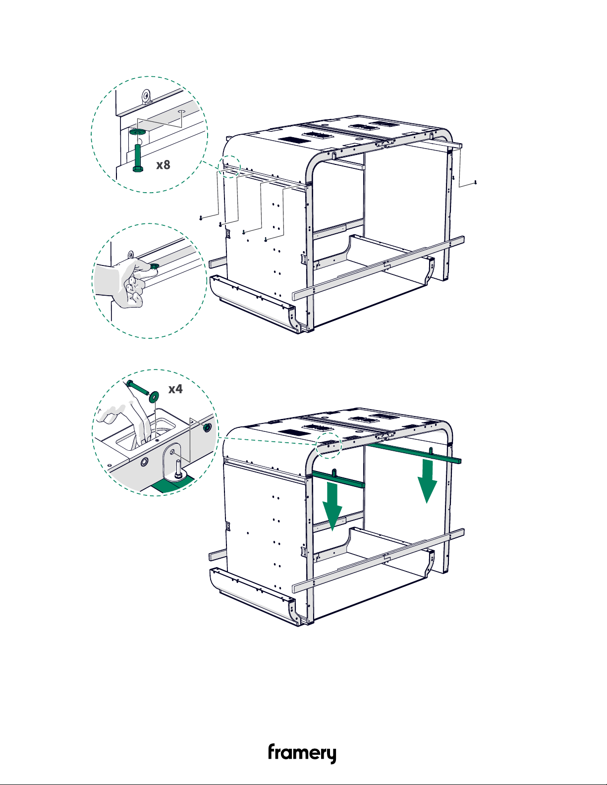
4. Install M8x35 bolts (4 pcs each side) and M8 washers (4 pcs each side). Tighten the bolts
by hand.
5. Remove the roof support beams and keep them for later use.
26
Framery 2Q Installation Instructions
info@frameryacoustics.com
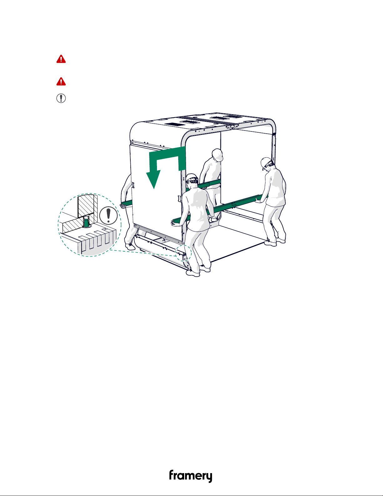
3.3.4 Fix the combined roof and wall module to the floor modules (back)
1. Lift the combined roof and wall module into place.
Warning: Heavy object, risk of injury! Follow the regulations for safe lifting and
pay attention to your posture. Lifting requires four persons.
Warning: Keep the installation area clear of obstacles that you may stumble over.
Note: Make sure that the guide pin meets the installation hole in the roof module.
Framery 2Q Installation Instructions
info@frameryacoustics.com
27
2. Install M8x35 bolts (4 pcs each side) and M8 washers (4 pcs each side). Tighten the bolts
by hand.
3. Remove the support beams and store them for later use.
Warning: Do not go inside the module after removing the support beams before
you tighten the bolts.
28
Framery 2Q Installation Instructions
info@frameryacoustics.com
3.4 Check module straightness
1. Check the straightness of the lower left side with a spirit level slightly above the floor and
wall module junction.
Note: Check straightness from the back part of the module.
2. Push the module as needed and hold straight.
Framery 2Q Installation Instructions
info@frameryacoustics.com
29
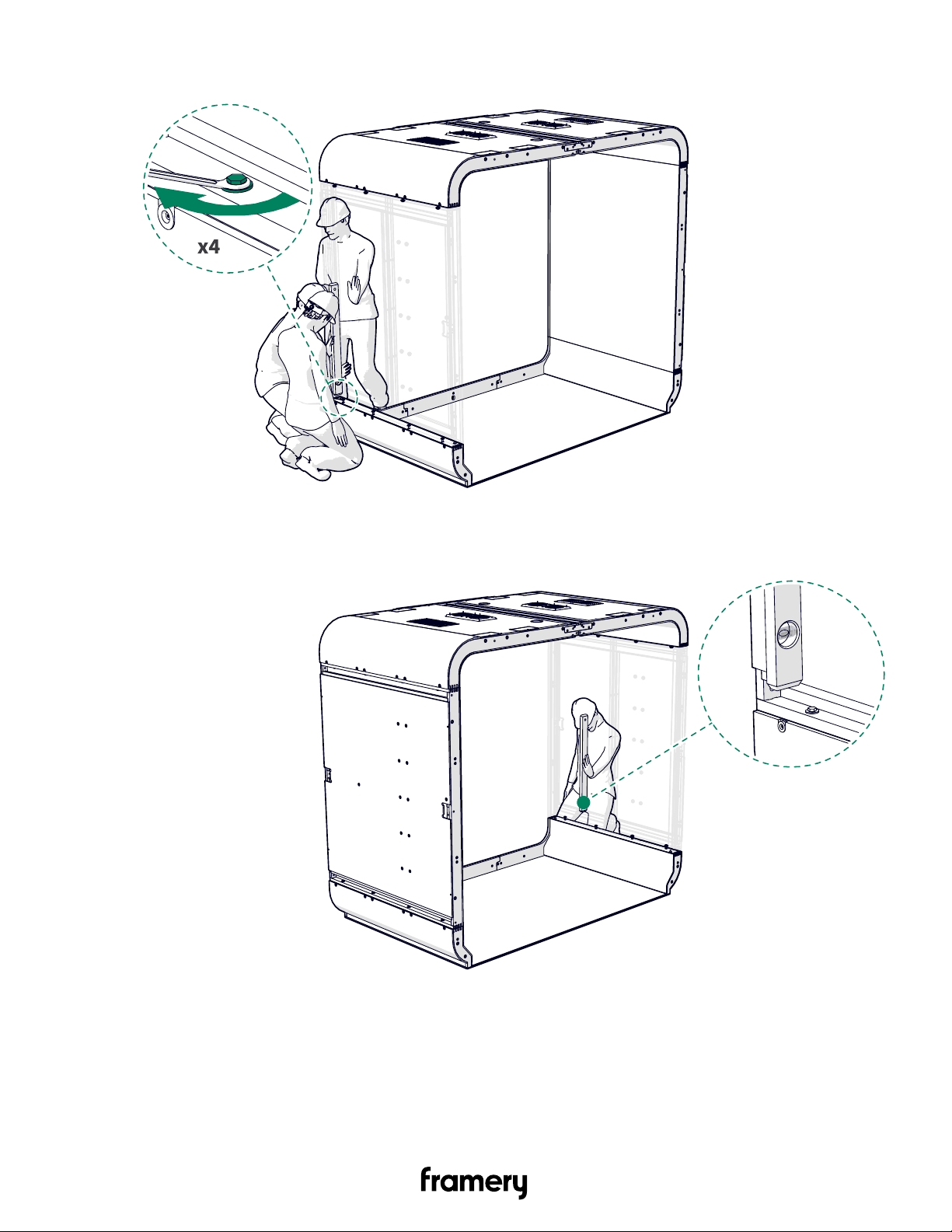
3. Tighten the bolts (4 pcs) on the floor and wall module junction.
4. Check the straightness of the lower right side with a spirit level slightly above the floor and
wall module junction.
30
Framery 2Q Installation Instructions
info@frameryacoustics.com
 Loading...