

FrameCo Mat Master System Series, Mat Master 1260B System, Mat Master 1660B System, Mat Master 1060B System, Mat Master 860B System Owner's Manual & Operating Instructions
www.clubframeco.com
FrameCo - Australia
23 Ceylon Street
Nunawading VIC 3131
Phone: 1800 033 619
Email: frame@frameco.com.au
FrameCo - Euro
Aylesbury
Bucks. UK HP20 1BH
Phone: 020 8144 3651
Email: frame.uk@clubframeco.com
FrameCo - U.S.A.
PO Box 929
California USA 93446
Phone: 805 624 6687
Email: info.usa@clubframeco.com
www.clubframeco.com
FrameCo
MAT MASTER
TM
SYSTEMS
#14225 BEVEL MOUNT CUTTERS
FrameCo - Australia
23 Ceylon Street
Nunawading VIC 3131
Phone: 1800 033 619
Email: frame@frameco.com.au
FrameCo - Euro
Aylesbury
Bucks. UK HP20 1BH
Phone: 020 8144 3651
Email: frame.uk@clubframeco.com
FrameCo - U.S.A.
PO Box 929
California USA 93446
Phone: 805 624 6687
Email: info.usa@clubframeco.com
COPYRIGHT © 2008
MADE IN AUSTRALIA
#14201R Mat Master™ Model #201 Right Handed Bevel Cutter
#14201L Mat Master™ Model #201 Left Handed Bevel Cutter
#14209 Mat Master™ Rule 66cm (26”)
#14211 Mat Master™ Rule 101cm (40”)
#14212 Mat Master™ Rule 150cm (60”)
#14217 Mat Master™ L Rule - 101cm (40”)
#14225 Mat Master™ System 860B
82cm (32”) Cut, Hinged rail, Support. arm, Stops,#201 Bevel & Straight
Cutter and Speed Stop System
#14228 Mat Master™ System 1060B
100cm (40.5”) Cut, Hinged rail, Support. arm, Stops, #201 Bevel &
Straight Cutter and Speed Stop System
#14230 Mat Master™ System 1260B
122cm (47”) Cut, Hinged rail, Support. arm, Stops, #201 Bevel &
Straight Cutter and Speed Stop System
#14240 Mat Master™ Mat Guide Complete
Optional extra Mat Guide for 1260B, 1260-PRO & 1660B
#14233 Mat Master™ System 1660B
160cm (62”) Cut, Hinged rail, Support. arm, Stops, #201 Bevel &
Straight Cutter and Speed Stop System
#14290 Mat Master™ 90º Straight Cutter
#14718 Shadow Box Gauge
#14235 Border Width Extension Kit #1
#14233 Border Width Extension Kit #2
#14236 Mat Board Support Arms
#14237 Double Mat Spacer Block
#14238 Spacer Bar - 5 + 10cm
#14239 Spacer Bar - 15 + 20cm
#14422 Mount Embossing Tool
#14503 Coin Cutter
#14400 GrooveMaster V-Groover Kit
#14401 GrooveMaster Gauge
#14250 Mat Master™Blades x 10/Pk.
#14252 Mat Master
™
Blades x 50/Pk.
#14253 Mat Master
™
Blades x 100/Pk.
#14404 GrooveMaster
™
Blades x 10/Pk.
#14405 GrooveMaster
™
Blades x 50/Pk.
#14406 GrooveMaster
™
Blades x 100/Pk.
#14513 Mat Master
™
Circle Cutter Arm
#14514 Mat Master
™
Circle Cutter Arm & #201 Bevel Cutter
#14515 Mat Master
™
Circle Cutter attachment for GrooveMaster
™
#14516 Mat Master™Circle Cutter attachment for Pencil Holder
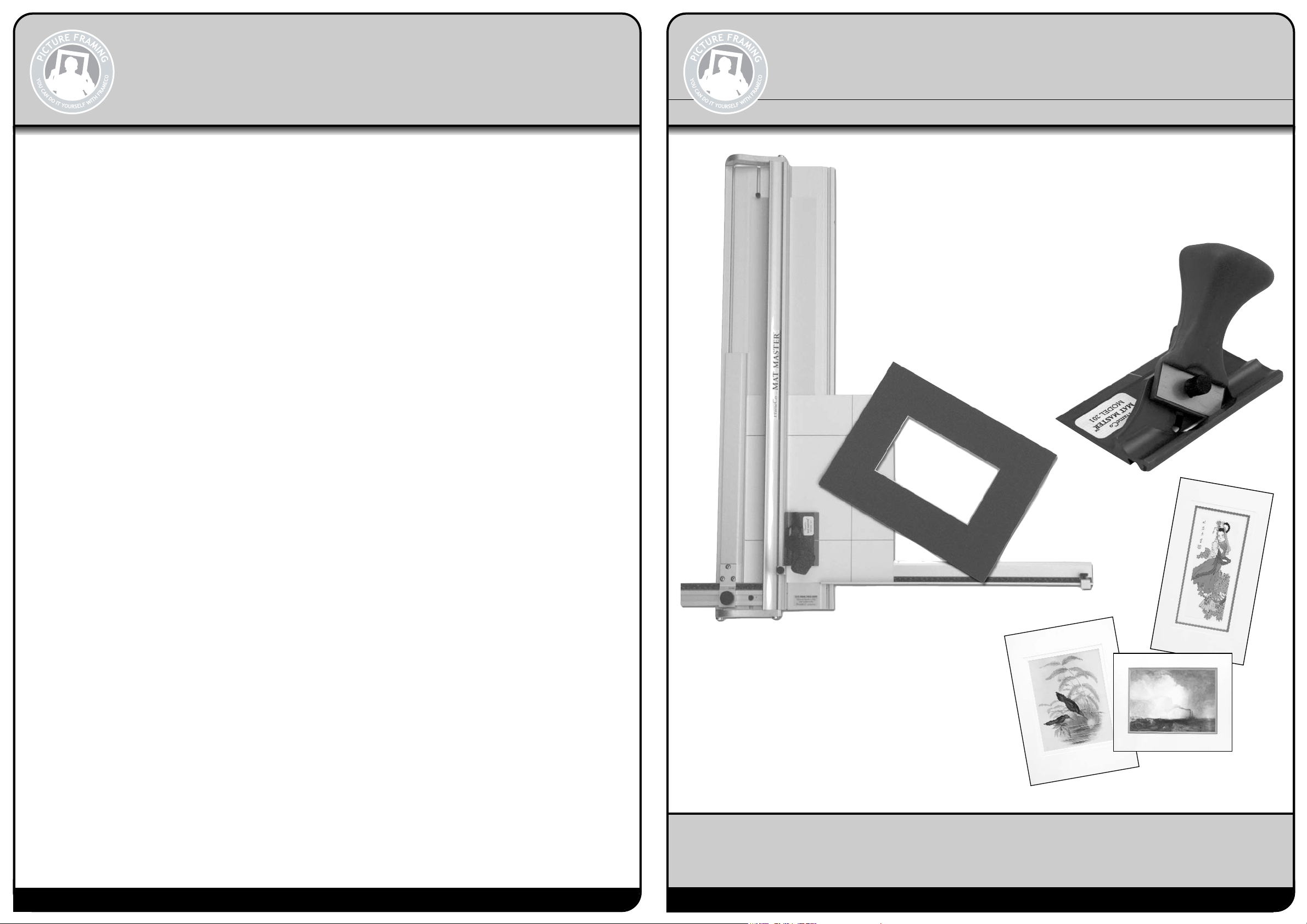
Mat Master™ Products
OWNERS MANUAL & OPERATING INSTRUCTIONS
Mat Master™ 860B System
Mat Master™ 1060B System
Mat Master™ 1260B System
Mat Master™ 1660B System
Welcome and thank you for purchasing a FrameCo Mat Master System.
Through these instructions we will endeavour to show you the benefits of
the system and how easy it is for you to cut and decorate your own mounts.
Revised: 1 October 2008
perfect bevels everytime
www.clubframeco.com
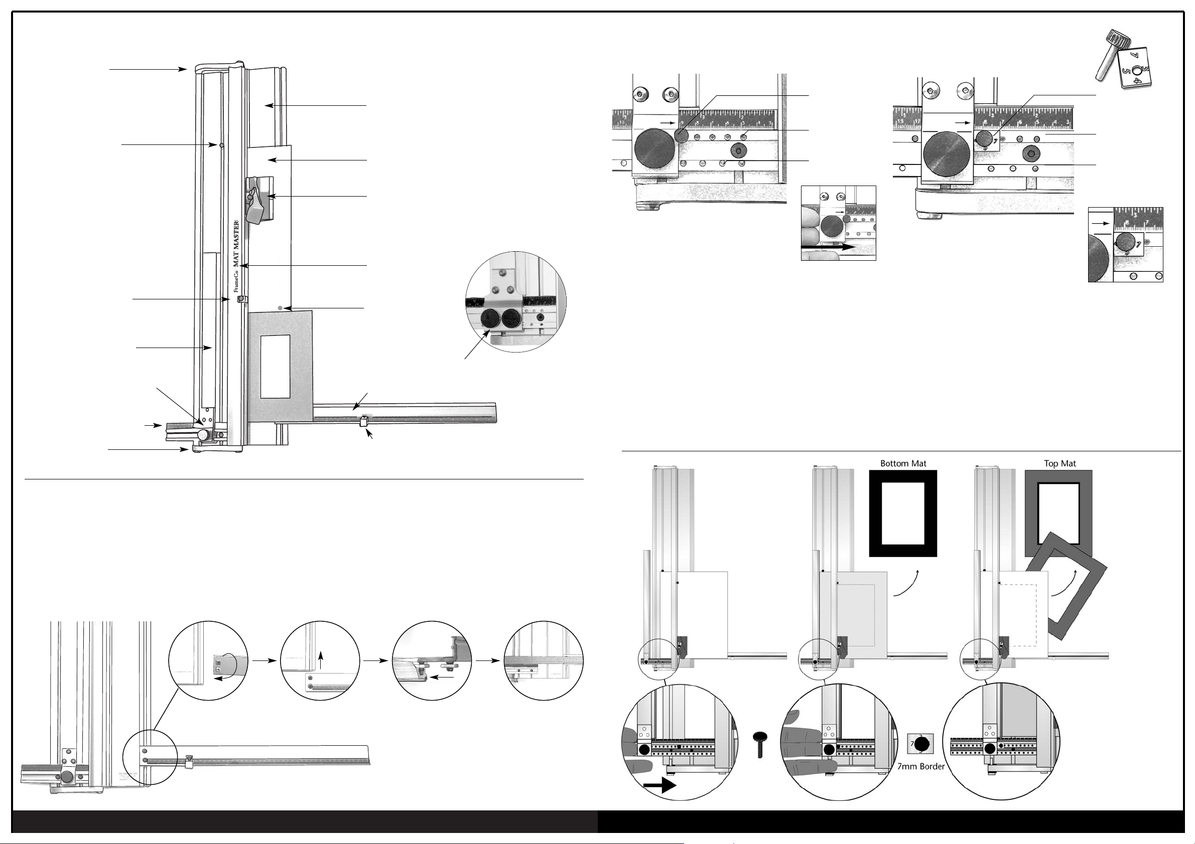
Speed Stop Pin
1 cm
graduations
A new approach for accurate settings. Sometimes it is difficult
to set the Border Width Guide exactly on the rule markings you
require. With the FrameCo Speed Stop it is easy to have
accurate and repeatable settings everytime. The pin holes are
set at 1cm or 1/2” spacings. For sizes between these settings
the measuring block is used. Set the pin into the hole opposite
the size required. Slide the stop along the guide until you feel
it touch the Pin, then lock the Border Width Mat Guide into
place. fig. 1
fig. 1 Slide the stop
along until it
reaches the
Pin
1/2” inch
graduations
Accurate settings are also required for double mats. The Double Mat
Spacer Block option allows you to make these settings easily for double
mats. The blocks are in metric sizes and have sides of different widths.
ie. 3mm - 1/8”, 4mm - 5/32”, 5mm - 3/16” and 7mm - 1/4”.
To cut a mat with an outside width of 6.5cm the Block and Pin is placed
in the 6cm locater hole with the block set on the 5mm side... thus a
total width of 6.5cm. The Block is especially valuable when cutting
double mats. It is easier to use the Speed Pin and Block to cut narrow
double mats rather than rely on settings made manually.
Double Mat
Measuring
Block
1 cm
graduations
1/2” inch
graduations
Double Mat Block
& Pin located on
Border Width Guide
Speed Stop System
Standard on the 860B, 1060B, 1260B & 1660B
Schematic Diagram
The Cutter can be used without installing the Right Support Arm.
The mount cutters come fully assembled apart from attaching the
Right hand Support Arm. The plastic bag contains two screws,
two nuts and one allen key.
Fit the two allen screws and nuts into the two holes in the end of
the Support Arm.
The two nuts fit into the slot located in the base, and the end of
the Support Arm fits neatly into the recess.
Align the Support Arm so that it is parallel to the border width
gauge, by placing a straight edge or ruler across the base.
Tighten the two screws with the allen key provided.
The Support Arm can be removed for storage, and to help
reposition it next time, mark its position with a pencil line.
It will then be easier to align when you reassemble the machine.
Setting up the Support Arm
Anodised Aluminum Base
Dual Locking Screws on 1060B
Slip Mat -inserted when bevel cutting
Bevel Cutting Head
Hinged Cutting Rail
Right Support Arm (not included in 560B)
Measuring stop
Arm Hinge
Border Width Gauge
Production Stop
Border Width Back Stop
Arm Hinge
Slip Mat Stop
Measure Indicator arrow
Attach screws and
nuts onto arm
Turn arm over and align
with aluminium base
Place arm in to base Use a metal ruler to
align arm parallel with
border width gauge
1
J
#14237 Double Mat Spacer Block
Mat Board Stop

www.clubframeco.com
perfect bevels everytime
Ideal for measuring and cutting border widths up to 40cm (16”).
The scale and gauge is also very useful when cutting multi
opening mounts. Pack contains 40 cm gauge and accessories.
Two 30cm (12”) support arms. The arms act as a support
for the mat board when cutting large pieces. Pack contains 2
support arms and all accessories.
To cut accurate mats with a wider offset base, quickly and easily. The spacer
bar is placed in the cutter between the Border Width Gauge and the edge of
the mat board to be cut. To mark out and cut a mat with 6cm border top and
sides, with a 7cm base, the Border Width Gauge is set at 7cm. Draw the line
and insert the 1cm Offset Spacer Bar, then draw the remaining lines, this will
reduce the border width size to 6cm. Then repeat this step by cutting with
the Mat Master
™
#201 Bevel Cutter. Quick, easy and more convenient than
changing settings for each cut.
Offset Spacer Bar - 5 + 10mm
Offset Spacer Bar - 15 + 20mm
Option for: 860B, 1060B,
1260B & 1660B
Option for: 860B, 1060B,
1260B & 1660B
Border Width Extension Kit Mat Board Support Arms
Option for: 860B, 1060B,1260B & 1660B
Offset Spacer Bars
Mat MasterTMDeep Cut Blades Mat MasterTMCircle Cutter
Mat MasterTM#101 Straight Cutter
Cutting Mount Board to Size
Mat MasterTM90OStraight Cutter - Deluxe Model
The FrameCo Circle Cutter is an innovative new tool, which
utilises many of the existing FrameCo mat cutters. The Circle
Cutter Arm consists of a swivel point, calibrated scale and
turning handle.
The kit includes all the fittings to attach the FrameCo #201
Bevel Cutter, for cutting bevelled circles and arcs.
Attachments are also available to mount a pencil or coloured
pen and the GrooveMaster
TM
for making circular V-Grooves.
The standard #201 blades cuts bevel mat board 2.2mm thick.
As most mat boards on the world market are only 1.4mm
thick this blade is quite sufficient. To achieve the long deep
bevel cuts required for wrapped mats, the base mat needs to
be 3mm to 5mm thick. Our new Deep Cut Blade will cut a
crisp, clean bevel in 3mm or 5mm fome board.
Mat Master™90º Straight Cutter attaches to the rule for safe and
accurate cutting. The cutters main feature is a retractable blade
and is also fully adjustable with settings to cut paper, Mat Board,
3mm and 5mm Fome Core board.
9
Blade Retaining Screw
#201 Blade
* Takes both Standard:
#201 Blades and Deep Cut Blades
* Takes both Standard:
#201 Blades and Deep Cut Blades
Start/Stop line
Polycarbonate
Wear Strip
The Mat Master™ #201 Push style Bevel Cutter features a
new easy grip designed handle for comfortable and
effortless cutting. The bevel cutting head attaches to
the rule for accurate cutting everytime. Start/Stop indicator line, adjustable
blade depth, retractable blade and is made from precision machined
aluminium and anodised blue. To start cutting, the blade is lowered by
pushing the handle downwards.
Mat Master™ #201 Bevel Cutter
#201 Blade
Blade Retaining Screw
Finger Grip
Our standard pull style cutter is included with all
FrameCo board mounted cutters.
Consists of three blade depth positions. Top hole
position for storage and safety. Middle position,
the blade is set to cut standard mat board. The
lower position is for cutting 3mm fome core and
thick cardboards.
1. First we will need to measure the artwork, and determine the width of the
border.
Example: Artwork size = 400mm x 300mm - 15
3/4
” x 12”
Border size = 60mm - all sizes - 2
3/8
”
Overall size = 400mm + 60mm + 60mm = 520mm
15
3/4
” + 2
3/8
”+ 2
3/8
” = 20
1/2
”
= 300mm + 60mm + 60mm = 420mm
12” + 2
3/8
”+ 2
3/8
” = 16
3/4
”
The overall size of the blank mat should be 520 x 420mm - 20
1/2
” x 16
3/4
”.Measure
up your mount board making the appropriate cut marks on the back of the mat.
2. To cut down a piece of mat board. Position the edge of your mat board
underthe rule (face down) and align the edge of the rule with your cutting
marks.
3. Position the Straight Cutter onto the cutting rule - Cut by pulling the cutter
along the rule.
4. Turn the mat board and repeat for the short side ie. 520mm (20
1/2
”).
Note: You can also cut the mat board down to size by removing the rule from the
base board and using the rule as a straight edge.
fig.1
fig.2
Deep Cut Blade
www.clubframeco.com
perfect bevels everytime
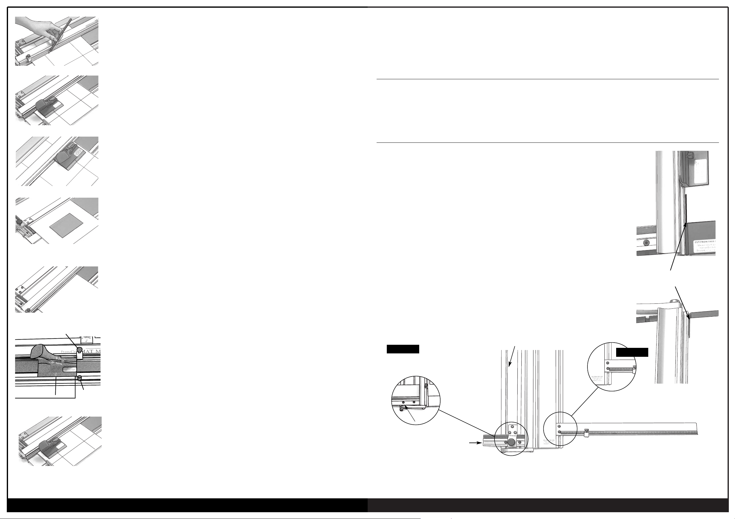
Marking Out the Mount
1. Set the Border Width Gauge to the size required. Use the red measurement indicator arrow
for accuracy. Place the mount under the hinged cutting rail, face down and align it gently up
against the Border Width Arm.
2. Draw a line from top to bottom using a 2H pencil.
3. Rotate the mount board 90
O
and draw the next line.
4. Repeat until you have marked all 4 sides (see fig.3).
Note: (i) Use a 2H pencil for fine light lines. Carry the line to the outer edges of the board
- this makes cutting double mounts easier. Hold the pencil the same way each time.
(ii) You can also use the production stop - see “Cutting a Single Mat using Stops”.
fig. 3 Use 2H Pencil
1. After marking out the mat, attach the cutting head onto the cutting rule (fig 4). The mat
should be under the rule, face down and up against the Border Width Back Stop which has
been set to the size you wish to cut the borders.
2. To begin cutting, align the start/stop silver line on the cutting head just before the start (or
bottom) border line. (fig. 4)
Press the blade into the board by pushing the handle downwards to lower the blade, then
push the cutter away from you up towards the finish line. (fig. 5)
With practice you will be able to eliminate any overcuts or undercuts - see back page
for cuting tips.
3. Release the handle and the blade will retreat from the mat board. Rotate the mat anticlockwise and repeat for the other three sides (fig 6).
Cutting a Single Mount using “Pencil Lines”
Cutting a Single Mat using Production Stop and Mat Board Stop.
A better method for cutting all your mats is to use the production stopand the mat board stop.
This is a faster and more accurate method.
1. Insert the mat, face down, under the rule and position it against the Border Width Back Stop,
which is set at the required border width. Rule all four lines from the top to bottom on the
back of the mat (fig. 7).
2. Leaving the matboard blank under the rule position it approximately mid-way along the
cutter base. Slide the Mat Board Stop down and position it hard up agaisnt the top end
of the mat board blank. Lock the Mat Board Stop in this position.
3. Fit the #201 Bevel cutting head onto the rule, and align the Silver Indicator Line on the head
with the top pencil line. Slide the Production Stop down the rule until it touches the top of
the bevel cutting head. Lock the Production Stop into this position (fig. 8).
4. To begin cutting, position the cutting head at the bottom of the mat so that the silver
indicator line is aligned with the bottom pencil line (fig 9). Push the blade into the mat, then
push the head upwards along rule until it hits the Production Stop. The cutting head will now
be in line with the top pencil line.
5. Rotate the mat clockwise, starting each cut from the bottom pencil line, then cutting up to
the stop for each side. Repeat for all the remaining sides.
fig. 5
fig. 4
fig. 6
fig. 8
fig. 7
Smaller Border Sizes
Maintenance
Squaring & Alignment Testing
If you wish to cut a border size less than 5cm (2”) an additional
spacer needs to be added between the Border Width Arm and
the mount.
Cut a piece of mount board 25mm or 1” and insert this between
the Border Width Arm and the mount to be cut.
Set the Border Width scale out that additional measurement.
A second method for cutting narrow board widths, is to cut the
mount larger than required, then to trim off the excess, thereby
reducing the mount to the required size.
1. Cleaning - Keep your cutter clean and dust free. Clean the base with a solvent such as methylated spirits or lighter fluid.
Do not oil the guide rail or the cutting head.
2. Do not screw or attach your mount cutter to a bench. Excess heat can cause the cutter base to warp.
Always place the cutter on a firm solid table. Do not store the cutter in the upright position for long periods.
A simple exercise to check that the Mat Master machines are cutting square.
1. Take a sample sheet of mount board approximately three quarters the length of the mount
cutter and approximately 30cm (12”) wide. Place it in the cutter and under the hinged
cutting rail, and up against the border width arm. Set the Border Width Gauge at half the
width of the sample sheet so that the guide rail is approximately in the middle of the
sample sheet.
2. With a sharp knife make a cut approximately 25mm (1”) long - one a the top and one at
the bottom of the sample sheet.
3. Turn the sample sheet over from left to right (ie. upside down), place it back under the
cutter rail and against the border width arm. Make two new cuts, one at the top and
bottom of the sample sheet. If the two cut marks line up, the machine is square ie. the
cutting rail is parallel to the Border Width Arm.
4. When the cut marks do not line up, you will need to adjust the Border Width Arm by half
the distance between the cut marks as follows.
Adjustment
5. Loosen the Support Arm and move downwards out of the way.
6. Loosen the outer screw in the base of the Border Width Gauge, then gently tap the gauge
up or down to realign the Border Width Arm.
7. Reposition the Right Support Arm and re-align it with the aid of a straight edge.
Loosen Right Support Arm and
move downwards or remove
Border Width Arm
Remove the Border Width Arm
Loosen outer screw in the
base of the gauge
To make sure the Mount Cutter is
cutting square both cuts should align
when the mount board is flipped over.
Border Width Gauge
Right Hand Support Arm
STEP 6
STEP 5 & 7
Matboard Stop
Production Stop
fig. 9
www.clubframeco.com
perfect bevels everytime
fig. 41 Anti-clockwise to lower blade
fig. 42 Ideal blade depth
Changing & Adjusting the Blade Depth
Cutting Position
Over & Under Cuts
fig. 43
fig. 44
Changes to the Depth Adjustment Screw moves the depth stop..
ie the blade travels further. It does not actually lower the blade.
1. The blade is held in place with one central screw.
2. Release and remove the used blade by removing the central screw.
3 The blades are packed in packs of 5 or 10 and can be used both ends.
4. Fit a new blade into the handle with the sharp edge down.
5. Replace the central screw.
The cutting depth of the blade can be adjusted using the allen key supplied.
Rotate the depth adjustment screw, located in the base of the cutting head, anticlockwise
to lower the blade (see fig. 41). One full turn lowers the blade by approximately 0.1mm.
The blade should only just protrude through the mount board for a clean and easy cut.
Measure the depth against a sample of the mount board as shown in fig. 42.
Note 1: When using the bevel cutter on your machines always have a slip mat in position under
the mount being cut. Use a piece of standard mount board cut to size.
Note 2: Hooks - If the blade is set to low it may flex and cause a small “hook” at the start of the
cut. Set the depth correctly - see fig.42.
Cutting a new mount takes very little effort.
The way you hold and push the cutting head is important as it effects the quality of the cut.
To start cutting, push the blade firmly into the mount board so that the blade penetrates all the
way through the mount board. Before starting to cut, lower your arm, so that you are cutting
along the line, rather than pushing downwards (see fig. 43).
If you find that cutting is hard work review your cutting position and lower your arm a little
to make it easier.
Always practice on a spare board before making your first cut, or after changing the blade depth.
Do not use self healing plastic mats under the cutting rail. Strips of standard mount board are
best suited as slip mats.
Make sure you are not cutting into old cuts in the slip mat as these may cause the blade to cut
away from the rail. The slip mat stop (see fig. 44) can be located into any slot so that any sized
piece of mount board can be used under the cutting rail as a slip mat.
The stop can be located in any one of the grooves in the base board.
Over Cuts
If the blade depth is adjusted correctly, then any over cuts will be due to YOU cutting too far past the top finishing line or starting
too early before the bottom start line. Adjust YOUR starting and stopping position to eliminate these over cuts.
Under Cuts
If the drop out does not fall out after cutting your mount, do not push it out as this may tear the corners. Take a spare blade and
extend the cut so that the centre piece falls out. The ideal is to have the centre fall out each time with no over cuts and no
undercuts. As with over cuts, if you find that the mat is undercut then simply adjust your starting and stopping position relative to
the start and stop lines ie. start a little earlier and finish a little further. You have to find the ideal start and stop posi tion relative to
the size pencil you use (2H is ideal), and how you draw the line (holding the pencil close against the rail is ideal).
7
fig. 40
Standard Blade
Deep Cut Blade
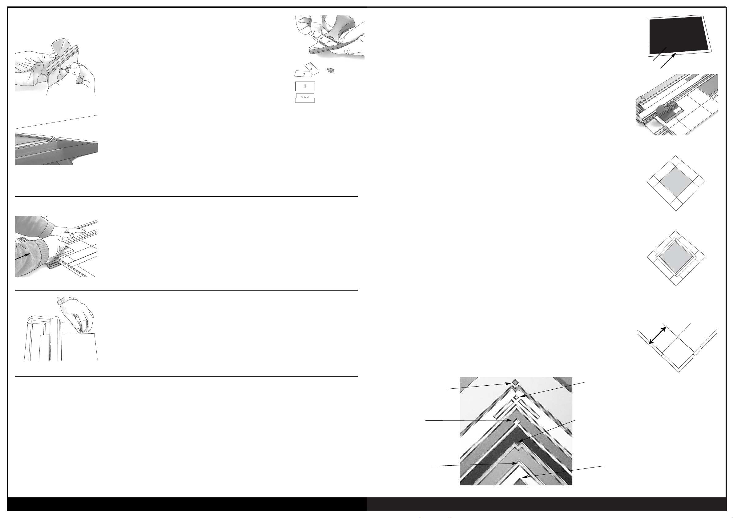
Cutting a Double Mount
A Double or Triple Mat on an image will add more interest to the design of your framing.
By choosing colours that compliment the picture, the image will be enhanced and become
sharper. These colours will also help lead the eye from the frame into the picture, which is
the central focus.
The “secret” to cutting double mounts, so that the inner mount is exactly parallel to the
outer, is not to cut two separate mounts! You can achieve perfect double mounts every time
by following the method below.
The best way, is to cut the top first, stick the two together,
then cut the bottom mount.
Here is how to do it: -
Example: 20cm x 30cm double mount with 6cm border.
1. Cut the blank for the top mount 20 x 30cm. Cut the blank for the bottom mount a little
smaller - 19 x 29cm (see fig. 13).
2. Cut out the window in the top mount with a 5.5cm border, keep the fallout
(see fig. 14).
Note: (I) As we are cutting a double mount the top border size needs to be 5mm
smaller to show the bottom mount.
(II) Remember, we cut all mounts from the reverse side - so all our pencil
markings are on the back of the mount.
3. Place the top mount face down on your table top. Replace the drop out back into the
hole (see fig. 15).
4. Apply strips of double sided tape to the back of the mount, plus an extra piece in the
centre of the drop out. Then attach the bottom mount face down to the rear of the top
mount (see fig. 16).
5. Now mark out on the back of the bottom mount for a 6cm border - use the outer edges
of the top mount as your reference edge for measuring (see fig. 17).
The reason for cutting the bottom mount smaller is to ensure that you use the top
mounts outer edges for both border measurements. That way the sides of the double
mount will be parallel .
Hints: (I) To cut a triple mat repeat the procedure used on the bottom mat, you are only
limited by your own imagination.
(II) The cutting head should always be inside the window you are cutting.
A new mat blade is cheaper than new mat board so always use a sharp blade.
fig. 13
top mount
bottom mount
fig. 14
fig. 15
fig. 16 Apply double sided
tape to back of mount
fig. 17
Stepped (Offset)
Combination Mount
Inset Mount
Double Mount
Combination Mount
Stepped (Offset) Mount
Single Mount
X
Slip Mats
www.clubframeco.com
perfect bevels everytime
GrooveMaster™
V-Grooving with GrooveMaster™
GrooveMaster™ is a revolutionary new hand tool for cutting decorative V- Grooves into all types of
picture framing mount board. V-Grooves add a stylish look to all your framing. It is that creative
touch that gives your picture a professional finish.
Marking out the Mount
1. A V-groove can be located anywhere on the mat face. But as the main function of the
V-groove is to guide the viewers eye into the picture it is best placed on the outer or inner
edge of the mat and not in the middle. This is what we have found to be visually more
pleasing. Remember that there is no one correct position. We normally recommend to locate
the V-groove 1.5cm (1/2") from the bevel edge of the mount - position #2 on the gauge.
Cut the mount opening first – then cut the v-groove.
2. Use the Corner Gauge to mark out the start and finish lines on the front surface of the mount.
The slots in the gauge are approx. 1cm apart and you can use the top or bottom
of the slot. Just remember to use the same position on each corner. (fig. 29)
We recommend position #2 on the gauge. Draw short "light" lines on the surface of the mount
making sure the ends of the lines meet. These are your start and finish positions.
Setting up to V-Groove
3. Place the mount face up under the cutting rail. It may be more convenient if you detach
the Border Width Arm from the machine as this will not be used. Position the mount down
against the squaring arm so it does not move while making the V-Groove cut.
4. Attach the Groove Master to the cutting rail. By moving the mount, position
the GrooveMaster over the first set of corner lines, checking that the blades are aligned with
the downward line. (fig. 30)
Now move the GrooveMaster to the bottom set of lines. Align the blades over the lines by
moving the mount under the rail. Repeat the process making sure the mount is in the correct
position. This process will ensure you cut a straight v-groove.
5. Starting at the top position, press the blades into the mount and with a smooth constant
pressure pull the cutter downwards to the finish position. (fig. 31)
Stop when you see the intersection line appear in the sight hole. Remove the GrooveMaster
carefully so that you do not tear away the waste material.
More control and smoother cutting is obtained if the 3rd finger is located in the index hole,
rather than the 2nd finger (see figure. 35)
6. Rotate the mount clockwise ready to cut the next side. Position the mount and the
GrooveMaster on the next set of corner cross lines and cut down to the first groove. Repeat
for the third and fourth side.
Note: We have found for best results to cut from
the reference marks down to a groove.
fig. 29
fig. 30
fig. 31
fig. 32
Changing Blades
GrooveMaster™ as a Carving Tool
Blades need to be changed once they have lost their sharp edge. We have noticed that the
waste cut out strip curls up more, once the blades lose their sharpness. So change the blade
once this starts to occur.
The correct setting of the blades is critical for successful v-groove cutting.
The blades need to be aligned so that the tip of the blades are touching and level,
but do not overlap each other.
Our suggestion method for setting the blades correctly is to firstly fit two new blades, but keep
the front locking blades loose.
Check the alignment of the blades.
The tips should be level - not overlapping and just touching.
Tips:
1.
Always make a test cut on the waste board first.
2. If the blades are set correctly a business card can be just passed through the blades with
some resistance - not too tight; not too loose! (see figure 33 & 34).
3. More control and smoother cutting is obtained if the 3rd finger is located in the index hole,
rather than the 2nd finger (see figure. 35)
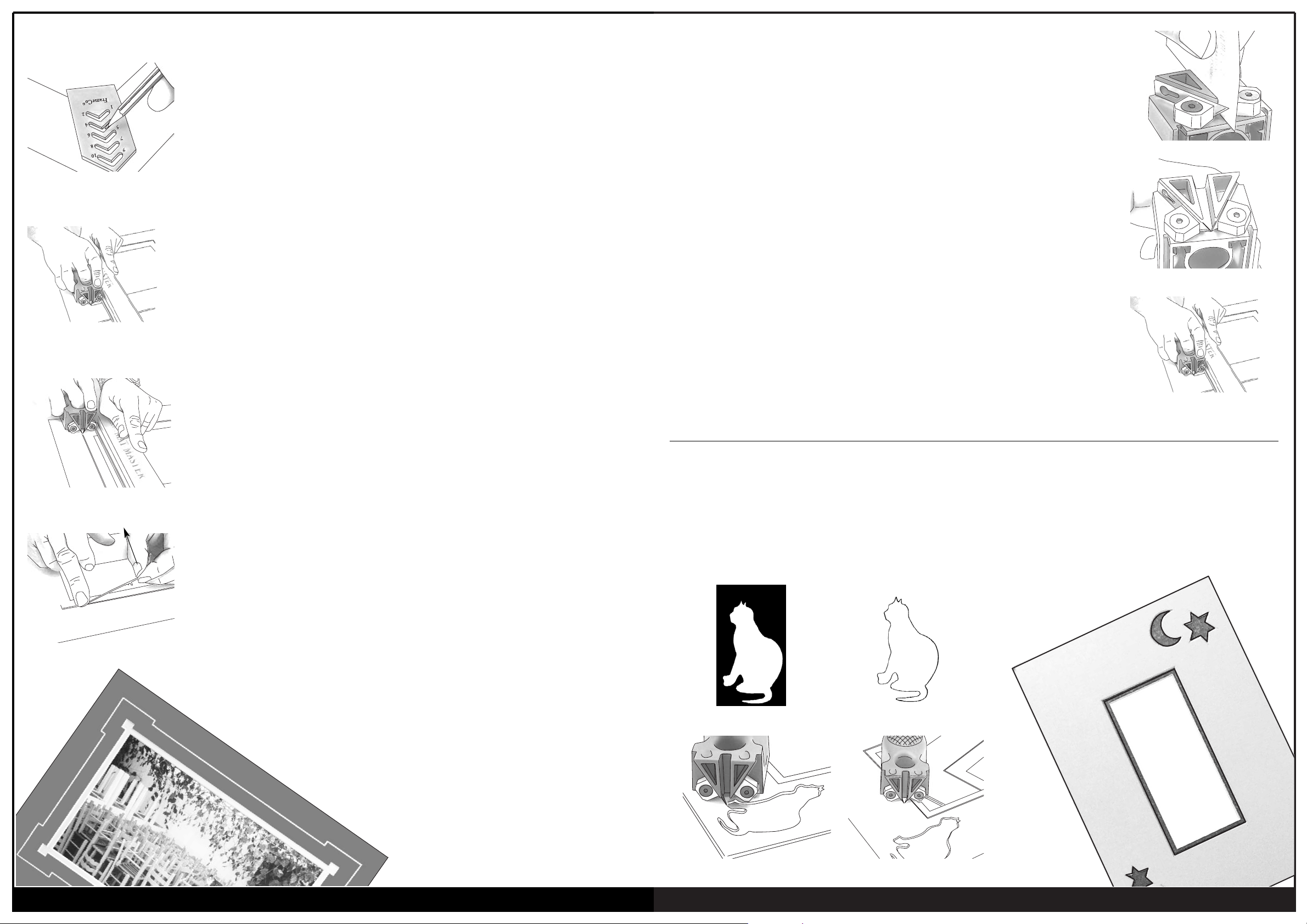
Turn your GrooveMaster into a versatile hand carving tool by changing the blade setting.
Remove one blade carefully, or position it so that it will not cut the board. Position the other
blade further out so that it cuts all the way through the board you are cutting.Ideas for cut outs,
come from stencils. Simply trace around the stencil onto the face of the mount board, then cut
out the pattern (see figures 36 - 39).
fig. 33
fig. 34
fig. 35
fig. 36
fig. 37
fig. 38 fig. 39
 Loading...