

Page 1
February 2013
Page 1
1999-2013 © FRACTUS, S.A.
Fractus® TVNow
TM
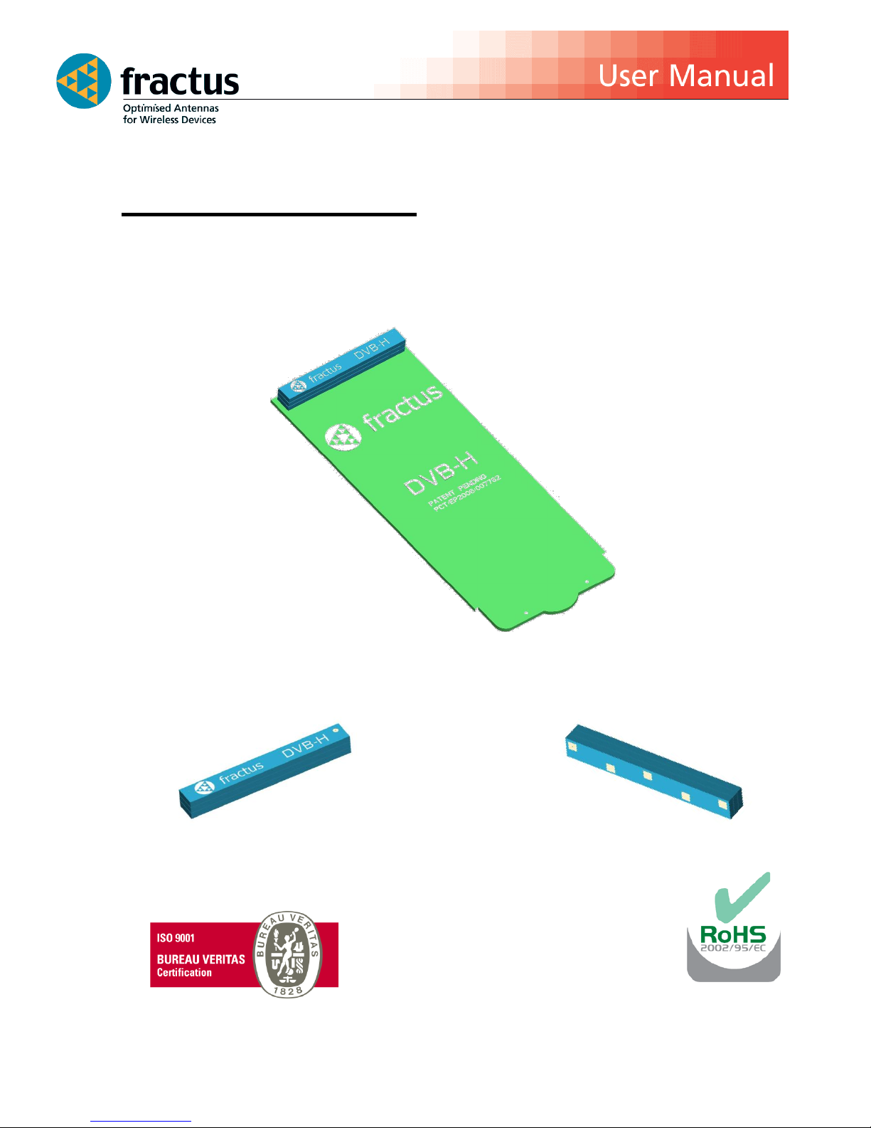
Mobile TV Dual-Band DVB-H (UHF + L Band) Antenna
Antenna Part Number:
FR01-B1-S-0-047
Page 2
February 2013
Page 2
1999-2013 © FRACTUS, S.A.
TABLE OF CONTENTS
1. ANTENNA DESCRIPTION ______________________________________________________ 3
2. QUICK REFERENCE GUIDE _____________________________________________________ 3
3. ELECTRICAL PERFORMANCE ___________________________________________________ 4
3.1. TVNow EVALUATION BOARD ________________________________________________ 4
3.2. RADIATION PATTERN AND GAIN _____________________________________________ 5
3.3. CAPABILITIES AND MEASUREMENT SYSTEMS ___________________________________ 6
4. MECHANICAL CHARACTERISTICS _______________________________________________ 7
4.1. DIMENSIONS AND TOLERANCES _____________________________________________ 7
4.2. SPECIFICATIONS FOR INK __________________________________________________ 7
5. ASSEMBLY PROCESS _________________________________________________________ 8
6. ANTENNA FOOTPRINT (as used in the evaluation board) ____________________________ 10
Any update on new patents linked to this product will appear in http://www.fractus.com/index.php/fractus/patents
All information contained within this document is property of Fractus and is subject to change without prior
notice. Information is provided “as is” and without warranties. It is prohibited to copy or reproduce this
information without prior approval.
Fractus is an ISO 9001:2008 certified company. All our antennas are lead-free and RoHS compliant.
Page 3
February 2013
Page 3
1999-2013 © FRACTUS, S.A.
1. ANTENNA DESCRIPTION
The TVNowTM is an off-the-shelf internal antenna solution specifically designed for DVB-H applications,
covering UHF and L-band requirements.
TVNow minimises your product development cost and time. It combines small size and high performance
making TVNow an optimal choice for your portable DVB-H applications.
APPLICATIONS
Mobile phones
Personal Media Player (PMP)
Ultra Mobile PC (UMPC)
Secure Digital (SD) cards
BENEFITS
Reduced Form Factor
Modularity - SMD
Superior Performance
High Isolation (DVB-H and GSM)
2. QUICK REFERENCE GUIDE
Technical Features
Frequency Range
With GSM Coexistence
470 – 698 MHz
1670-1675 MHz
Gain Curve
>2 dB margin with DVB-H
recommendations
Radiation Pattern
Omnidirectional
Gain Flatness (horizontal
diagram)
±2 dB
Weight (approx.)
1.9 g
Temperature
-40 to 85º C
Impedance
50 Ω
Dimensions (L x W x H)
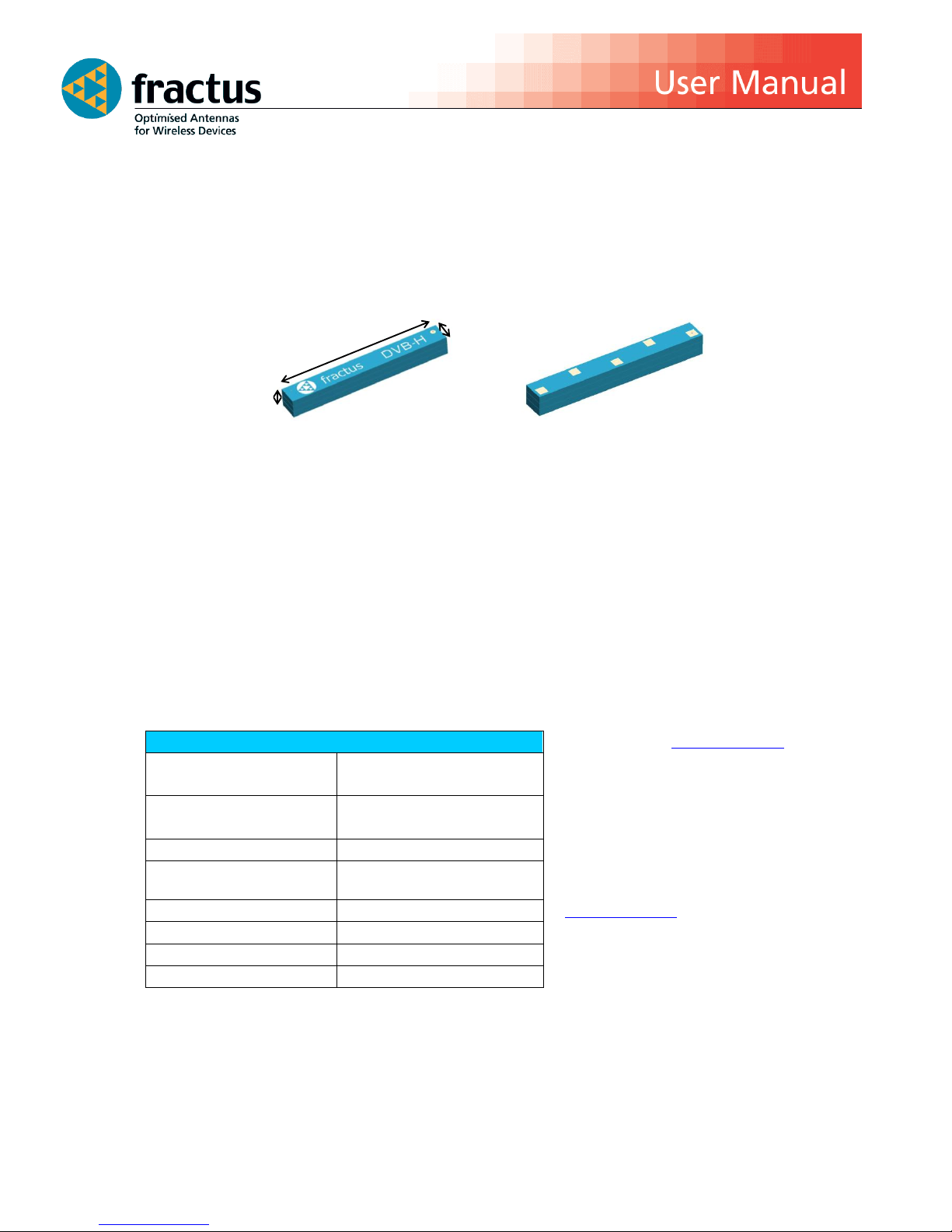
40.0 mm x 5.0 mm x 4.8 mm
Table 1 -Technical Features. Measures from the evaluation board
(107.0 mm x 42.7 mm x 1.0 mm PCB)
TOP
BOTTOM
Please contact [email protected] if you
require additional information on antenna
integration or optimisation on your PCB.
FRACTUS S.A.
www.fractus.com
Tel: +34 935442690
Fax: +34 935442691
40.0 mm
4.8 mm
5.0 mm
Page 4
February 2013
Page 4
1999-2013 © FRACTUS, S.A.
3. ELECTRICAL PERFORMANCE
3.1. TVNow EVALUATION BOARD
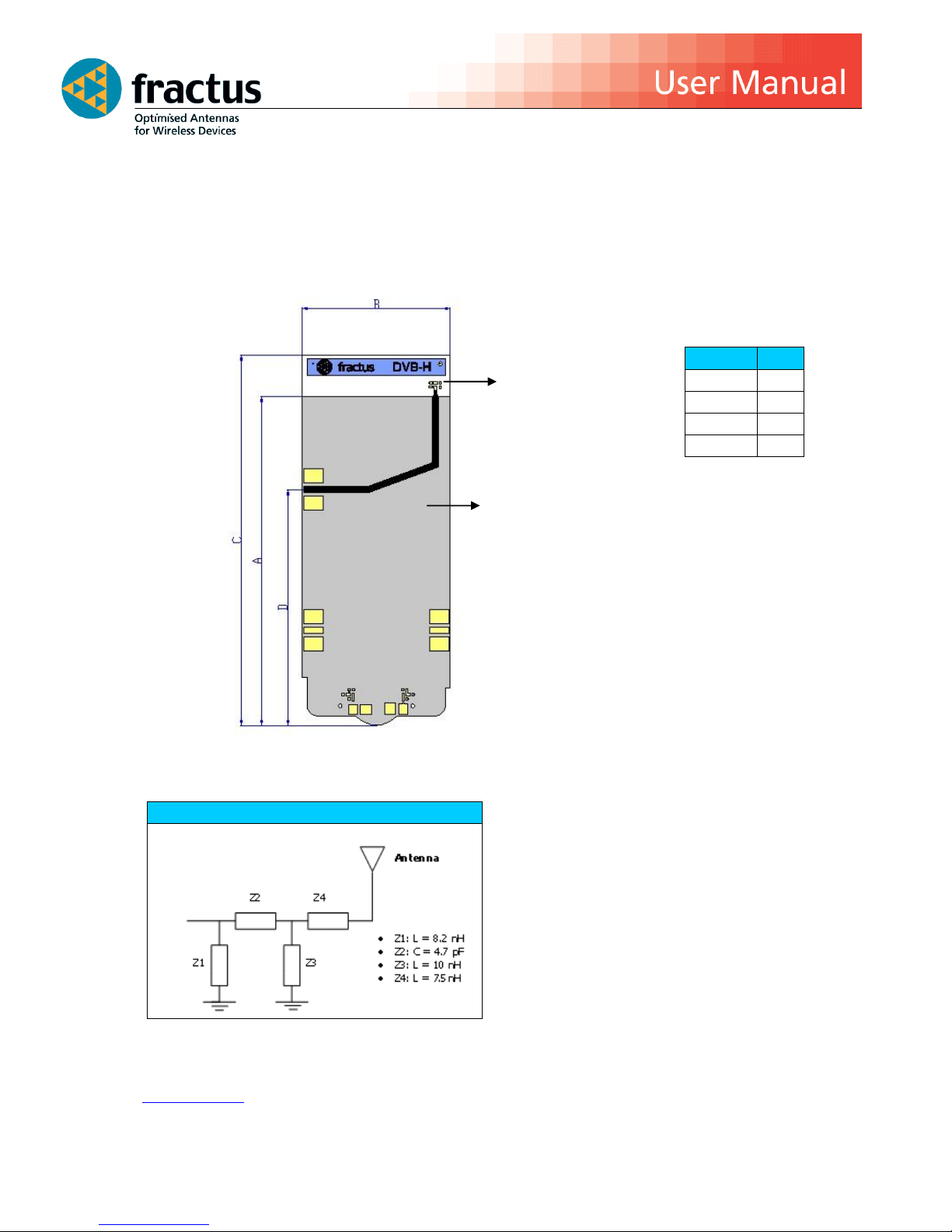
The configuration used in testing the TVNowTM dual band (UHF+Lband) DVB-H antenna is displayed
in Figure 1.
Figure 1 – TVNowTM Dual Band (UHF+Lband) DVB-H
Measure
mm
A
95.0
B
42.7
C
107.0
D
68.0
Tolerance: ±0.2 mm
Material: The evaluation board
is built on FR4 substrate of 1.0
mm thick.
Antenna clearance
(white colour)
Ground plane
(grey colour)
Matching Network Values
Note: Optimal matching network values may vary depending on the antenna environment. Please, contact
[email protected] for additional support to integrate the antenna in a specific application.
Page 5
February 2013
Page 5
1999-2013 © FRACTUS, S.A.
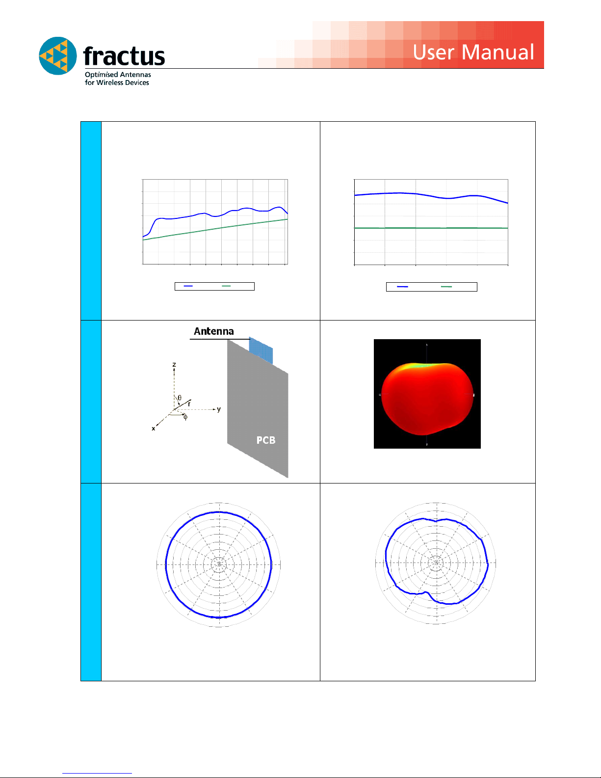
3.2. RADIATION PATTERN AND GAIN
Table 2 – Antenna Gain across UHF and L-band
GAIN
Radiation Pattern
3D
Radiation Pattern
-40
-35
-30
-25
-20
-15
-10
-5
0
180
240
270
310
330
120
150
0
30
60
90
210
-40
-35
-30
-25
-20
-15
-10
-5
0
180
240
270
310
330
120
150
0
30
60
90
210
TVnow
TM
performance in L US bands
-6
-5
-4
-3
-2
-1 0 1
1660
1665
1670
1675
1680
1685
frequency (MHz)
Gain (dBi)
Gain
ETSI Specs
Gain
(dBi)
TVNow
TM
Performance Vs UHF DVB-H Specs
-14
-12
-10
-8
-6
-4
-2
0
470
495
520
545
570
595
620
645
670
695
Frequency (MHz)
Gain
ETSI Specs
H Plane (=90º) Plane XY
E Plane (=90º) Plane YZ
Page 6
February 2013
Page 6
1999-2013 © FRACTUS, S.A.
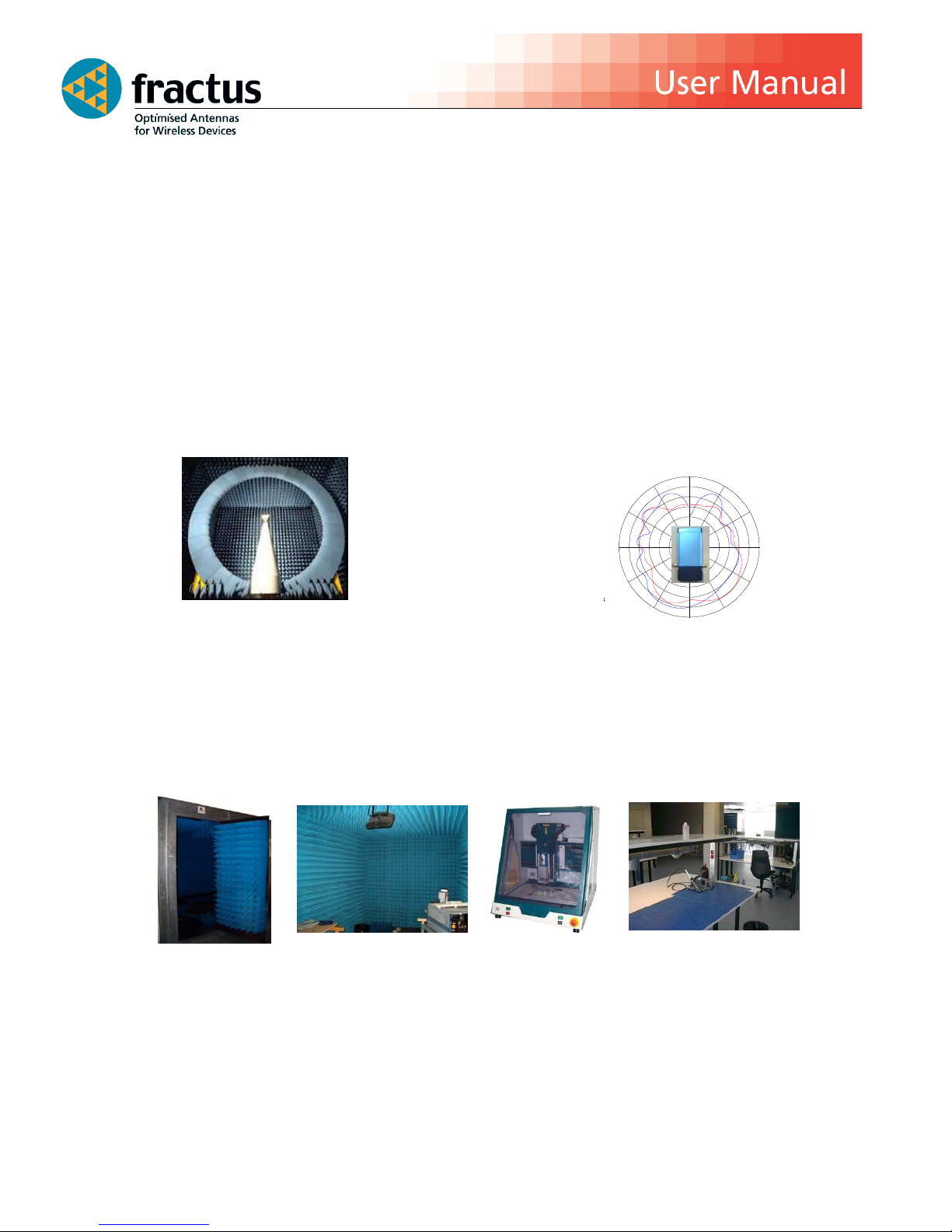
3.3. CAPABILITIES AND MEASUREMENT SYSTEMS
Fractus specialises in the design and manufacture of optimised antennas for wireless applications, and with
the provision of RF expertise to a wide range of clients. We offer turn-key antenna products and antenna
integration support to minimise your time requirements and maximize return on investment throughout the
product development process. We also provide our clients with the opportunity to leverage our in-house
testing and measurement facilities to obtain accurate results quickly and efficiently.
0
30330
60300
90270
120240
150210
180
-30
-25
-20
-15
-10
-5
0
5
0
30330
60300
90270
120240
150210
180
-30
-25
-20
-15
-10
-5
0
5
Radiation
Pattern
&
Efficiency
SATIMO’s STARGATE 32
Anechoic and semi-anechoic chambers and fully equipped in-house lab
Page 7
February 2013
Page 7
1999-2013 © FRACTUS, S.A.
4. MECHANICAL CHARACTERISTICS
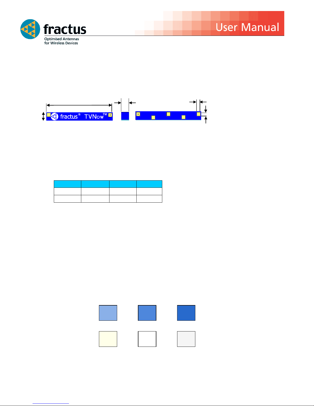
4.1. DIMENSIONS AND TOLERANCES
Figure 2 – Antenna Dimensions and Tolerances
Measure
mm
Measure
mm
A
40.0 0.2
C
4.8 0.2
B
5.0 0.2
D
2.0 0.1
The TVNowTM Dual Band (UHF+Lband) DVB-H antenna is compliant with the directive 2002/95/EC on the
restriction of the use of hazardous substances (RoHS). Please contact your account representative if you
require a green certificate (RoHS report.)
4.2. SPECIFICATIONS FOR INK
Next figure shows the correct colours of the antenna:
The black hole located on the front of the antenna,
provides a visual cue to mounting the antenna. It is
located above the feed point of the antenna and is
included to decrease possible manufacturing error.
Note: all antenna pads
(feed point and mounting
pads) have the same
dimensions.
Acceptable colour range
C B A D D
Page 8
February 2013
Page 8
1999-2013 © FRACTUS, S.A.
5. ASSEMBLY PROCESS
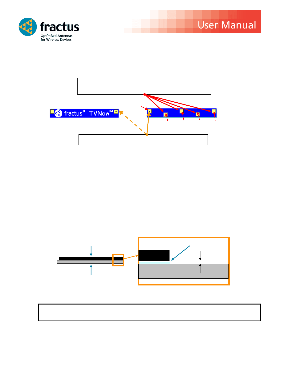
Figure 3 shows the back and front view of the TVNowTM Dual Band (UHF+Lband) DVB-H antenna , and
indicates the location of the feeding point and the mounting pads:
Figure 3 –Views of the TVNowTM dual band (UHF+Lband) DVB-H antenna
As a surface mount device (SMD), this antenna is compatible with industry standard soldering processes. The
basic assembly procedure for this antenna is as follows:
1. Apply a solder paste to the pads of the PCB. Place the antenna on the board.
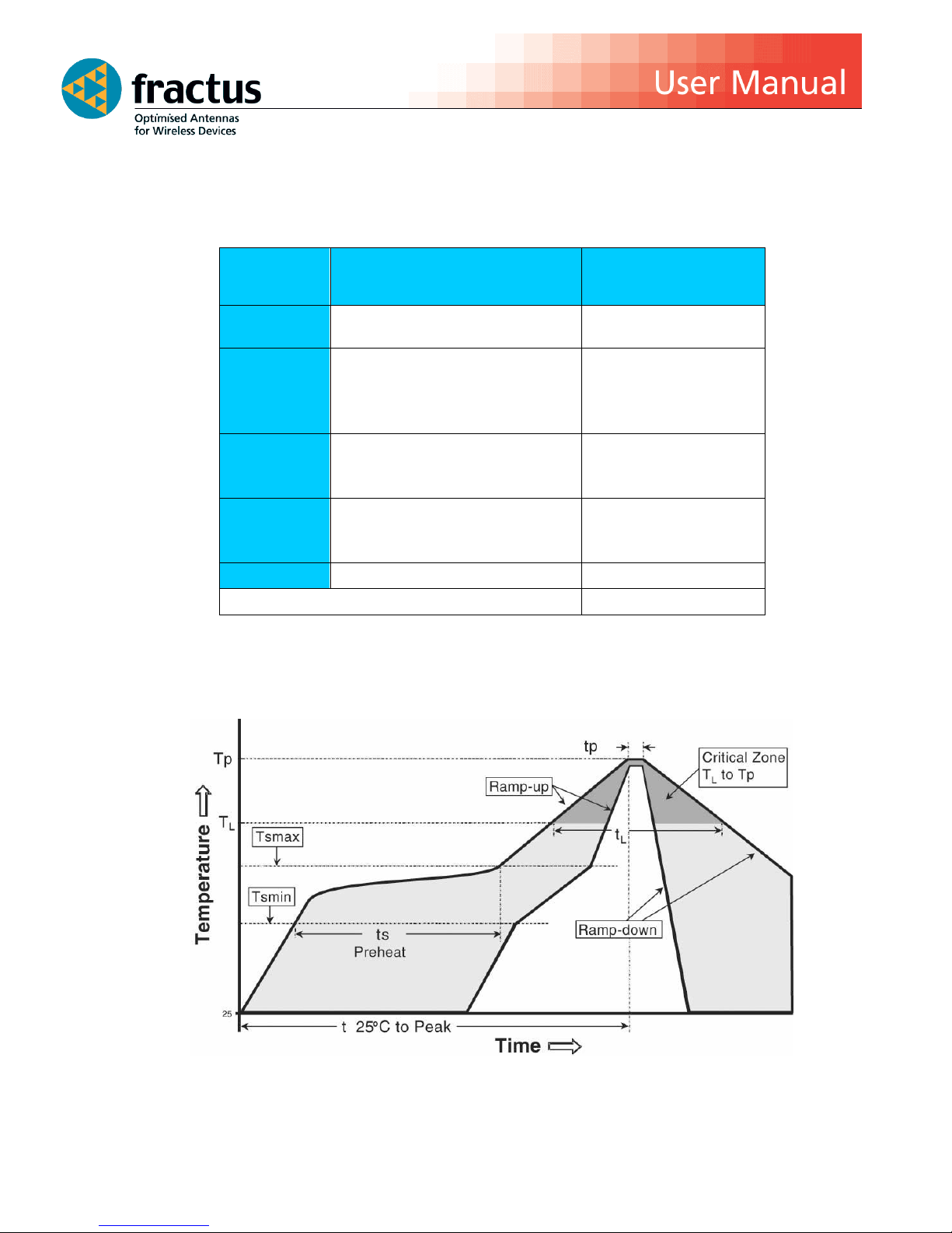
2. Perform a reflow process according to the temperature profile detailed in Table 3, Figure 5 on page 9.
3. After soldering the antenna to the circuit board, perform a cleaning process to remove any residual
flux. Fractus recommends conducting a visual inspection after the cleaning process to verify that all
reflux has been removed.
The drawing below shows the soldering details obtained after a correct assembly process:
Figure 4 - Soldering Details
NOTE: Solder paste thickness after the assembly process will depend on the thickness of the soldering stencil
mask. A stencil thickness equal to or larger than 127 microns (5 mils) is required.
Mounting Pads (2, 3, 4, 5): solder the antenna mounting pads to the
soldering pads on the PCB. These pads must NOT be grounded.
Feed Pad (1): align the feed point with the feeding line on the PCB.
Antenna
PCB
Solder Paste
Antenna
PCB
~ 0.1* mm
1 2 3 4 5
Page 9
February 2013
Page 9
1999-2013 © FRACTUS, S.A.
The TVNowTM dual band (UHF+Lband) DVB-H antenna should be assembled following either Sn-Pb or Pb-free
assembly processes. According to the Standard IPC/JEDEC J-STD-020C, the temperature profile suggested
is as follows:
Phase
Profile features
Pb-Free Assembly
(SnAgCu)
RAMP-UP
Avg. Ramp-up Rate (Tsmax to Tp)
3 ºC / second (max.)
PREHEAT
- Temperature Min (Tsmin)
- Temperature Max (Tsmax)
- Time (tsmin to tsmax)
150 ºC
200 ºC
60-180 seconds
REFLOW
- Temperature (TL)
- Total Time above TL (t L)
217 ºC
60-150 seconds
PEAK
- Temperature (Tp)
- Time (tp)
260 ºC
20-40 seconds
RAMP-DOWN
Rate
6 ºC/second max.
Time from 25 ºC to Peak Temperature
8 minutes max.
Table 3 – Recommended soldering temperatures
Next graphic shows temperature profile (grey zone) for the antenna assembly process in reflow ovens.
Figure 5 – Temperature profile
Page 10
February 2013
Page 10
1999-2013 © FRACTUS, S.A.
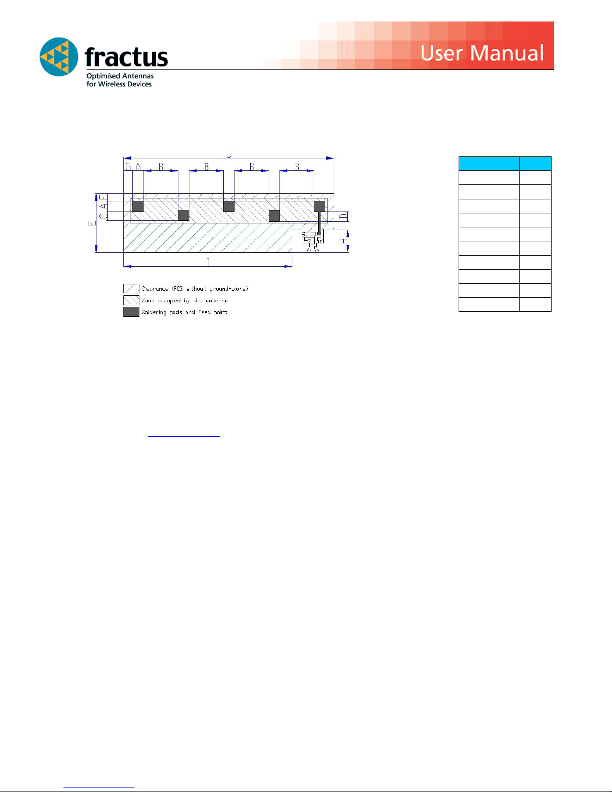
6. ANTENNA FOOTPRINT (as used in the evaluation board)
This antenna footprint applies for the reference evaluation board described on page 4 of this User Manual.
Figure 6 – Antenna Footprint Details
Other PCB form factors and configurations may require a different feeding configuration, feeding line
dimensions and clearance areas. If you require support for the integration of the antenna in your design,
please contact [email protected]
Measure
mm
A
2.0 B 7.0
C
1.8 D 2.0
E
12.0
F
1.5 G 1.9
H
4.7 I 34.2
J
42.7
Tolerance: ±0.2 mm
Note: all the soldering pads
(feed point and mounting
pads) on the antenna layout
have the same dimensions.
 Loading...