

OWNER’S MANUAL
MARK II
Firmware Version 2.15

WARNING: To reduce the risk of fire or electric shock, do not
expose this appliance to rain or moisture.
CAUTION: To reduce the risk of fire or electric shock, do not
remove screws. There are no user serviceable parts inside.
Refer servicing to qualified service personnel.
Legal Notices
Fractal Audio Systems MFC-101 Mark II Owner’s Manual. Contents Copyright © 2010 -2012. All Rights Reserved.
No part of this publication may be reproduced in any form without the permission of Fractal Audio Systems.
Fractal Audio Systems, Axe-Fx, Axe-Fx II, MFC-101 are trademarks of Fractal Audio Systems. Manufacturer names
and product names mentioned herein are trademarks or registered trademarks of their respective owners, which
are in no way associated with or affiliated with Fractal Audio Systems. The names are used only to illustrate sonic
and performance characteristics.
Important Safety Instructions
1. Obey all warnings on the MFC-101 and in this User Guide.
2. Keep away from sources of heat such as heat ducts, registers or appliances which
produce heat.
3. Connect only to a proper AC outlet of 100–240V, 47–63 Hz.
4. Keep the AC adapter in good condition. Do not kink, bend or pinch. If the AC adapter
becomes damaged, discard and replace it.
5. If not using your MFC101 for extended periods of time disconnect from AC mains.
6. Protect the unit from rain and excessive moisture.
7. Refer servicing to qualified personnel only.
8. Do not operate the unit and obtain service if:
a. Liquids or excessive moisture enter the unit
b. The unit operates incorrectly or performance is inconsistent or erratic
c. The unit has been dropped and/or the enclosure damaged
9. Prolonged exposure to high volume levels can cause hearing damage and/or loss. The
use of hearing protection in high volume situations is recommended.
Doc v2.15
Doc v2.15 i

Certificate of Conformity
EN60065
(IEC 60065)
Safety requirement for mains operated electronic and related apparatus for household and similar
use.
EN 55103-1
Product family standard for audio, video, audio-visual and entertainment lighting control apparatus
for professional use. Part 1: Emission.
EN 55103-2
Product family standard for audio, video, audio-visual and entertainment lighting control apparatus
for professional use. Part 2: Immunity.
Fractal Audio Systems, USA, hereby declares on its own responsibility that the following product
MFC101 – MIDI Foot Controller
that is covered by this certificate and marked with CE label conforms to following standards:
with reference to regulations in following directives: 73/23/EEC, 89/336/EEC.
Issued in August 2010
Clifford Chase, President
Fractal Audio Systems
EMC / EMI
This equipment has been tested and found to comply with the limits for a Class B Digital device, pursuant to part 15 of the FCC
rules. These limits are designed to provide reasonable protection against harmful interference in residential installations. This
equipment generates, uses and can radiate radio frequency energy and, if not installed and used in accordance with the
instructions, may cause harmful interference to radio communications. There is no guarantee that interference will not occur in
a particular installation. If this equipment does cause harmful interference to radio or television reception, which can be
determined by turning the equipment off and on, the user is encouraged to try to correct the interference by one or more of
the following measures:
Reorient or relocate the receiving antenna.
Increase the separation between the equipment and receiver.
Connect the equipment to an outlet on a circuit different from that to which the receiver is connected.
Consult the dealer or an experienced radio/TV technician for help.
About the Author
Matt Picone is a music technology product specialist, sound designer, creative director, and musician with over 25 years of
experience spanning guitars, amps, effects, synthesizers, software, and beyond. He has worked with many greats including
Dweezil Zappa, Adrian Belew, Steve Vai, Dream Theater, the Edge, Peter Frampton, Neal Schon, King’s X, Scott Appleton (Def
Leppard/Rush/etc.) and more.
Many thanks to our team of awesome beta-testers, preset creators, copy-editors and proofreaders.
You may report manual corrections or suggestions in our forum at http://forum.fractalaudio.com

Foreword
Thank you for your purchase of the Fractal Audio Systems MFC-101.
Musical instrument foot control dates back to the 1200s, when organ pedals
doubled the number of limbs which could be used by a single person during a
performance. Centuries later, electric instruments were equipped with various
types of foot control devices designed to similarly enhance their capabilities. At
the touch of a switch or pedal, performers could spin, switch, or shape sound in
new and exciting ways. Advances in electronics added new dimensions, and MIDI
tremendously expanded creative remote control with complex commands and
fine degrees of expression.
Just as the Axe-Fx represents a leap forward in music technology, so too does the
MFC-101 embody foot controller evolution. It has the best features of yesterday
and today, plus powerful leading-edge capabilities designed to make it even more
versatile and easy-to-use. In addition, the upgradable firmware and onboard
expansion port ensure that the Fractal Audio Systems tradition of adding
enhancements and value may be continued with the MFC-101.
Whether you pair it with the Axe-Fx or another MIDI product, we hope you enjoy
using the MFC-101 as much as we have enjoyed creating it. We worked hard to
design a product we hope you will think is the ultimate MIDI Foot Controller, and
we’re very much looking forward to seeing it become a favorite on the world
stage.
—Fractal Audio Systems, August 2010
Doc v2.15 iii

CONTENTS Fractal Audio Systems MFC-101 Manual
Table of Contents
Foreword .......................................................................................... iii
Table of Contents .............................................................................. iv
1 OVERVIEW ....................................................................................1
1.1 Main Features .......................................................................................... 1
1.2 Hardware Overview ................................................................................. 2
1.2.1 Footswitch Primary Functions ............................................................................................................... 2
1.2.2 Footswitch Secondary Functions ........................................................................................................... 3
1.2.3 Rear Panel Features ............................................................................................................................... 4
1.3 Software Map .......................................................................................... 5
1.4 Navigating in Edit Mode ........................................................................... 6
1.5 Saving Changes ........................................................................................ 6
2 GETTING CONNECTED ....................................................................7
3 BASIC SETTINGS ........................................................................... 10
3.1 Axe-Fx Mode .......................................................................................... 10
3.1.1 Enabling/Disabling Axe-Fx Mode ......................................................................................................... 10
3.2 Selecting a Port ...................................................................................... 11
3.3 Axe-Fx MIDI Channel .............................................................................. 11
3.4 Display Offset ......................................................................................... 11
3.5 Performance Modes ............................................................................... 13
3.6 Starting Up ............................................................................................. 14
4 PRESETS & PRESET MODE ............................................................ 15
4.1 Bank Size ................................................................................................ 15
4.2 Bank Style .............................................................................................. 16
4.3 Presets and Program Changes ................................................................ 16
4.4 Other Preset Capabilities ........................................................................ 16

Fractal Audio Systems MFC-101 Manual CONTENTS
4.5 Alternate Presets ................................................................................... 17
4.5.1 Global Preset ........................................................................................................................................ 18
5 INSTANT ACCESS SWITCHES ......................................................... 19
5.1 Axe-Fx IA Switches ................................................................................. 19
5.1.1 List of Available Axe-Fx Functions ........................................................................................................ 20
5.1.2 Axe-Fx IA Switch On/Off States ............................................................................................................ 21
5.1.3 “General Use” IA Switches in Axe-Fx mode ......................................................................................... 21
5.1.4 Axe-Fx I/O:CONTROL Settings .............................................................................................................. 21
5.1.5 Axe-Fx Tap Tempo ............................................................................................................................... 21
5.1.6 Axe-Fx Tuner ........................................................................................................................................ 21
5.2 General Use IA Switches ......................................................................... 22
5.2.1 General Use IA Switch Control Change Messages ............................................................................... 22
5.2.2 Other General Use IA Switch Capabilities ............................................................................................ 23
5.2.3 General Use IA Switch Saved States .................................................................................................... 23
5.2.4 Global General Use Instant Access Switches ....................................................................................... 24
5.2.5 “Manual-Only” General Use Instant Access Switches ......................................................................... 25
5.2.6 The Save Edits Footswitch ................................................................................................................... 26
5.3 IA Switch Types ...................................................................................... 26
5.4 Switch Links ........................................................................................... 27
5.5 Reveal .................................................................................................... 27
6 INTERNAL CCs .............................................................................. 28
6.1 Internal CC MIDI commands ................................................................... 28
6.2 Preset Internal CC States ........................................................................ 29
7 EXPRESSION PEDALS .................................................................... 30
7.1 Connecting and Calibrating .................................................................... 30
7.2 Expression Pedal MIDI Functions ............................................................ 30
7.3 Expression Pedal Range .......................................................................... 31
8 EXTERNAL SWITCHES ................................................................... 32
8.1 Setting Switch Hardware Types .............................................................. 32
8.2 External Switch MIDI Functions .............................................................. 33
Doc v2.15 v

CONTENTS Fractal Audio Systems MFC-101 Manual
8.3 External Switch Custom On and Off Values ............................................ 34
9 SONGS & SETS ............................................................................. 35
9.1 Entering Song or Set Mode ..................................................................... 35
9.2 Adding Presets to a Song ........................................................................ 36
9.3 Adding Songs to a Set ............................................................................. 37
10 COPY FUNCTIONS ...................................................................... 38
11 NAMES ..................................................................................... 39
12 COMPLETE MENU REFERENCE ................................................... 40
12.1 The Preset Menu ................................................................................. 41
12.1.0 Select Preset ........................................................................................................................................ 41
12.1.1 Preset Name ........................................................................................................................................ 41
12.1.2 Preset Program Changes ...................................................................................................................... 42
12.1.3 Alternate Preset ................................................................................................................................... 42
12.1.4 Preset Instant Access Switch States ..................................................................................................... 43
12.1.5 Preset Internal Control Change States ................................................................................................. 43
12.1.6 Preset Custom MIDI Message .............................................................................................................. 44
12.1.7 Preset External Switch Settings ........................................................................................................... 45
12.1.8 Preset External Switch On/Off Values ................................................................................................. 45
12.1.9 Preset Expression Pedal Settings ......................................................................................................... 46
12.1.10 Preset Expression Pedal Min/Max Values........................................................................................ 46
12.2 The Song/Set Menu ............................................................................. 47
12.2.0 Song Edit .............................................................................................................................................. 47
12.2.1 Song Name ........................................................................................................................................... 47
12.2.2 Set Edit ................................................................................................................................................. 48
12.2.3 Set Name.............................................................................................................................................. 48
12.3 The Copy Menu ................................................................................... 49
12.3.0 Copy Preset .......................................................................................................................................... 49
12.3.1 Copy Bank ............................................................................................................................................ 49
12.3.2 Copy Song ............................................................................................................................................ 50
12.3.3 Copy Set ............................................................................................................................................... 50
12.3.4 Copy Instant Access Switch Setting ..................................................................................................... 50
12.3.5 Copy Internal Control Change Setting ................................................................................................. 50

Fractal Audio Systems MFC-101 Manual CONTENTS
12.4 The MIDI Menu ................................................................................... 51
12.4.0 MFC-101 Port ....................................................................................................................................... 51
12.4.1 Axe-Fx MIDI Channel ............................................................................................................................ 51
12.4.2 Axe-Fx TotalSync .................................................................................................................................. 51
12.4.3 Axe-Fx Preset Transmit Map ................................................................................................................ 52
12.4.4 MFC-101 MIDI Receive Channel .......................................................................................................... 52
12.4.5 MFC-101 Receive Program Change ...................................................................................................... 52
12.4.6 MFC-101 Program Change Map ........................................................................................................... 52
12.4.7 IA Switch Axe-Fx Functions .................................................................................................................. 53
12.4.8 IA Switch Control Change (CC#) Settings ............................................................................................. 53
12.4.9 IA Switch Control Change ON/OFF Values ........................................................................................... 54
12.4.10 IA Switch Program Change Settings ................................................................................................. 54
12.4.11 IA Switch Custom MIDI Messages .................................................................................................... 55
12.4.12 Internal Control Change Settings ..................................................................................................... 56
12.4.13 Internal Control Change ON/OFF Values ......................................................................................... 56
12.4.14 Global External Switch Settings ....................................................................................................... 57
12.4.15 Global External Switch On/Off Values ............................................................................................. 57
12.4.16 Global Expression Pedal Settings ..................................................................................................... 58
12.4.17 Global Expression Pedal Min/Max Values ....................................................................................... 58
12.5 The Setup Menu .................................................................................. 59
12.5.0 Axe-Fx Mode ........................................................................................................................................ 59
12.5.1 Performance Mode .............................................................................................................................. 59
12.5.2 Axe-Fx Display Offset ........................................................................................................................... 59
12.5.3 MFC-101 Display Offset ....................................................................................................................... 60
12.5.4 MIDI Channel Display Offsets .............................................................................................................. 60
12.5.5 MIDI Channel Names ........................................................................................................................... 60
12.5.6 Bank Size .............................................................................................................................................. 61
12.5.7 Bank Style ............................................................................................................................................ 61
12.5.8 Bank/Song Limit ................................................................................................................................... 62
12.5.9 Bank/Song Wrap .................................................................................................................................. 62
12.5.10 IA Switch Types ................................................................................................................................ 63
12.5.11 Global IA Switch Setup ..................................................................................................................... 63
12.5.12 IA Switch Send w/ Preset ................................................................................................................. 63
12.5.13 IA Switch Names .............................................................................................................................. 64
12.5.14 IA Switch Link Settings ..................................................................................................................... 64
12.5.15 Send IA Switch Link OFF Messages .................................................................................................. 65
Doc v2.15 vii

CONTENTS Fractal Audio Systems MFC-101 Manual
12.5.16 Internal CC Names ........................................................................................................................... 65
12.5.17 External Switch Hardware Type ....................................................................................................... 65
12.5.18 Expression Pedal Calibration ............................................................................................................ 66
12.5.19 Global Preset .................................................................................................................................... 66
12.5.20 Hold Axe-Fx Tempo for Tuner .......................................................................................................... 67
12.5.21 Axe-Fx Instant Access Switch LED Off State ..................................................................................... 67
12.5.22 Save Edits Switch ............................................................................................................................. 67
12.5.23 Edit Menu Short/Long ...................................................................................................................... 67
12.5.24 Looper Control ................................................................................................................................. 68
12.5.25 SysEx Data Dump/Load .................................................................................................................... 68
12.5.26 Delete and Reset Factory Settings ................................................................................................... 69
12.5.27 Display Contrast ............................................................................................................................... 70
12.5.28 Firmware Information ...................................................................................................................... 70
13 SYSTEM FUNCTIONS .................................................................. 71
13.1 Firmware Upgrade ............................................................................... 71
13.2 Factory Default Settings Reset ............................................................. 71
14 APPENDIX ................................................................................. 72
14.1 Comparison Table: Axe-Fx Mode ON vs. OFF ....................................... 72
14.2 Firmware Update Error Codes ............................................................. 73
14.3 Axe-Fx Presets Bank & Program Change Table ..................................... 74
14.4 Custom MIDI Message Primer ............................................................. 75
14.4.1 Program Change .................................................................................................................................. 75
14.4.2 Control Change .................................................................................................................................... 76
14.4.3 System Exclusive .................................................................................................................................. 76
14.4.4 Custom MIDI Message Example .......................................................................................................... 76
14.5 Axe-Fx II Looper Control Mode ............................................................ 77
15 Specifications ............................................................................ 78
15.1 Factory Default Settings ...................................................................... 79
15.2 Midi Implementation Chart ................................................................. 81
16 Index ........................................................................................ 82
17 Warranty .................................................................................. 83

Fractal Audio Systems MFC-101 Manual CONTENTS
TABLE OF FIGURES
Figure 1-1: The Default Layout of the MFC-101 ............................................................................................................ 1
Figure 1-2: The MFC-101 Top Panel............................................................................................................................... 2
Figure 1-3: Layout of an MFC-101 Footswitch ............................................................................................................... 3
Figure 1-4: MFC-101 Mk II Rear Panel Diagram ............................................................................................................. 4
Figure 1-5: Software Map .............................................................................................................................................. 5
Figure 1-6: Navigating Edit mode .................................................................................................................................. 6
Figure 2-1: Connecting the MFC-101 to an Axe-Fx II ..................................................................................................... 7
Figure 2-2: Connecting the MFC-101 to an Axe-Fx with Phantom Power ................................................................... 8
Figure 2-3: Connecting the MFC-101 to an Axe-Fx without Phantom Power................................................................ 8
Figure 2-4: Connecting the MFC-101 to a 3rd Party MIDI module or processor (Axe-Fx Mode OFF) ........................... 9
Figure 2-5: Connecting the MFC-101 to an Axe-Fx and Additional MIDI device(s) ....................................................... 9
Figure 4-1: Bank Sizes/Footswitch Layout Examples ................................................................................................... 15
Figure 5-1: Default IA Switch Assignments in Axe-Fx Mode. ....................................................................................... 19
Figure 5-2: Default Control Change Assignments for General Use IA Switches. ......................................................... 22
Figure 7-1: TRS Cable, AKA “Balanced” or “Stereo” Cable End. .................................................................................. 30
Figure 8-1: External Switch Appearance on Insert Cable Plugs ................................................................................... 32
Figure 14-1: Looper Control Mode Footswitch Functions ........................................................................................... 77
Doc v2.15 ix


Fractal Audio Systems MFC-101 Manual OVERVIEW
1 OVERVIEW
1.1 Main Features
The Fractal Audio Systems MFC-101 is a powerful, versatile, easy-to-use MIDI foot controller designed for use with
the Fractal Audio Systems Axe-Fx Standard, Ultra, or Axe-Fx II and/or any other MIDI devices such as modules,
amps, effects, synths, and more. It is built with the professional musician in mind and features a rugged 16-gauge
powder-coated steel chassis, 21 heavy-duty “Carling style” footswitches, a brilliant 20-character transflective
display, 21 dual-color LEDs, jacks for 4 expression pedal and 4 external switches, an expansion port, plus the
performance control features that musicians have come to demand from a best-in-class controller. In AXE-FX
MODE, the MFC-101 offers the easiest way available to control your Axe-Fx, offering hassle-free integration of
preset names, intelligent control over effect bypass switching, integrated tap tempo and tuner, and more.
MFC-101 FEATURE HIGHLIGHTS
Simple to set up and use, but powerful and flexible enough to control complex rigs.
PRESET, SONG, and SET MODES are well-suited for a range of performance settings.
The onboard memory stores 384 Presets, 100 Songs, and 10 Sets of up to 50 Songs each.
You can globally designate any number of footswitches for selecting PRESETS, each of which sends:
Up to 16 MIDI program change messages (one per channel).
ON or OFF messages for up to 17 Instant Access Switches.
ON or OFF messages for up to 17 Internal Control Change (“CC”) messages.
Up to 16 bytes of custom MIDI data. Anything goes!
Those footswitches not assigned to Presets operate as INSTANT ACCESS (“IA”) SWITCHES:
Axe-Fx functions may be assigned to IA Switches simply by selecting from a list.
“General Use” IA Switches (i.e. those not assigned to Axe-Fx functions) have independent ON
and OFF command sets, each with:
o Up to two CC# messages with custom values
o One MIDI program change command
o Up to 16 bytes of custom MIDI data. Anything goes!
IA Switches may be set for Toggle (aka “Latching”) , Momentary (“Hold”) or “Auto-Off” function.
REVEAL mode temporarily toggles Preset footswitches to their “hidden” Instant Access functions.
Axe-Fx LOOPER CONTROL MODE gives access to all Looper functions with no programming required.
Full support for Axe-Fx II SCENES
Future enhancement and improvement made possible via user-upgradeable firmware capability.
Support for Phantom Power over 7-pin, plus bidirectional Axe-Fx MIDI data over a single cable.
And more!
Figure 1-1: The Default Layout of the MFC-101
Doc v2.15 1
OVERVIEW Fractal Audio Systems MFC-101 Manual
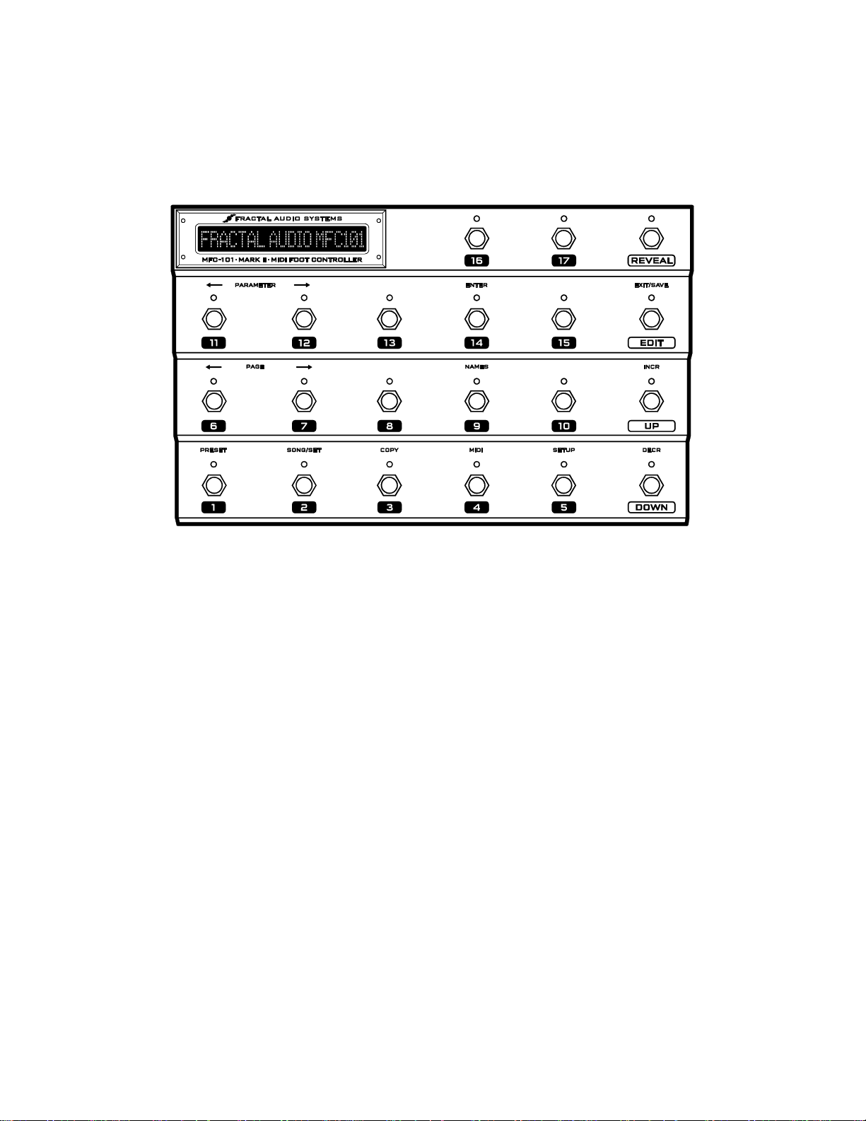
1.2 Hardware Overview
The MFC-101 has 21 heavy-duty multi-purpose footswitches with bi-color LEDs. The display is a 1×20 character,
bright green, transflective LCD that offers great visibility anywhere from total darkness to bright daylight.
Figure 1-2: The MFC-101 Top Panel
1.2.1 Footswitch Primary Functions
The footswitches perform their primary functions whenever the MFC-101 is not in EDIT MODE for programming.
Footswitches 1-17 may be used to select Presets, or as Instant Access Switches (“IA”) controlling
effects or other functions of a MIDI device. The division of the 17 footswitches between Preset and IA
functions is determined by the global Bank Size setting (p.15). The factory default is for switches 1–5
to select presets while 6–17 to operate as IA Switches.
REVEAL: Preset footswitches also have hidden Instant Access Switch functions which become
accessible when Reveal is tapped ON. When Reveal is toggled OFF, footswitches revert to their usual
preset functions. See p. 27 for more information on Reveal. In Axe-Fx Mode (p. 10) pressing and
holding the REVEAL footswitch will enter LOOPER CONTROL MODE (p. ).
EDIT: This switch puts the MFC-101 into EDIT MODE, allowing entry to the various menus, pages and
parameters used to configure the unit. From EDIT MODE, press EDIT again to return to play mode.
SAVE (also on the EDIT footswitch) is used to store MFC-101 presets on-the-fly after changing the
states of “general purpose” Instant Access Switches (i.e., those not set for Axe-Fx functions, which are
always read directly from the Axe-Fx as presets are loaded). If the SAVE EDITS feature (p. 67) is
enabled, the Save footswitch LED will flash when IA switch states are changed. Pressing it will store
the MFC-101 preset.
UP and DOWN are used to select the next or previous Bank or Song.
Fractal Audio Systems MFC-101 Manual OVERVIEW
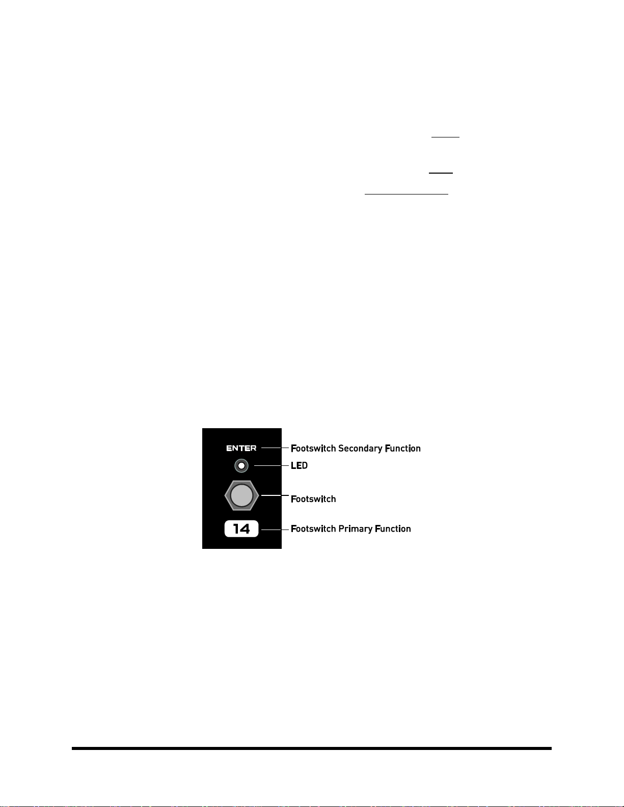
1.2.2 Footswitch Secondary Functions
The footswitches perform their secondary functions when the MFC-101 is in EDIT MODE:
After EDIT is pressed once, footswitches 1–5 are used to enter the 5 main menus:
PRESET, SONG/SET, COPY, MIDI, and SETUP.
The two PAGE footswitches (6 & 7) step back and forth through the pages of the current menu.
The two PARAMETER footswitches (11 & 12) select editable parameters on the current page.
The (INCRement and DECRement footswitches (UP and DOWN) change the value of the currently
selected parameter.
You can hold any of the above to scroll quickly through the list of pages/parameters/values.
ENTER (footswitch 14) is used to execute various functions. Examples include Factory Restore or
Dump to SysEx. The LED above this footswitch flashes red when ENTER can be used to perform some
action, and to remind you that this will be committed to memory immediately with no turning back.
EXIT is the secondary function of the EDIT footswitch. Pressing this footswitch while in in EDIT MODE
will save all changes and return the MFC-101 to PERFORMANCE MODE.
NAMES (footswitch 9) makes it easier to customize your MFC-101 for easy operation. It allows you to
view the short NAMES you may assign to various items throughout the the memory of the MFC-101. A
MIDI Channel, for example, might be named “Gizmo” or an Instant Access Switch might be named
“Extern 8”. See Chapter 11 for details on how to enter names.
Figure 1-3: Layout of an MFC-101 Footswitch
Doc v2.15 3
OVERVIEW Fractal Audio Systems MFC-101 Manual
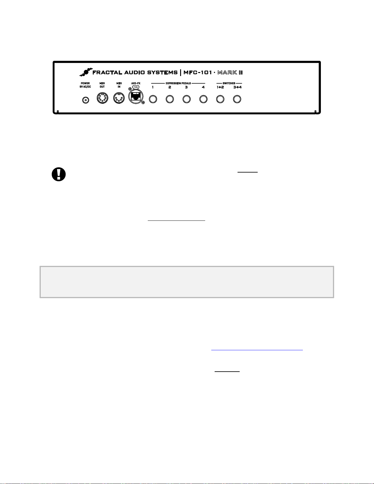
1.2.3 Rear Panel Features
Figure 1-4: MFC-101 Mk II Rear Panel Diagram
POWER 9VAC: Plug the supplied AC adapter into this jack. If you are using an Axe-Fx or other device to
supply phantom power to the MFC-101 over a 7-pin MIDI cable, you must instead connect the
supplied AC adapter to the Phantom Power jack of that device.
When using a CAT5 cable to connect the MFC-101 to an Axe-Fx II, DO NOT connect the MFC-101 AC
Adapter to the MFC-101 power jack or the Phantom Power jack of the Axe-Fx II or you may damage
one or both products. The AC Adapter is NOT USED when connecting via CAT5 to an Axe-Fx II. The
CAT5 cable provides power from the Axe-Fx II power supply to the MFC-101 Expansion Port.
MIDI OUT: This 7-pin jack is a regular MIDI OUT port for connecting to any MIDI device. Any Axe-Fx will
be able to utilize this port for 2-way communications so the MFC-101 can send and receive data over a
single cable. Some devices, including the Axe-Fx, can also supply phantom power to the MFC-101 via a
7-pin cable connected here. See Getting Connected on p. 7.
The MIDI IN port is used for firmware updates, for remote controlling the MFC-101, or for 2-way
communications with an Axe-Fx when a single MIDI cable does not work.
IMPORTANT! When connecting a device to remote control the MFC-101, remember that the Axe-Fx also transmits data to the
unit via the bi-directional MIDI out port. Plan and test carefully as unpredictable behavior may occur in a rig where more than
one device is trying to control the MFC-101.
AXE-FX: This jack can be used to connect an Axe-Fx II. Use standard Ethernet cable (not crossover
type) with or without EtherCON endplugs. EtherCONs are ruggedized RJ45 connectors which provide
added stability and protection to prevent cable strain or jolts from causing damage to connectors
and/or ports. If possible, use an EtherCON cable with your Mark II products.
High quality Ethernet/Ethercon cables are available via http://www.fractalaudio.com/cables
EXPRESSION PEDAL JACKS 1–4: These jacks allow you to connect up to 4 optional expression
pedals using 1/4" TRS cables. Expression pedals must be calibrated before they will work properly.
See EXPRESSION PEDALS on p. 30 for details.
EXTERNAL SWITCH JACKS 1+2, 3+4: Each of these TRS jacks allows you to connect one or two
external switches. The first switch on each jack operates on the tip-to-sleeve connection, while the
second is on ring-to-sleeve. Either jack may also be used with a single footswitch connected via a TipSleeve cable, but it is recommended that you disable the MIDI functions of the jack’s second switch
when operating in this way (See p. 57). Both toggle and momentary switch hardware is supported.
See EXTERNAL SWITCHES on p. 32 for details.
Fractal Audio Systems MFC-101 Manual OVERVIEW
• Select Preset
• Preset Name
• Preset Program Changes
• Alternate Preset
• Preset IA Switch States
• Preset Internal CC States
• Preset Custom MIDI Msg.
• Preset Ext. Switch Settings
• Preset Ext. Sw. On/Off Vals.
• Preset Exp. Pdl. Settings
• Preset Exp. Pdl. Min/Max
• Song Edit
• Song Name
• Set Edit
• Set Name
• Copy Preset
• Copy Bank
• Copy Song
• Copy Set
• Copy IA Switch
• Copy Internal CC
• Use Port
• Axe-Fx MIDI Channel
• Axe-Fx TotalSync
• Axe-Fx Preset Tx Map
• MFC MIDI Rx Channel
• MFC Rx Program Change
• MFC Prog. Change Map
• IA Axe-Fx Function
• IA CC# Settings
• IA CC# On/Off Values
• IA Program Changes
• IA Custom MIDI Msgs.
• Internal CC Settings
• Internal CC On/Off Vals.
• Global Ext. Switch Setup
• Global Ext. Sw. On/Off Vals.
• Global Exp. Pedal Setup
• Global Exp. Min/Max Vals
• Axe-Fx Mode
• Performance Mode
• Axe-Fx Display Offset
• MFC-101 Display Offset
• MIDI Ch. Display Offsets
• MIDI Ch. Names
• Bank Size
• Bank Style
• Bank/Song Limit
• Bank Song/Wrap
• IA Switch Types
• Global IA Switches
• IA Send w/ Preset
• IA Switch Names
• IA Switch Link Settings
• Send Sw. Link OFF Msgs.
• Internal CC Names
• Ext. Switch HW Types
• Exp. Pedal Calibrate
• Global Preset
• Hold Axe Tempo = Tune
• IA Off LED red/off
• Save Edits Switch
• Edit Menu Short/Long
• Looper Control
• SysEx Data Dump/Load
• Delete/Factory Reset
• Display Contrast
• Firmware Info
The footswitch for the currently selected menu returns to the top level of the EDIT menu.
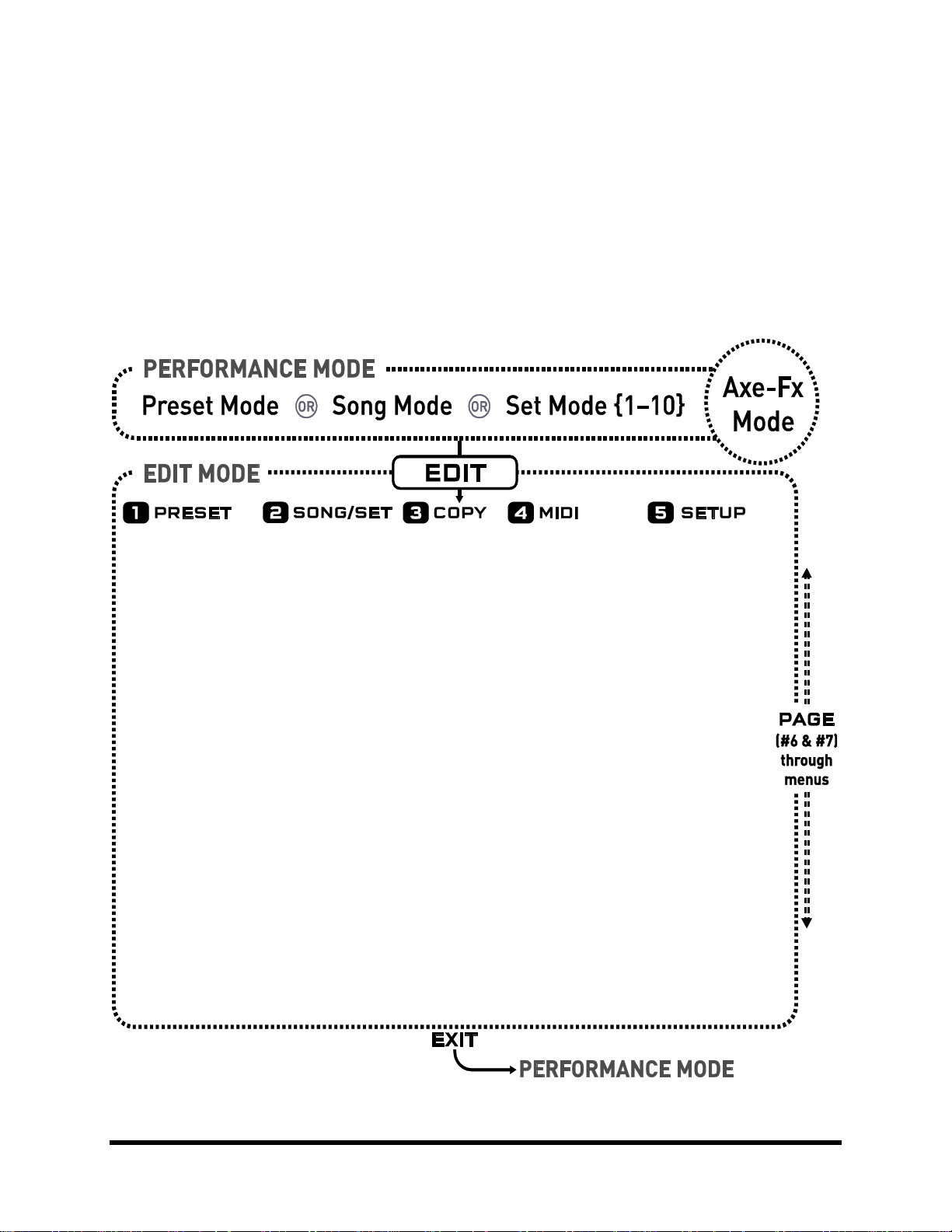
1.3 Software Map
PERFORMANCE MODE is for normal use, where the MFC-101 is operated as a MIDI foot controller. Depending on
the desired use, there are three variants: PRESET, SONG or SET MODE, covered later. AXE-FX MODE may be
switched ON or OFF “on top” of the above modes to provide enhanced Axe-Fx control.
EDIT MODE is separate from PERFORMANCE MODE and is used to access to the MENUS which are used to
configure the MFC-101. These menus are numbered 1 –5 below for the footswitches which access them. Each
menu contains a number of PAGES (listed below in columns). Each page has one or more parameters detailed
throughout this manual.
Doc v2.15 5
Figure 1-5: Software Map
OVERVIEW Fractal Audio Systems MFC-101 Manual
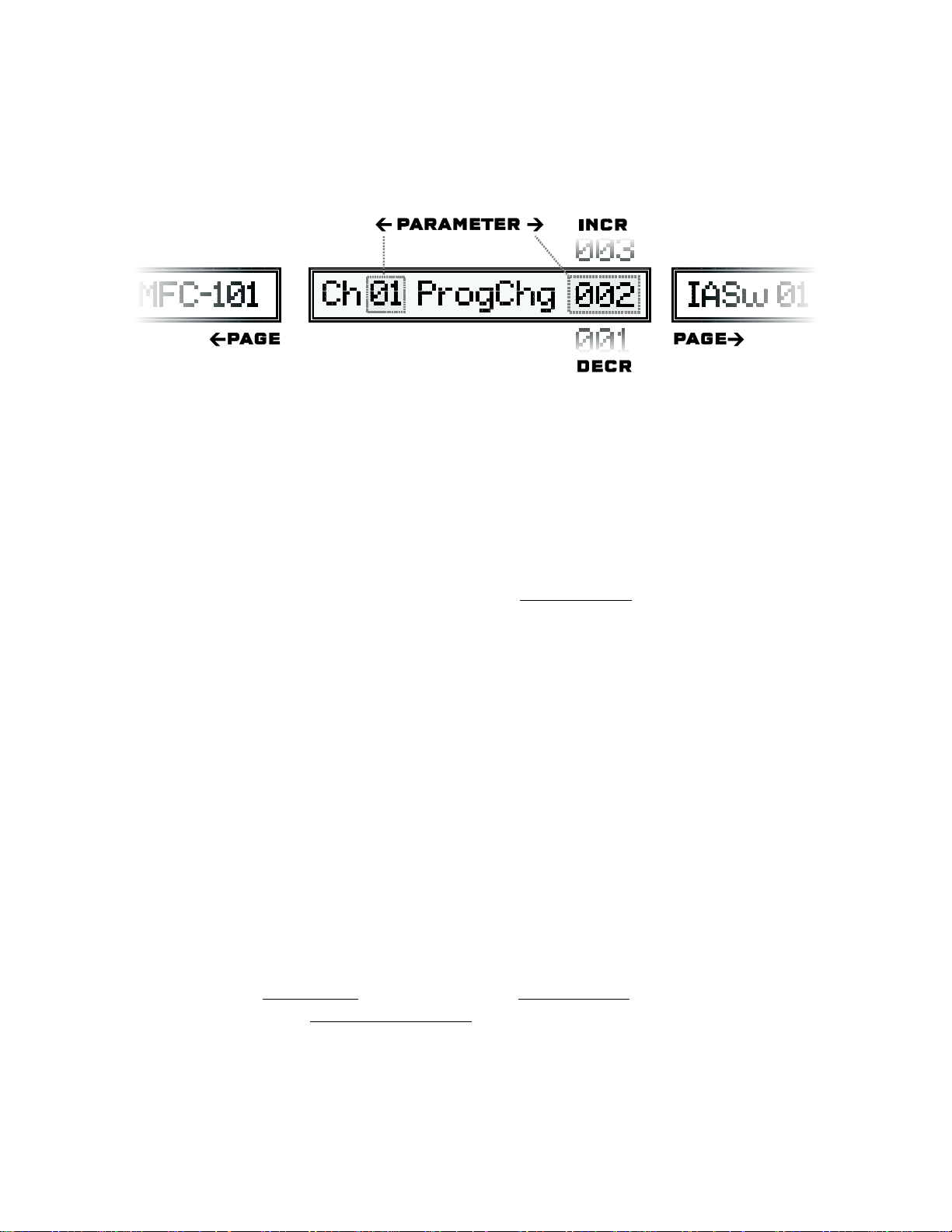
1.4 Navigating in Edit Mode
The footswitches are used to navigate the menus, pages and parameters of EDIT MODE.
Figure 1-6: Navigating Edit mode
To enter EDIT MODE, press EDIT.
Press any of the menu footswitches (1–5) to open a menu.
Each menu has multiple pages. The PAGE footswitches move between these.
Each page has from 1 to 4 parameters. The PARAMETER footswitches move between these. The
currently selected parameter will have an underline beneath the first character of its value.
The INCR/DECR footswitches scroll through the available values for each parameter.
Most parameters are programmable. A few, such as Firmware Version are purely informational and
can be displayed but not edited.
All navigation, whether through pages, parameters, or values, will “wrap”, meaning whether you use
INCR or DECR you will ultimately reach the desired value.
Footswitches may be pressed and then held down to advance rapidly through a series.
The ENTER footswitch (#14) is sometimes required to activate special functions.
This is indicated by a blinking LED above the ENTER footswitch.
1.5 Saving Changes
The MFC-101 was designed to save changes automatically while you navigate.
Pressing either PAGE footswitch will save changes.
Pressing the EXIT footswitch will save changes and return to PERFORMANCE MODE.
Pressing the footswitch for a menu while in that menu will save and return to the top-level menu.
Changing the “index” of a multi-parameter screen will save changes. Examples of index parameters
include the Preset Number in the preset menu, the IA Switch number on a page which edits multiple
IA Switches, or the Expression Pedal Number on a page which edits multiple expression pedals.
To abort edits without saving, simply disconnect power from the MFC-101, wait several seconds, and then
restore power to the unit.
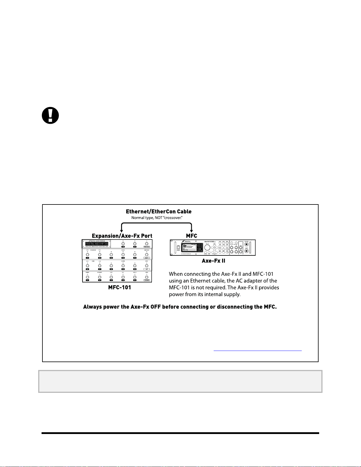
Fractal Audio Systems MFC-101 Manual GETTING CONNECTED
Figure 2-1: Connecting the MFC-101 to an Axe-Fx II
2-way comms and power provided by a single CAT5/Ethernet/EtherCon cable.
MIDI received at the Axe-Fx II MFC port will only be forwarded to the Axe-Fx II MIDI OUT/THRU port
if you set the Axe-Fx II MIDI THRU function to “ON” (in the I/O:MIDI menu of the Axe-Fx II)
Ethernet, EtherCon and other high quality cables available from http://www.fractalaudio.com/cables
2 GETTING CONNECTED
Before making connections, be sure to turn down the volume of your amp and switch off power to all devices.
The MFC-101 supports a number of different setup scenarios. A few common possibilities are diagrammed below.
Ethernet and 7-pin MIDI cables can carry “Phantom Power” to allow faster setups and less clutter on the floor.
AXE-FX MODE (see p. 10) depends on 2-way MIDI communication between the Axe-Fx and the MFC-101.
This is possible over a single Ethernet or 7- or 5-pin MIDI cable due to special features of both devices.
MIDI cables must be wired on ALL PINS for bi-directional communication to work in this way. Because other MIDI
devices often require only 3 pins, some MIDI cables contain 3 rather than 5 wires (or 5 vs. 7). The message “AXE-FX
NAME TIMEOUT” is displayed on the MFC-101 in Axe-Fx mode when 2-way communication cannot be established.
This may indicate improper settings but can also mean that your MIDI cable is not wired on all pins. Use a multimeter to test pin continuity, or try an approved cable from fractalaudio.com/cables
In a pinch, you can actually use Axe-Fx mode with two “inferior” MIDI cables connected In-to-Out and Out-to-In.
The first scenario below shows using the Axe-Fx II and MFC-101 with no midi cables.
IMPORTANT: NEVER connect the provided AC Adapter to the MFC-101 or to the Phantom Power jack of the Axe-Fx II while
the MFC-101 and Axe-Fx II are connected via CAT5. Doing so could damage one or both units.
Doc v2.15 7
GETTING CONNECTED Fractal Audio Systems MFC-101 Manual
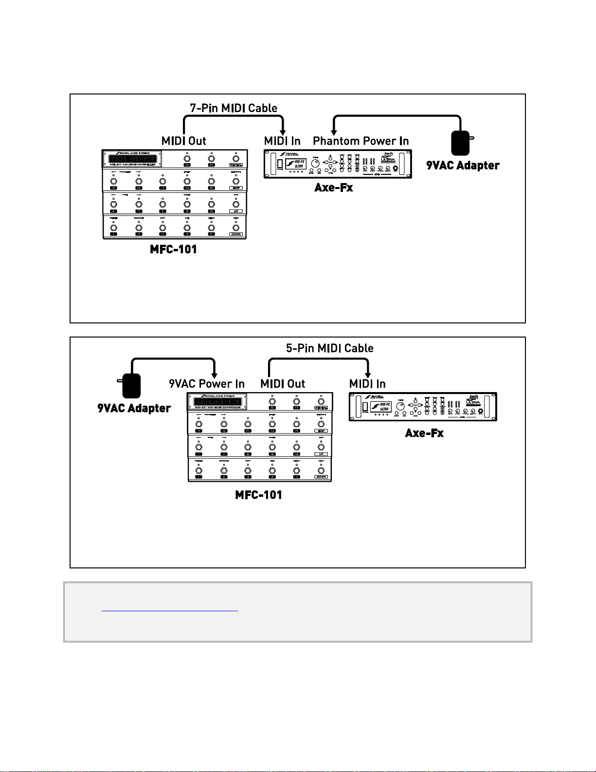
Figure 2-2: Connecting the MFC-101 to an Axe-Fx with Phantom Power
2-way MIDI data communication and phantom power are provided via a single 7-conductor MIDI cable.
The Axe-Fx Standard, Ultra, or Axe-Fx II may be connected in this way.
Figure 2-3: Connecting the MFC-101 to an Axe-Fx without Phantom Power
2-way MIDI data communication is provided via a single 5-conductor MIDI cable.
The Axe-Fx Standard, Ultra, or Axe-Fx II may be connected in this way.
The next scenarios show connections over 7 or 5 pin MIDI cables:
IMPORTANT: Axe-Fx Mode requires Axe-Fx firmware dated AUGUST 2010 or later. Check your unit under UTILITY:FIRMWARE
and visit http://www.fractalaudio.com/support to download a free upgrade if required.
You must manually select MIDI under PORT in the MIDI menu before using MIDI cable connections (AXE-FX is the default)
Fractal Audio Systems MFC-101 Manual GETTING CONNECTED
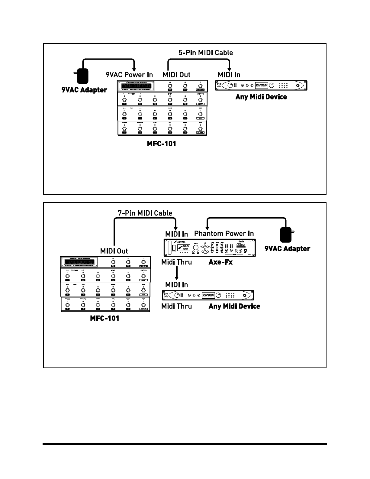
Figure 2-4: Connecting the MFC-101 to a 3rd Party MIDI module or processor (Axe-Fx Mode OFF)
The 5-pin MIDI cable carries 1-way data from the MFC-101 to the connected device.
Some 3rd party devices may also provide 7-pin Phantom Power and can be connected as shown above.
Figure 2-5: Connecting the MFC-101 to an Axe-Fx and Additional MIDI device(s)
2-way MIDI data communication and Phantom over a 7-pin cable for the Axe-Fx.
MIDI THRU passes extra MFC-101 commands to downstream devices.
Doc v2.15 9

BASIC SETTINGS Fractal Audio Systems MFC-101 Manual
1
Axe-Fx Mode II
3 BASIC SETTINGS
3.1 Axe-Fx Mode
AXE-FX MODE makes using the MFC-101 easier and more intuitive. Axe-Fx mode rides on top of PRESET, SONG, or
SET mode to provide a number of benefits when using the MFC-101 with an Axe-Fx II, Ultra, or Standard.
Axe-Fx preset names are displayed dynamically as they load—no need for data entry or import!
Instant Access Switch Axe-Fx Functions can be set simply by selecting from a list.
Instant Access Switch LEDs show the effects in the current Axe-Fx preset when it is loaded:
GREEN: Present & Active; RED: Present & Bypassed1; OFF: Not Present.
The TAP TEMPO footswitch LED flashes the current Axe-Fx tempo.
The TUNER footswitch displays the Axe-Fx tuner in the MFC-101 display.
Preset footswitches can also send general use MIDI commands for controlling bigger rigs.
Individual IA Switches can be set up with general use MIDI commands instead of Axe-Fx functions.
You may wish to refer to p. 72 of the appendix to view the Comparison Table: AXE-FX MODE ON vs. OFF.
3.1.1 Enabling/Disabling Axe-Fx Mode
For Axe-Fx mode to work, you must initially select the Axe-Fx model you are using with the MFC-101. If you are
using the MFC-101 without an Axe-Fx, you should turn Axe-Fx mode OFF.
1. Press EDIT footswitch to enter EDIT MODE
2. Press SETUP footswitch for the SETUP menu to arrive at the AXE-FX MODE screen:
3. Press the INCR or DECR footswitches to select the model of AXE-FX MODEL you are using, (II,
ULTRA, STANDARD) or select OFF to disable Axe-Fx mode.
As of MFC-101 firmware version 2.0, the default is Axe-Fx II.
4. Press EXIT to return to PERFORMANCE MODE.
IMPORTANT: Axe-Fx Mode requires Axe-Fx firmware dated AUGUST 2010 or later. Check your unit under UTILITY:FIRMWARE
and visit http://www.fractalaudio.com/support to download a free upgrade if required.
To improve usability for individuals with red/green colorblindness, red LEDs can be set for “OFF”. See p. 66.
Fractal Audio Systems MFC-101 Manual BASIC SETTINGS
Use Port Expansion
Axe-Fx MIDI Ch 01
Axe-Fx DisplayOfst 0
3.2 Selecting a Port
Depending on whether your Axe-Fx is connected at the AXE-FX port or the MIDI port, you must set the
MFC-101 accordingly. (As of MFC firmware 2.0, the default is AXE-FX).
1. Press EDIT footswitch to enter EDIT MODE.
2. Press MIDI footswitch for the MIDI menu to arrive at the USE PORT screen:
3. Press INCR or DECR to select “MIDI” or “EXPANSION” (the latter for the “Axe-Fx” port).
4. Press EXIT to return to PERFORMANCE MODE.
3.3 Axe-Fx MIDI Channel
A factory-fresh MFC-101 expects the Axe-Fx to be on MIDI channel 1 (the unit’s default setting). If you have
modified this setting in your Axe-Fx, you will need to make the same setting in the MFC-101 for AXE-FX MODE to
work properly:
1. Press EDIT footswitch to enter EDIT MODE.
2. Press MIDI footswitch to select the MIDI menu.
3. Press PAGE once to arrive at the Axe-Fx MIDI Channel Screen:
4. Press the INCR or DECR footswitches to set the desired Midi Channel.
5. Press EXIT to return to PERFORMANCE MODE.
3.4 Display Offset
The Axe-Fx has a “Display Offset” feature which causes its presets to appear to be numbered from 001 instead of
from 000. If you have Display Offset set to “1” on your Axe-Fx, you need to make a setting change on the MFC-101:
1. Press EDIT footswitch to enter EDIT mode.
2. Press SETUP footswitch to select the SETUP menu.
3. Press PAGE 2x to get to the Axe-Fx Display Offset Screen:
4. Press the INCR or DECR footswitch to set Display Offset as desired.
5. Press EXIT to return to PERFORMANCE MODE.
Doc v2.15 11

BASIC SETTINGS Fractal Audio Systems MFC-101 Manual
MFC DisplayOfst 0
In addition, you will also need to apply a display offset to the preset numbers of the MFC-101:
Press EDIT footswitch to enter EDIT MODE.
1. Press SETUP footswitch to select the SETUP menu.
2. Press PAGE 3x to get to the MFC Display Offset Screen:
3. Press the INCR or DECR footswitch to set Display Offset as desired.
4. Press EXIT to return to PERFORMANCE MODE.
NOTE: It is also possible to set a display offset for other connected devices. See section 12.5.4 on p. 60 for more details.

Fractal Audio Systems MFC-101 Manual BASIC SETTINGS
MODE
PRESETS
UP/DOWN FOOTSWITCHES
PRESET MODE:
384 Presets total are arranged in
strict numerical order2 across Banks.
The number of preset footswitches
per Bank is set by the global Bank
Size parameter.
UP/DOWN footswitches step through all Banks in
strict numerical order. The number of banks
depends on the global Bank size.
SONG MODE:
Uses the same 384 presets as
PRESET MODE, but arranged as
desired on the preset footswitches
for each of 100 Songs. Up to Presets
may be added to each Song, though
the global Bank Size imposes a limit
on how many of these you’ll have
access to.
UP/DOWN footswitches step through all 100
Songs in strict numerical order.
SET MODE {1-10}3:
Up to 50 Songs may be added to
each Set. Uses the same Songs as
SONG MODE, and therefore their
same Presets. If the selected Set has
a NAME, it will be shown in the
Performance Mode menu while you
are making a selection.
UP/DOWN footswitches step in order through the
Songs of the current Set.
2
3
3.5 Performance Modes
The MFC-101 offers three different variants of PERFORMANCE MODE. These are PRESET MODE, SONG MODE, and
SET MODE. Each of the modes is covered throughout this manual. Key concepts and differences are noted in the
table below:
NOTE: You can change the Operating Mode at any time. See section 12.5.1 on p. 59 for details.
MFC-101 presets are numerically sequenced across banks in PRESET MODE, but the actual MIDI Program Change
commands sent by any preset may be modified freely. See Presets and Program Changes on p. 16.
Whereas PRESET MODE and SONG MODE are singular entries in the Operating Mode menu, there are actually 10
entries for SET MODE, one for each of the available set lists.
Doc v2.15 13

BASIC SETTINGS Fractal Audio Systems MFC-101 Manual
X000 Studio Lead
P000 MFC-101
S001 PresetName
3.6 Starting Up
PRESET MODE+AXE-FX MODE ON
When the MFC-101 is used with an Axe-Fx, it will power up, query the Axe-Fx, and load whichever MFC-101 preset
was loaded when the unit was last powered off. The MFC-101 preset number and the Axe-Fx preset name will be
shown in the display, preceded by an “X” in the first character to indicate AXE-FX MODE running on PRESET MODE:
PRESET MODE+AXE-FX MODE OFF
With Preset Mode ON but AXE-FX MODE turned OFF, the internal MFC-101 preset name and number are shown in
the display, preceded by a “P” in the first character to indicate PRESET MODE:
SONG OR SET MODE, AXE-FX MODE ON OR OFF
SONG or SET MODES (see p. 35) behave similarly to PRESET MODE above, showing the name of the Axe-Fx or MFC
preset and the number of the current MFC Preset. Whether Axe-Fx mode is ON or OFF, however, the first
character of the display will always show an “S” in these modes:
NOTE: It is possible to adjust the MFC-101 display contrast if necessary. See Display Contrast on p. 70.
Fractal Audio Systems MFC-101 Manual PRESETS & PRESET MODE
BankSize 5
4 PRESETS & PRESET MODE
An MFC-101 preset is a set of pre-programmed MIDI instructions, loaded by a Preset footswitch and sent to your
connected device(s). PRESET MODE provides a straightforward, logically organized way of accessing Presets. It is
based on their ordered arrangement into BANKS, which are selected using the UP and DOWN footswitches.
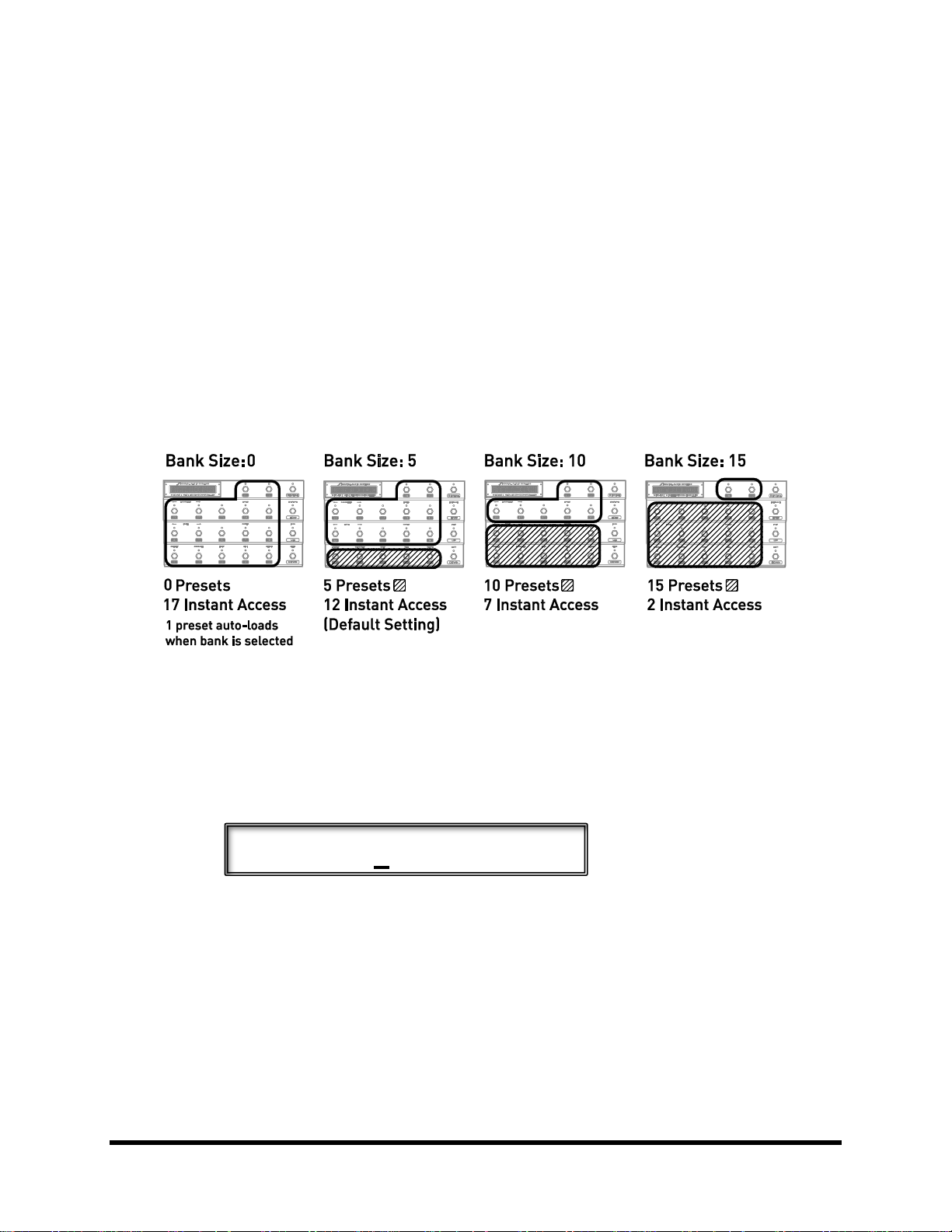
4.1 Bank Size
Bank Size determines how many footswitches will recall Presets and how many will control Instant Access
Switches (see Chapter 5). The MFC-101 defaults to a Bank Size of 5. This means that the first 5 footswitches load
Presets while 6-17 operate as Instant Access Switches. UP and DOWN step through Banks, each of which contains
the next 5 presets in numerical order (000-004, 005-009, etc.). Another way to see things is that Bank Size sets the
number of preset footswitches per bank—any number from 0 to 17.
Figure 4-1: Bank Sizes/Footswitch Layout Examples
To change the global Bank Size:
1. Press EDIT footswitch to enter EDIT MODE.
2. Press SETUP footswitch to select the SETUP menu.
Press PAGE 6x to get to the Bank Size Screen:
3. Press the UP and DOWN footswitches to set the desired value.
4. Press EXIT to return to PERFORMANCE MODE.
NOTES: Selecting 0 or 1 for bank size will cause one preset to load automatically as each bank is selected.
The total number of presets is not evenly divisible by all bank sizes, leaving unused spaces in the last bank. Pressing
a footswitch in the extra space at the end of the last bank will do nothing.
Bank Size is global, meaning it also governs the layout in SONG MODE and SET MODE (See SONGS & SETS on p. 35
for more on these modes and their features).
Doc v2.15 15

PRESETS & PRESET MODE Fractal Audio Systems MFC-101 Manual
4.2 Bank Style
Bank Style determines which preset will load automatically (or not…) when a new BANK or SONG is selected. The
default behavior is for the CURRENT preset footswitch to remain selected across bank changes. Other options
include loading the FIRST preset in the bank, or loading NOTHING until a preset footswitch is pressed. Note that
when the Bank Size is set to 0 or 1 the single preset per bank is always sent automatically. See section 12.5.7 on p.
61 for more information on changing the Bank Style.
4.3 Presets and Program Changes
As stated above, presets and banks in PRESET MODE are arranged in strict numerical order. The flexibility to have
footswitches load your choice of sounds, however, is offered in a number of ways:
By default, each numbered MFC-101 preset sends 16 Program Change commands—one on each MIDI
channel. These can be changed freely using the preset’s Program Change parameters. Preset numbers
0-999 may be specified. Bank select messages (CC#0) are automatic. See p. 42 for details.
In Axe-Fx Mode, the Preset Program Change for the MIDI channel of the Axe-Fx is determined by the
Axe-Fx Preset Transmit Map of the MFC-101. By default, this map is 1:1, but can be changed freely.
See p. 52 for details.
SONG MODE introduces a different type of flexibility. Songs are like banks, except you decide which
presets they contain, and in what order. An advantage of using Songs is that you can still switch back
to PRESET MODE at any time if you want the traditionally sequenced switching. See SONGS & SETS on
p. 35 for more details.
Finally, the Axe-Fx and many 3
functions. See documentation provided by the manufacturer.
NOTE: As described above, each MFC-101 preset can send MIDI commands which cause any Axe-Fx preset to be recalled, plus
up to 15 other MIDI Program Change messages for additional connected devices. Be aware of the distinction between “MFC-101
Presets” and “Presets” on your connected device(s). The MFC-101 always displays the number of its own preset, NOT that of the
current Axe-Fx preset or that of another device.
rd
party MIDI device(s) have their own internal Custom MIDI Map
4.4 Other Preset Capabilities
In addition to MIDI Program Change Commands described above, presets also have a number of additional
capabilities:
Presets store a snapshot of General Use IA Switch ON/OFF states. When the preset loads, the switch
states are set as stored and the corresponding burst of MIDI commands is set. Note: IA Switches with
Axe-Fx functions are NOT handled in this way. See Chapter 5 for more on IA Switches.
Presets store a snapshot of Internal CC states. Think of these of these as “virtual switches” which cause
a burst of MIDI commands when the preset is loaded. See Chapter 6 for more on Internal CCs.
Presets can be set up with a 16 byte custom MIDI message. See section 12.1.6.

Fractal Audio Systems MFC-101 Manual PRESETS & PRESET MODE
AlternatePreset GBL
Global External Switch settings can be overridden by any preset. See 12.1.7 on p. 45.
Global Expression Pedal settings and range can be overridden by any preset. See section 12.1.9 on p.
46.
Each preset also has an internal name, shown if AXE-FX MODE is OFF. See section 12.1.1 on p. 41.
4.5 Alternate Presets
Alternate Presets expand the number of sounds at your feet by allowing you to stack 2 presets per footswitch. This
allows you, for instance, to access your choice of clean and dirty sounds from one footswitch, or to have all 5
presets in a standard bank offer go to a “global” lead.
To load the Alternate preset, simply step on the footswitch of the selected preset a second time. Once the
Alternate Preset is loaded, its MIDI data is transmitted, the footswitch LED changes to red, and the preset number
in the display changes to GBL, ALT, or BAK to indicate the type of alternate preset you’ve landed on.
To set up an Alternate Preset for any given preset:
1. Load the preset you want to add an alternate to in the normal way (press its footswitch).
Note: You can also select any preset manually via the PRESET NUMBER screen shown between
steps 3 and 4, below.
2. Press EDIT footswitch to enter EDIT MODE.
3. Press PRESET footswitch to select the SETUP menu.
4. Press PAGE footswitch 3x to get to the Alternate Preset screen:
5. Press the INCR or DECR footswitch to make your selection:
GBL: The Global alternate preset will load (see below). This is the default.
0-383: The specified preset will be loaded as the alternate. (Bank select is automatic).
OFF: The Alternate preset will be disabled for this preset.
BAK: Loading the Alternate preset will dynamically “Backtrack” to whichever preset was
loaded before the current one.
6. Press EXIT to return to PERFORMANCE MODE.
Doc v2.15 17
 Loading...