

Fractal Audio AX8 Owner's Manual

AMP MODELER + MULTI FX
OWNER’S
MANUAL
Manual Version 1.00.2

Inside Front Cover

Declaration of Conformity
Manufacturer’s Name: Fractal Audio Systems, LLC
Manufacturer’s Address: 4 Wilder Drive, Plaistow, NH 03865 USA
Declares that the product:
Product name: AX-8 Product option: None
Conforms to the following Product Specications:
Safety: EN60065:2014
EMC: EN55013:2013
EN55020:2007+A11:2011
EN55024:2010
EN61000-3-2:2014
EN61000-3-3:2013
Supplementary Information:
The product herewith complies with the requirements of
the Low Voltage Directive 2006/95/EC
and the EMC Directive 2004/108/EC.
Cliord Chase
President / CEO
November 16, 2015
EMC/EMI
This equipment has been tested and found to comply with the limits for a Class B Digital device, pursuant to part 15 of the FCC rules. These limits are designed to provide reasonable protection against
harmful interference in residential installations. This equipment generates, uses and can radiate radio
frequency energy and, if not installed and used in accordance with the instructions, may cause harmful interference to radio communications. There is no guarantee that interference will not occur in a
particular installation. If this equipment does cause harmful interference to radio or television reception, which can be determined by turning the equipment o and on, the user is encouraged to try to
correct the interference by one or more of the following measures:
Reorient or relocate the receiving antenna.
Increase the separation between the equipment and receiver.
Connect the equipment to an outlet on a circuit dierent from that to which the receiver is con-
nected.
Consult the dealer or an experienced radio/TV technician for help.
i
Legal Notices
Fractal Audio Systems AX8 Owner’s Manual. Contents Copyright © 2015. All Rights Reserved.
No part of this publication may be reproduced in any form without the express written permission of
Fractal Audio Systems.
Fractal Audio, AX8, Humbuster, UltraRes, G3 Modeling Technology (“G3”), Multipoint Iterative Matching
and Impedance Correction (“MIMIC”), Virtual Vacuum Tube (“VVT”), Quantum Amp Modeling, are trademarks of Fractal Audio Systems. Manufacturer names and product names mentioned herein are trademarks or registered trademarks of their respective owners, which are in no way associated with or af-
liated with Fractal Audio. The names are used only to illustrate sonic and performance characteristics.
Important Safety Instructions
WARNING: To reduce the risk of re or electric shock, do not expose this
appliance to rain or moisture.
CAUTION: To reduce the risk of re or electric shock, do not remove screws.
There are no user serviceable parts inside. Refer servicing to qualied service
personnel.
1. Obey all warnings on the AX8 chassis and in this User Guide.
2. Keep away from sources of heat such as ducts, registers or appliances that produce heat.
3. Connect only to a standard grounded AC outlet of 100–240V, 47–63 Hz.
4. Keep the power cord in good condition. Do not kink, bend, or pinch.
5. If the cord becomes damaged, discard and replace it.
6. If not using your AX8 for extended periods of time, disconnect from AC power.
7. Protect the unit from rain and excessive moisture.
8. Refer servicing to qualied personnel only.
9. Stop operation of the unit and obtain service if:
- Liquids or excessive moisture enter the unit.
- The unit operates incorrectly or performance is inconsistent or erratic.
- The unit has been dropped and/or the enclosure damaged.
10. Prolonged exposure to high volume levels can cause hearing damage and/or loss. The
use of hearing protection in high volume situations is recommended.
ii

TABLE OF CONTENTS
1 INTRODUCTION ..................... 1
Welcome to the AX8 .....................1
Quick Overview .........................1
If you own an Axe-Fx... ...................2
If you Own an FX8... .....................3
Quick Connect Guide ....................4
Checking and Setting Levels .............5
Humbuster Cables .......................5
The Footswitches ........................6
The Footswitch page ....................7
The Grid Concept ........................8
2 HARDWARE OVERVIEW .............. 9
The Top Panel ...........................9
The Rear Panel ........................ 11
3 SETUP GUIDE .......................13
Full-Range/Direct Setup ............... 13
Setup: Power Amp & Guitar Speakers ... 14
Setup: Direct + Real Amp & Cabs ....... 15
Setup: FX Processor Only .............. 16
Checking and Setting Levels ........... 17
Connecting Pedals & Switches ......... 18
Connecting a Computer ............... 20
4 FUNCTION SWITCHES ...............21
F-Switches Overview .................. 21
Customizing F-Switches ............... 22
Sample F-Switch Layouts .............. 24
5 CREATING PRESETS ................. 25
What Is a Preset? ...................... 25
The Layout Grid ....................... 25
Working With Blocks ................... 26
Shunts ................................ 27
Connector Cables ..................... 27
Moving Blocks. . . . . . . . . . . . . . . . . . . . . . . . . 28
Block Inventory ....................... 29
Example Preset Grids .................. 30
Editing Eect Blocks ................... 31
Saving Changes ....................... 32
Setting Up Footswitches 1-8 ........... 33
X/Y Switching ......................... 34
Preset CPU Limits ...................... 35
AX8-Edit .............................. 36
6 SCENES ............................ 37
Overview ............................. 37
Selecting Scenes ...................... 38
Setting Up Scenes ..................... 38
Scene Revert .......................... 40
7 BLOCKS GUIDE ..................... 41
The Amp Block ........................ 42
The Cab Block ......................... 51
The Looper Block ...................... 54
The FX Loop ........................... 57
The Noise Gate ........................ 60
The Output Mixer ..................... 61
Mix Page Common Parameters ........ 62
8 MODIFIERS ......................... 63
Overview ............................. 63
Creating a Modier .................... 63
Modier Example: Wah Pedal .......... 64
Modier Sources Overview ............ 65
Modier Tips And Tricks. . . . . . . . . . . . . . . . 65
Advanced Modier Parameters ........ 66
Internal Controllers .................... 69
External Controllers ................... 70
9 TEMPO ............................. 71
Preset Tempo .......................... 72
Auto Delay ............................ 72
The Metronome ....................... 72
10 THE TUNER ........................ 73
Advanced Tuner Functions ............. 73
11 SETUP MENUS ....................75
The Global Menu ...................... 75
The I/O Menu ......................... 78
The Utility Menu ...................... 83
12 ADDITIONAL TOPICS .............. 85
Global Volume Pedal Setup ............ 85
Spillover .............................. 86
Up- vs. Down-Stroke Fx Switching. . . . . . 87
Frequently Asked Questions ........... 88
Transferring Blocks Between Products .. 91
Main Menu Soft Knobs Guide .......... 92
Hidden Edit Button Functions .......... 92
13 SPECIFICATIONS & DEFAULTS ...... 93
MIDI Implementation .................. 94
Factory Default MIDI CC Settings ....... 95
MIDI Program Change Numbers ....... 96
WARRANTY ..........................99
EULA ...............................100
iii

THANK YOU FOR CHOOSING THE AX8
Thank you for choosing the AX8, an all-in-one guitar processor designed for the stage and studio featuring
Fractal Audio Systems’ legendary amp modeling and eects processing.
Since the original Axe-Fx turned the modeling world upside-down, users have clamored for a form-factor
with reduced footprint and weight. The AX8 brings the vaunted sound of the Axe-Fx II to a convenient oor
package that enhances portability and usability without sacricing all-important tone. It’s perfect for “y
dates” and “corporate gigs” where space is constrained, yet equally suitable for professional performances
and studio sessions.
The AX8 was purpose-designed for the rigors of the road and features a sturdy steel chassis with aircraft
aluminum side panels. An integrated power supply eliminates the clumsy and failure-prone “wall wart”
commonly used in other products. Our exclusive, proprietary “Silent Switching Technology” uses no
mechanical contacts so there are no switches to fail in the heat of battle. As with all Fractal Audio products
only the best components are used in the critical signal path, featuring audiophile-grade converters and
linear components.
If you are an experienced Axe-Fx user you will be right at home with the AX8. We’ve packed all our revolutionary
technologies into this little box: Quantum amp modeling, UltraRes™ cabinet technology, Humbuster™ I/O,
and more, along with our renowned eects and usability features.
As with all our products, rmware updates and a software editor are oered free-of-charge. Our Fractal-Bot
utility is also compatible with the AX8 to facilitate rmware updates and backups of your precious presets.
Most importantly, the AX8 continues our tradition of “no corners cut”. Our unique company structure along
with our direct sales model means higher quality at a lower price. We don’t answer to share-holders and
corporate bean-counters so we don’t cut corners on the quality of the components going into our products.
This, along with our obsession with “being the best” leads to stellar reliability, performance and, most
importantly, that “legendary Fractal Audio sound”.
So grab your guitar and get ready for a journey into tone-land...
Fractal Audio Systems
November 2015
iv

1 INTRODUCTION
1 INTRODUCTION
WELCOME TO THE AX8
The AX8 is an advanced amp modeler and multi-eects pedalboard processor, perfect for guitar, bass,
and other instruments. The unit is “built like a tank” with a steel chassis and aircraft aluminum end panels,
featuring eleven quiet, durable, solid-state footswitches with no mechanical contacts to fail, 27 LEDs in
three colors, a brilliant LCD display, six buttons including SHIFT for extra functions, ve soft knobs, and eight
dedicated LED-indicator knobs for essential amp functions. It has an instrument input, XLR, Humbuster
and S/PDIF main outputs, a stereo eects loop (which also doubles as a auxilliary input/output for special
applications) and four jacks for external switches or expression pedals.
Like every Fractal Audio Systems product, the AX8 puts sound quality rst. It uses high quality D/A and A/D
converters for a pristine signal path and ultra-low noise levels. The on-board dual processors run the same
high-quality eect algorithms made famous in the Axe-Fx II.
We hope you nd the unit easy to use and this manual easy to read. The most important sections are
those which introduce the basics of how the unit works. If nothing else, be sure to review this section, plus
“Hardware Overview” and “Setup Guide” on p. 13.
QUICK OVERVIEW
The AX8 contains 512 dierent presets
arranged in 64 numbered banks.
Each preset is like an entire rig, with its
own amp, speaker cab, and eects.
The AX8 features over 222 “Quantum”
amp models utilizing the same
technology as our agship Axe-Fx II.
Ultra-Res™ Speaker Cab simulation provides
a level of accuracy that only Fractal Audio
Systems can oer. AX8 is also compatible
with our entire library of Cab-Packs.
Presets are extremely exible with the
familiar “Layout Grid” from the Axe-Fx II.
Most blocks oer X/Y switching for twice as
many sounds from the same number of blocks.
Each preset contains eight scenes. Think
of a Scene as a preset within a preset.
Scenes eliminate “tap dancing” by turning
multiple eects on or o with a single
tap, switching X/Y states, and more.
Every preset can have its own custom
footswitch 1-8 assignments.
There are over 16 dierent useful
“Footswitch Blocks” such as “Scene 1/2
Toggle” or “Looper Control Mode”.
Footswitches can also be designated as
“GLOBAL”, which gives them the same
assignment across ALL presets in the AX8.
3 assignable Function Footswitches oer over
a dozen options so you can create the perfect
layout of “modes” for your musical performances.
On-board jacks for four external footswitches
or expression pedals make it easy to
remote-control sound functions.
MIDI and USB also provide powerful
options for control, editing, and more.
AX8-Edit, a free software editor, makes
it possible to edit presets, eects, and
more when connected to a Mac or PC.
And much more! Please take the time to
familiarize yourself with this manual.
Should you need any assistance with the AX8,
please visit http://www.fractalaudio.com
1

1 INTRODUCTION
IF YOU OWN AN AXE-FX...
The AX8 is a dream come true for many Axe-Fx owners. Whether it is your backup rig or your new main
unit, we hope you will be pleased with what many are already calling the “Axe-Fx Junior on the Floor.” This
convenient grab-and-go unit contains the very best features of the Axe-FxII, including the latest Quantum
Amp models, Ultra-Res™ Cabs, loads of eects, the 4x12 grid, and more.
Here are some quick tips that you as an Axe-Fx owner may nd helpful as you get to know the AX8.
1. ALL of the amps are here! ALL of the factory cabs are here! All of your existing Axe-Fx II Cab-Packs and
user cab les are 100% compatible. All of the eects are basically the same as their counterparts in the
Axe-Fx, but the inventory is dierent. Review “Block Inventory” on p. 29
2. The AX8 has an impressive amount of CPU power—but not as much as the agship Axe-Fx II. In
comparison to the Axe-Fx, it also disables blocks automatically if CPU usage gets too high.
See “Preset CPU Limits” on p. 35 to learn more.
3. Instead of a RECALL screen, the AX8 boots to the Footswitch Page—the rst page of its main menu.
Think of this like the MFC-101 (our MIDI foot controller): as you edit it, the Footswitch Page doesn’t ever
change what you hear, just what the footswitches do.
Review “Setting Up Footswitches 1-8” on p. 33 and “Function Switches” on p. 21
4. Instead of a LAYOUT button, the Grid is accessed as the second page of the main menu.
Press PAGE> from the Footswitch Page to access it. Press EXIT to return to the Footswitch Page.
5. Instead of four NAV buttons, you will primarily use the E/NAV knob to get around menu pages.
One noteworthy exception is that when you want to assign a modier to a knob, you will need to select
it using the NAV left and right buttons accessed as SHIFT + ENTER and SHIFT + EXIT.
6. There is no main “VALUE” knob; instead you’ll use A,B,C,D, and E knobs as indicated in the display.
DON’T FORGET about the eight dedicated LED-ring amp controls!
7. Instead of dedicated X and Y buttons, you’ll typically press and hold a footswitch to toggle X/Y for an
eect, or if no footswitch is assigned, select or edit the eect and double-tap EDIT.
8. When used to create an Auxilliary Output, the FX Loop Block must be placed in parallel rather than
series. (Unlike the Axe-Fx, the AX8 does not detect when a plug has been inserted into INPUT 2.)
9. In comparison to the MFC-101, BYPASS/ENGAGE footswitches execute on the switch up-stroke instead
of the down-stroke. Learn more, (including how to change this if you wish) in
“Up- vs. Down-Stroke Fx Switching” on p. 87.
10. AX8-Edit is so similar to Axe-Edit that using it overcomes the above front panel dierences with ease.
11. The Axe-Fx II and AX8 cannot share presets, but you CAN transfer individual block settings from one
product to another using our editor software applications, Axe-Edit and AX8-Edit.
See ”Transferring Blocks Between Products” on p. 91.
12. The AX8 has FOUR jacks for external switches or pedals, not one or two.
13. All of the 1/4” outputs use Humbuster™ Technology, compatible with all existing Humbuster cables.
14. Fractal-Bot is fully supported. Use it for rmware updates, backup/restore operations, and more.
2

1 INTRODUCTION
IF YOU OWN AN FX8...
The AX8 looks very similar to the FX8, but there are some important dierences. The FX8 is intended for use
with a tube amp, while the AX8 is primarily intended for going “direct.” Later you’ll learn how it can also be
used with real amps and guitar speakers, but at rst you’ll surely want to connect the unit to some studio
monitors, full-range guitar speakers, or a high-quality PA system.
Here are some quick tips that you as an FX8 owner may nd helpful as you get to know the AX8.
1. Instead of STOMPBOX MODE, the AX8 boots to the Footswitch Page—the rst page of its main
menu. The Footswitch page is very dierent from Stompbox Mode in that it only changes footswitch
assignments. It does NOT determine which eects are in the preset, or what order they are in. Think
of the Footswitch Page almost like a separate foot controller. The three right F-Switches are also fully
programmable, allowing you to decide what you want each one to do by choosing from a menu.
Review “Setting Up Footswitches 1-8” on p. 33 and “Function Switches” on p. 21
2. Again, the Footswitch Page has no eect on what you hear. Instead, eect blocks are placed and must
be connected using the Layout Grid on the second page of the main menu. To display the grid,
press PAGE> from the Footswitch Page. Press EXIT to return to the footswitch screen.
Review “The Layout Grid” on p. 25
3. The AX8 uses a exible architecture that does NOT designate separate “Pre” and “Post” chains.
It is still possible to use a four-cable method hookup, but this needs to be set up manually in each
preset using the FX Loop block (p. 57) to insert your preamp.
4. In add ition to using Press-and-Hold footswitches to toggle X/Y, you can also select or edit an eect
and double-tap EDIT. (This is good to know because some blocks may not have footswitches assigned.)
5. Unlike the FX8, the AX8 is NOT specically designed for unity gain, but when you’re using it “direct” this
really should not be a concern.
6. The eects of the AX8 are mostly the same as those in the current FX8 rmware, but there are a few
changes. Review “Block Inventory” on p. 29
7. There are no RELAYS. Instead, the AX8 has four jacks for external switches or pedals.
8. The AX8 Looper is not “global,” meaning it needs to be inserted as a block on the grid for every preset
where you want to use the Looper. Review “The Looper Block” on p. 54
9. Once you understand the Grid, AX8-Edit is remarkably similar to FX8-Edit.
10. The FX8 and AX8 cannot share presets, but you CAN transfer individual block settings from one product
to another using our editor software applications, FX8-Edit and AX8-Edit.
See ”Transferring Blocks Between Products” on p. 91.
11. All of the 1/4” outputs use Humbuster™ Technology. All existing Humbuster™ cables are compatible.
12. Fractal-Bot is fully supported. Use it for rmware updates, backup/restore operations, and more.
3
1 INTRODUCTION
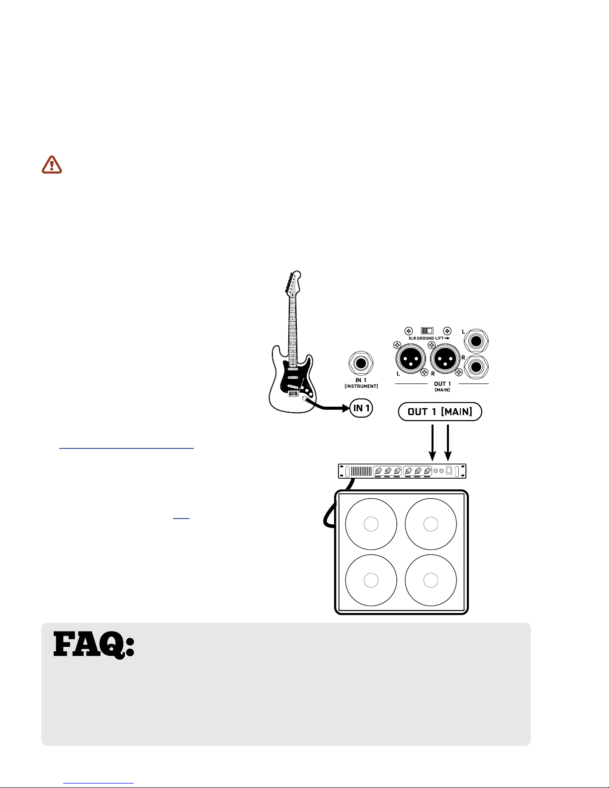
QUICK CONNECT GUIDE
The best and most exible way to enjoy your AX8 is through a full range system. In comparison to
traditional guitar speakers, the extended range of such a system is able to reproduce the very broad
spectrum of frequencies produced by all of the dierent amp models, speaker sims, and eects. Think
of it this way: a 1x12” open-back guitar speaker is never going to sound like a 4x12 stack, but full range
monitors or PA speakers are designed to reproduce the sound of anything you throw at them—right
down to an entire band.
If you do NOT plan on “going direct” with a full range system, please see “Setup Guide” on p. 13 for
instructions about how to use the AX8 in other congurations (but do also make a point of looking into
the many options available for full range guitar systems).
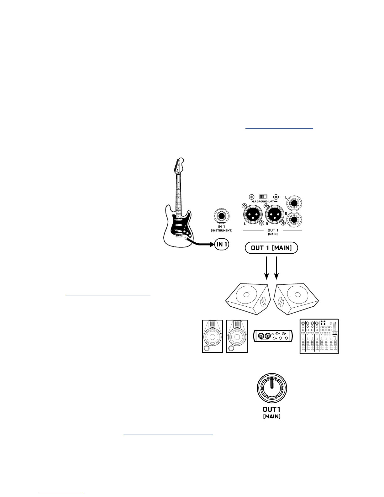
Begin with all level knobs turned down.
q
Connect your guitar to IN1 [INSTRUMENT].
The AX8 is also perfect for bass
and other instruments.
Connect OUT 1 [MAIN] to a mixer,
w
studio monitors, audio interface, PA system,
full-range speakers, amp inputs, etc.
• For a mono rig, use the LEFT output only.
• Use XLR Outs to feed balanced Inputs.
You can nd high quality XLR and other
cables at http://btpa.com/fractal-audio
• Use the 1/4" Outs when connecting
to unbalanced Inputs.
• Use Humbuster™ cables with
1/4” outs to reduce hum from
ground loops. (See next page.)
Turn up the OUT 1 [MAIN] LEVEL knob
e
and adjust the level on your monitors as desired.
Out 2 is not used in this setup.
Find additional setup diagrams in Section 3: Setup Guide on p. 13.
4
1 INTRODUCTION
CHECKING AND SETTING LEVELS
Setting proper levels is critical. Two meters (one mono and one stereo) plus two
front panel LEDs inform you about levels on the AX8. Setting levels is easy.
INPUT 1 [INSTRUMENT] LEVELS
The AX8 comes ready-to-use for the typical guitar with passive pickups. Connect a
guitar to INPUT1. Choose your loudest pickup setting and set all the guitar controls
to “wide open.” Play loud, open chords to push the levels as you watch the IN 1
[INSTRUMENT] meter LEDs. It’s OK to tickle the red LED once in a while, but if you
push too hard, the input will clip and you’ll need to pad the input as follows:
Press SETUP followed by footswitch 2 for the “I/O” menu. It should open to the “LEVELS“ page.
Turn E/NAV to select INSTRUMENT INPUT PAD. Turn the “A” knob to Increase this setting beyond
6dB, 12dB or 18dB. Be aware that as you increase this PAD setting you also increase the noise oor,
so set it as low as possible. Conversely, if you can set this to 0dB for a guitar with quiet output,
you’ll get even better signal-to-noise performance.
OUT 1 LEVELS
OUT 1 [MAIN] XLR and 1/4" Humbuster™ jacks are ready to be connected to professional line-level
+4dBu inputs. If you are connecting to consumer-grade equipment operating at -10 dbV, please set
the nominal output level as follows:
Press SETUP; Press footswitch 2 for the I/O menu; Turn to the LEVELS page.
Turn E/NAV to select MAIN OUT NOMINAL LEVEL and change this setting to “-10 dBV”.
FRONT PANEL “CLIP” LEDS
If the MAIN OUT CLIP or FX SEND CLIP LEDs light, see “Checking and Setting Levels” on p. 17
for more information about the various controls and settings used to solve clipping problems.
HUMBUSTER CABLES
Standard 1/4” guitar cables are ne for all audio connections to and from the AX8, but there is a better
option for connecting its outputs to your amp, modeler or other device. Humbuster™ technology on all
AX8 outputs can signicantly reduce unwanted noise due to the common problem of a ground loop. For
this to work, you need to use a special Humbuster™ cable you can buy or make yourself.
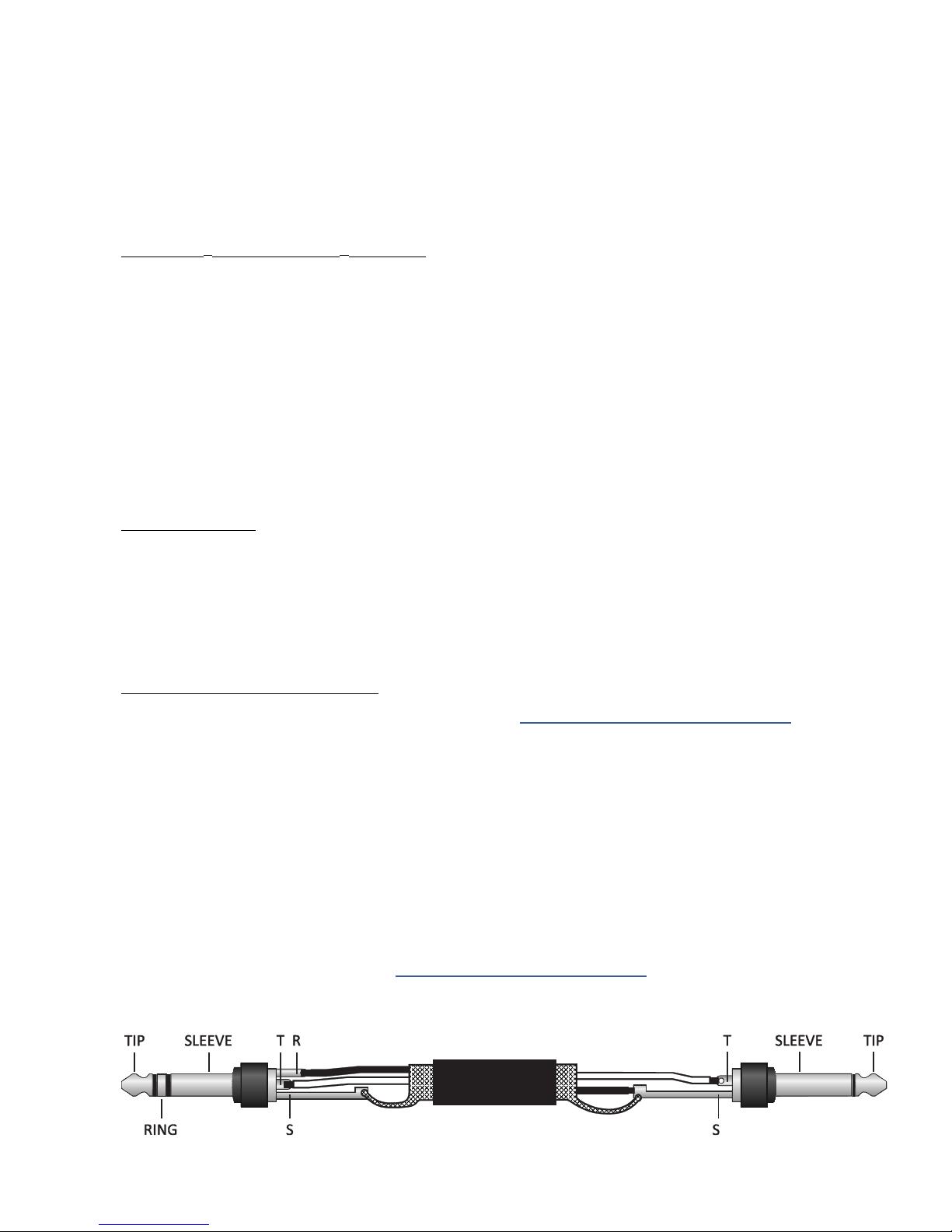
A Humbuster™ cable has one TRS end (like a balanced cable) and one TS end (like a guitar cable). The TRS
end connects to the AX8. The TS end connects to your amp.
Humbuster™ cables are available from http:/www.fractalaudio.com/cables or you can make your own by
following the diagram below. Be sure to use high-quality connectors and shielded cable.
5
1 INTRODUCTION
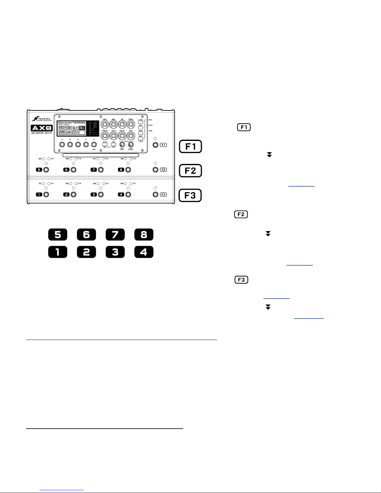
THE FOOTSWITCHES
Once you have set up your AX8 with speakers/amps/monitors, you can begin to audition the factory preset
sounds. The AX8 has eleven footswitches divided into two groups: “F-Switches” and numbered footswitches.
Their default functions—detailed here—are perfect for how most players will use the AX8.
THE F-SWITCHES
Tap for Preset Select Mode
F2 and F3 work as Bank Up/Down.
Select a preset with footswitches 1–8.
Press and hold F1 to enter “Sticky”
Preset Mode which remains active until
you tap F1 again to exit.
Learn about Presets in Section 5.
FOOTSWITCHES 1-8
Footswitches 1–8 perform the functions shown
in the display (see next page). They are also used
for other functions in modes activated by the
F-Switches (like selecting Presets or Scenes).
Tap for Scene Select Mode then
Select a Scene with footswitches 1–8.
Press and hold F2 to enter “Sticky”
Scene Mode which remains active until
you tap F2 again to exit.
Learn about Scenes in Section 6
Tap to set the Tempo. Some eects
use times or rates controlled by Tempo.
Learn more in Section 9
Press and hold F3 to display the Tuner.
Learn about the Tuner in Section 10
TO CHANGE PRESETS WITH THE FOOTSWITCHES...
The AX8 has 512 Presets, each a complete rig containing Amp, Cab, eects, and more.
When you power it on, the unit loads whichever (non-empty) preset was loaded when you powered it o.
To change presets:
Tap the F1 Switch to enter Preset Select Mode.
Press F2 for BANK UP or F3 for BANK DOWN.
Select from switches 1–8 to load a preset within the bank shown, or press F1 to cancel.
TO CHANGE PRESETS WITH THE KNOBS...
On the main Footswitch Page, you can also fast-scroll through presets or scenes:
The “B” knob fast-scrolls through PRESETS.
The “C” knob fast-scrolls through SCENES. (Say it to remember it: “C... Scenes.”)
6
1 INTRODUCTION
THE FOOTSWITCH PAGE
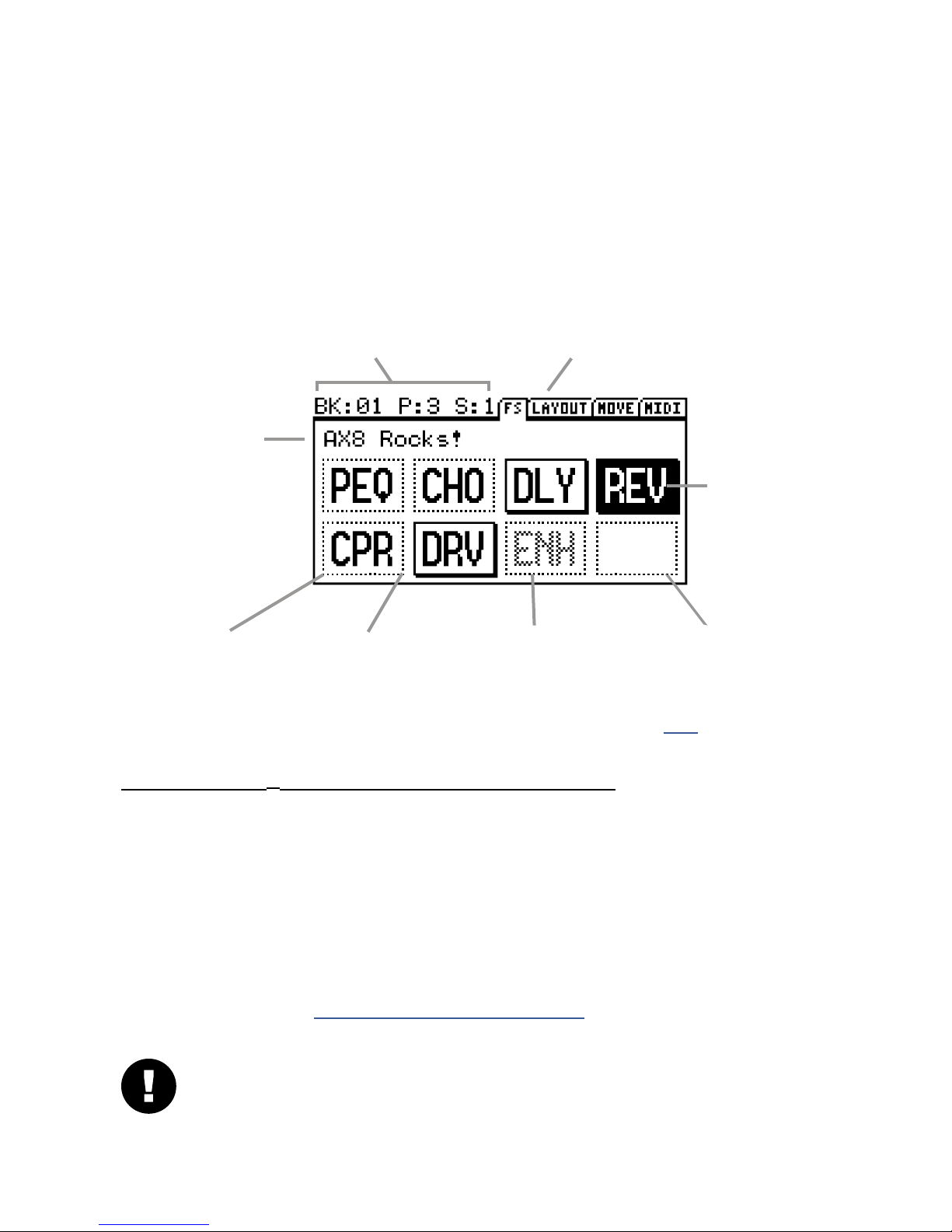
When you power on the AX8, it defaults to the Footswitch Page of the main menu (as indicated by “FS” in the
menu tab). The current functions of footswitches 1-8 are displayed here. The diagram below provides a basic
understanding of what you’re seeing on the Footswitch Page.
The upper left area shows the
current BANK, PRESET and SCENE.
The NAME of the
current preset
A DOTTED outline
indicates that this
switch is OFF.
A >BLINKING< footswitch indicates an eect disabled for CPU reasons. See p. 35 for more on this.
A SOLID outline
indicates that this
switch is ON.
A GRAYED footswitch indicates
an eect not found in the
current preset.
The upper right shows the
pages of the main menu.
The SELECTED switch
is shown in inverse.
An EMPTY space
indicates a footswitch
with nothing assigned.
FOOTSWITCH 1–8 ASSIGNMENT QUICKSTART GUIDE
Footswitches 1–8 can be assigned to any eect in the current preset. To change a footswitch in a preset:
Select the footswitch you want to change. (Stomp it or turn the E/NAV knob to select it in the display.)
Turn the A knob to cycle through the list of blocks.
When you nd what you’re looking for, press ENTER to conrm, or press EXIT to cancel.
Save your changes by pressing STORE, ENTER, ENTER.
You will also notice various “Footswitch Blocks” in the list of blocks. These perform a variety of functions like
selecting presets in the current bank, changing scenes in the current preset, displaying the Looper, and more.
Learn more about this in in “Setting Up Footswitches 1-8” on p. 33
IMPORTANT! Footswitch assignments do not change which eects are (or are NOT) in your preset.
If you think of the AX8 as a separate guitar processor and foot controller, this would be the foot
controller portion. The Layout Grid (see next page) determines which eects are in the signal path.
7
1 INTRODUCTION
THE GRID CONCEPT
Behind the scenes of every AX8 preset is the Layout grid. Learn it. Love it. Live it. Here’s the concept.
In the world of traditional gear, most of us have very limited options, and building a rig requires making
hard choices and commitments. With the AX8, these limitations are removed and you have a vast, evergrowing “inventory” of virtual amps, cabs, eects, and more. Virtual gear is selected from the inventory and
placed as “blocks” into the slots of a 12×4 “layout grid.” As you might expect, blocks must be wired up using
cable-like “connectors”—again, virtual ones in this case—and you can create splits or merges as needed.
Passive “shunts” are be used to carry signal through otherwise empty spaces on the grid.
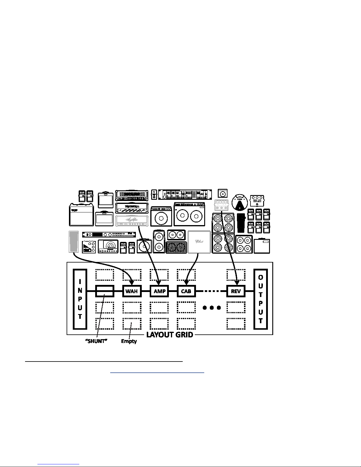
The following illustration shows various pieces of gear from an inventory, all interconnected on the grid.
Signal ow begins at the INPUT on the left. Signal is routed through a SHUNT to feed a Wah block. The
shunt has no eect on the sound and is shown only to introduce the concept of its use. The Wah block is
connected to an Amp block (we might set its type to “Plexi 100W High”), which in turn feeds a Cab—one
of the many “4x12” options, perhaps. This is connected to a reverb (“REV”) and then to the OUTPUT. Many
grid spaces are empty. The size of a preset is limited only by the grid structure, block inventory, and total
processing power or “CPU”. The AX8 has enough CPU power to create countless incredible virtual rigs.
GRID AND BLOCK EDITS QUICKSTART GUIDE
You’ll learn all about the grid in Section 5: Creating Presets on p. 25, but here’s a quick primer:
From the main Footswitch page, press PAGE RIGHT to show the grid (“Layout” tab).
Turn the D or E knobs to navigate the grid.
Turn the A knob to cycle through blocks at the current grid location.
Press ENTER to insert or change the eect. Press EDIT to access its parameters.
Use all ve knobs to edit on-screen parameters. Use E/NAV to navigate menu pages.
To save changes, press STORE, ENTER, ENTER.
Press EXIT to switch from the Layout Grid to the Footswitch Page.
8
2 HARDWARE OVERVIEW
2 HARDWARE OVERVIEW
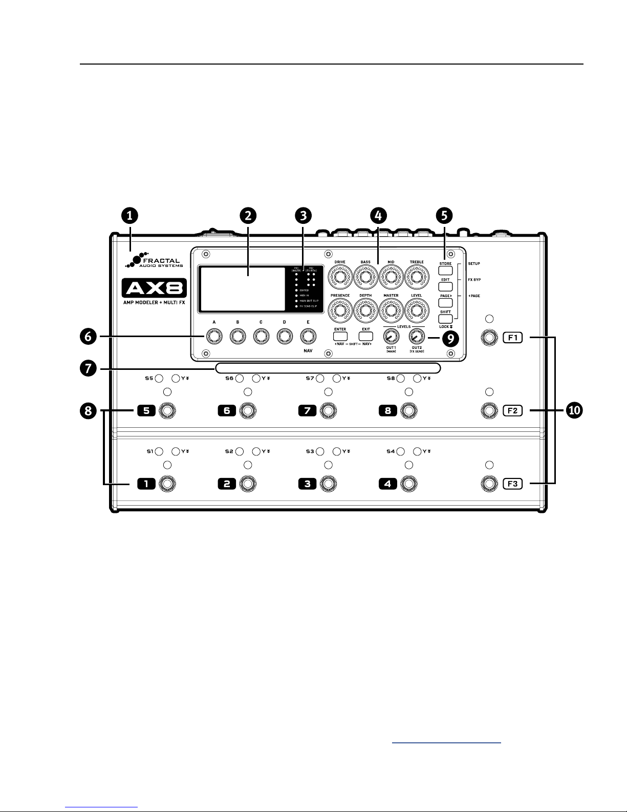
THE TOP PANEL
The AX8 is housed in a powder-coated steel chassis with an aircraft aluminum bezel and end-caps.
q
The 160 × 80 pixel LCD is where all menu screens are displayed.
w
METER and STATUS LEDs communicate important information:
e
IN 1 [INSTR] and IN 2 [FX RTN] meters show input levels. Signal can “tickle the red” before clipping.
EDITED – This LED is lit when the current preset has been altered but not stored.
MIDI IN – This LED is lit while MIDI messages are being received at the MIDI IN port.
MAIN OUT CLIP – This LED is lit when signal overloads OUT 1 (MAIN) and causes clipping.
FX SEND CLIP – This LED is lit when signal overloads OUT 2 (FX SEND) and causes clipping.
Eight AMP CONTROL KNOBS adjust DRIVE, BASS, MID, TREBLE, PRESENCE, DEPTH, MASTER and LEVEL
for the current preset. LED rings show values as they change, updating automatically when you select a
new amp TYPE, change presets, or toggle between X and Y (see “X/Y Switching” on p. 34).
9
2 HARDWARE OVERVIEW
Six Buttons provide access to the various functions and menus of the AX8.
STORE – Stores the current preset to memory so it can be recalled in the future.
EDIT – Opens the Edit Menu for the currently selected eect block.
PAGE – Steps to the right through menu pages, shown as “tabs.”
ENTER – Executes commands, commits changes, accesses sub-menus, and more.
EXIT – Works as cancel, escape, and more.
SHIFT – The SHIFT key gives every button a second function. Press and hold for SHIFT LOCK.
SETUP (Shift+Store) – opens the SETUP menus (which you select from using footswitches).
FX BYP (Shift+Edit) – bypasses the selected eect without using a footswitch.
3PAGE (Shift+Page>) – steps to the left through menu pages, shown as “tabs.”
3NAV (Shift+Enter) – moves the onscreen cursor or focus to the left.
NAV (Shift+Exit) – moves the onscreen cursor or focus to the right.
A,B,C,D, and E SOFT KNOBS (aka “Multifunction Endless Rotary Encoders” for you slide-rule types...)
perform dierent functions depending on which screen is shown in the display. Most screens show ve
(or fewer) knobs for easy 1:1 operation. Knob E is also used for NAV, which navigates on-screen menus.
The HANDLE also serves as a GUARD to protect the knobs of the AX8 from being kicked and broken.
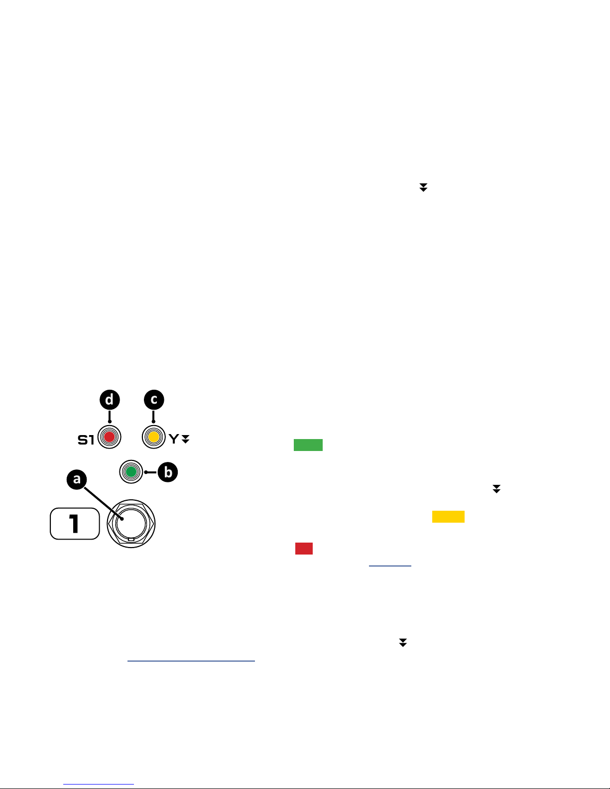
There are eight main FOOTSWITCHES corresponding to the eight eect slots. Each has three LEDs.
a. FOOTSWITCH – Step on it! Footswitches are used to toggle eects, select
scenes, etc. The AX8 utilizes our fast, quiet Solid State Switches (SSS™) with
no mechanical contacts to break or fail.
b. BYPASS LED – The green LED above the footswitch shows whether the
eect assigned to this footswitch is ON or OFF.
c. Y LED – Many eects on the AX8 oer X/Y switching for two dierent
sound settings from a single block. By default you press and hold the
footswitch to toggle the X/Y state of the corresponding eect, though
certain settings change the way you toggle X/Y. The amber LED indicates
that an eect has been switched to its Y setting.
d. SCENE LED – Eight red LEDs labeled S1, S2, etc. indicate which Scene is
loaded within the current preset. (See Section 6 for more on Scenes.)
Two OUTPUT LEVEL CONTROL KNOBS adjust the levels at the MAIN OUT (12) and FX SEND (13) jacks.
The three FUNCTION FOOTSWITCHES, also known as “F-Switches” are used to change modes and
a
access various features of the AX8. Each of them has a primary function activated when you tap the
footswitch, and a secondary function activated when you Press and hold it.
Learn more in Section 4 Function Switches.
10
2 HARDWARE OVERVIEW
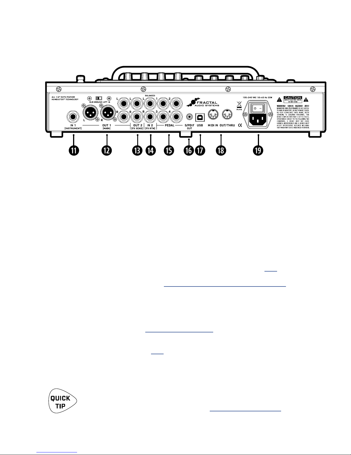
THE REAR PANEL
IN 1 [INSTRUMENT] – (Mono, unbalanced 1/4" Jack)
Connect your guitar, bass, or any instrument-level source here using a regular guitar cable.
You can also connect the output of other guitar pedals or eects.
OUT 1 [MAIN] L+R – (Two XLR-M and Two 1/4" Humbuster™ Jacks)
The main output of the AX8 appears at these jacks. Use the XLR jacks to connect to a mixer, studio
monitors, PA, or other device with balanced inputs. Use the ground lift switch if necessary to reduce
hum from ground loops. Use the 1/4" unbalanced Humbuster™ jacks to connect to unbalanced inputs
such as those on power amps. Both the XLR and the 1/4" jacks always output exactly the same signal
and may be used simultaneously. The OUT 1 MAIN level knob (9) controls both at the same time.
OUT 2 [FX SEND] L+R – (Two 1/4" Humbuster™ Jacks)
Connect to the input(s) of outboard equipment when using the FX Loop block (p. 57). This
block can also be used to turn OUT 2 into a utility output so you can send signal with and without
cabinet simulation at the same time. See “Setup: Power Amp & Guitar Speakers” on p. 14 for more
information on this type of setup.
If the FX Block is not used, a special system parameter called OUT 2 (FX SEND) ECHO can be used to
specify the source for OUT 2. Applications include recording raw, dry, direct guitar for re-amping or
using the OUT 1 and OUT 2 level knobs for separate Front of House and onstage FRFR levels.
See OUT 2 FX SEND ECHO under “I/O: Audio Page” on p. 79.
IN 2 [FX RTN] L+R – (Two Balanced 1/4" Tip-Ring-Sleeve Jacks)
g
These jacks feed the FX Loop block (p. 57), wherever it is placed in your presets. Aside from the
obvious use of inserting outboard equipment, the FX Loop block can also be used to turn IN 2 into
a utility input to feed a given preset a second input signal such as that from the piezo output of a
dual-output guitar.
Humbuster™ Technology on all OUT 1 [MAIN] and OUT 2 [FX SEND] 1/4" jacks can
signicantly reduce hum from ground loops when used with special Humbuster Cables
available at http://shop.fractalaudio.com. See also “Humbuster Cables” on p. 5.
11

2 HARDWARE OVERVIEW
PEDAL 1–4 – (1/4” Tip-Ring-Sleeve Jacks)
h
These jacks are used to connect up to four external expression pedals or switches to control various
functions of the AX8. Use the PEDAL page in the I/O menu under SETUP to calibrate each connected
pedal, and the CTRL page of the I/O menu under SETUP to assign pedals to various functions or
modier sources. For more on using these jacks, see “Connecting Pedals & Switches” on p. 18.
S/PDIF OUT – This outputs a digital copy of the Main Output. The S/PDIF clock is xed at 48kHz.
j
USB – This provides the AX8 with two-way “MIDI-over-USB” capabilities when connected to a
k
compatible Mac or PC. No driver is required. The AX8 does not have USB audio capabilities.
The MIDI IN port of the AX8 allows you to control various MIDI functions including preset and Scene
l
selection, eect bypass, X/Y changes, parameter changes, and more.
The MIDI page of the I/O menu under SETUP is used to congure MIDI Channel and other options.
See “I/O: Midi Page” on p. 80.
The MIDI OUT jack transmits MIDI data to connected devices.
MIDI data can be programmed to be sent automatically when you select a Scene.
To learn about Scenes, see Section 6.
Main Power Input and switch – Insert the supplied power cable and connect the other end to a
;
grounded AC power receptacle. The AX8 has a universal power supply, which means it can be used
around the world by simply changing the cable. The main power switch is built in to the receptacle. We
recommend switching the AX8 o when it will not be in use for an extended period of time.
12

3 SETUP GUIDE
3 SETUP GUIDE
FULL-RANGE/DIRECT SETUP
The “Quick Connect Guide” on p. 4 covers using the AX8 “direct” with full-range studio monitors, FRFR
Guitar Speakers, or a PA System.
This type of setup takes full advantage of the ability of the AX8 to simulate not only dierent amps,
but power amps, speakers, microphones, and extended-frequency-range eects as well. It is the most
versatile and popular setup.
The pages which follow are provided for those who want to use the AX8 in a dierent type of setup.
13
3 SETUP GUIDE
SETUP: POWER AMP & GUITAR SPEAKERS
A full-range system is the most exible and versatile, but it is not for everyone. Another great way to use the
AX8 is through a power amp connected to traditional guitar speakers.
IMPORTANT: For this setup, please disable CAB MODELING under GLOBAL SETTINGS.
• Open the GLOBAL menu (press SETUP followed by Footswitch 1) and nd the SETTINGS page.
• NAV to CABINET MODELING and then use VALUE to select “OFF”.
• Depending on your amp, you may also wish to set POWER AMP MODELING to “OFF”. Let your ears
decide.
• Press EXIT twice to return to the Footswitch Page.
NOTE: Instead of disabling cab modeling, you could also bypass or remove the CAB block in every preset.
Begin with all level knobs turned down.
q
Connect your guitar to IN1 [INSTRUMENT].
Connect your power amp to your
w
speakers. Connect OUT 1 [MAIN]
to the input of your power amp.
• Use the XLR Outs if your amp has
balanced Inputs. You can nd high
quality XLR and other cables at
http://btpa.com/fractal-audio
• Use the 1/4" Outs when connecting
to unbalanced Inputs.
• For a mono rig, use the LEFT output only.
• Use Humbuster™ cables (p. 5) with
1/4" outs to reduce the hum from
ground loops.
• Adjust levels by turning up the Out1
Level knob and your amp.
SPKR
OUT
SPKR
IN
POWER
AMP
GUITAR
SPEAKER
CABINET
WHAT KIND OF POWER AMP? There are two categories to consider.
A sonically neutral or “at” power amp designed for a PA or made specially for full-range
guitar is generally considered the best choice. These amps (almost always solid-state) allow the power amp
simulation in the AX8 to vary the tone and dynamics appropriately as you select from dierent virtual amp
types. The second category contains tube amps specically made for guitar. This type can also be used, but
you’ll be “stuck” with one “avor” of power amp all the time— one tonal color, one feel, though this can be
great if its what’s you like. There are no wrong answers in any case. Use your ears!
14

SETUP: DIRECT + REAL AMP & CABS
In this setup, custom presets simultaneously send two
dierent signals—one WITH and one WITHOUT speaker
sims—to front-of-house and backline.
The MAIN outs connect to a full-range system—typically
the house PA—sending a complete virtual rig tone,
including simulated speakers. This provides all the
benets of going direct: versatile, consistent tone without
“bleed” at very controllable volume levels for a better
overall mix. (Ask a live mix engineer how much they love a
really loud guitar amp on stage. I dare you.)
OUT 2 sends a separate signal, almost identical to the rst,
but without speaker sims. This connects to a power amp
and real guitar speakers on stage for a familiar “backline”
experience that players enjoy, enhancing natural sustain,
“moving air,” lling the soundspace in a traditional way,
and even providing “front ll” for venues where the PA is
at a distance from center stage.
3 SETUP GUIDE
How is this possible? Enter the FX Loop block. This powerful utility block is normally used for inserting
outboard gear in the signal path of the AX8, but can also be used to turn OUT 2 into a “utility out”,
allowing us to tap signal at any point in the chain to feed our onstage amps.
You’ll learn more about blocks and presets in Section 5 Creating Presets. For now, just recognize that
the FX Loop block will be needed in every preset you want to use for this type of setup, and that the order
and placement of blocks is critical. The FX Loop needs to output a signal that is tapped BEFORE it hits the
Cab block or the Main Output at the right of the grid. An example preset is shown below.
Learn more in “The FX Loop” on p. 57.
Begin with all level knobs turned down. Connect your guitar to IN1 [INSTRUMENT].
Connect OUT 1 [MAIN] to your mixer or PA. Connect OUT 2 [FX SEND] to your power
amp. Adjust levels independently by turning up the Out1 and Out2 Level knobs.
Use the 1/4" outs with Humbuster™ cables (p. 5) to reduce the ground hum in this setup.
Signal which enters the FX Loop block is
transmitted directly to OUT 2 [FX SEND]
Signal from the output of the Grid is
transmitted as usual to OUT 1 [MAIN]
15

3 SETUP GUIDE
SETUP: FX PROCESSOR ONLY
While its sister product the FX8 Multi-FX Pedalboard is designed specically for use as an eects processor
for use with (tube) amps or third-party modelers, the AX8 can also be used as an eects processor only.
In comparison to the AX8, the FX8 oers no amp or cab modeling, but is designed for unity gain, with
dedicated “PRE” and “POST” paths for four-cable-method hookups, plus true bypass, relays for amplier
control, a global looper, and more.
IMPORTANT: For all “FX Processor Only” setups, please use presets with NO AMP or CAB block.
See Section 5 for more on creating and modifying presets. Using Humbuster™ cables (p. 5) is highly
recommended when using the AX8 as an eects processor only.
You may also need to adjust OUTOUT 1 MAIN NOMINAL LEVEL for these setups. See “I/O: Levels Page” on p. 78
IN FRONT OF A GUITAR AMP
You can use the AX8 in front of an amplier by connecting your guitar to the Instrument input of the AX8
and Out 1 Main L of the AX8 to the amp’s input. For stereo, connect Out 1 Main R to a second amp. Set the
AX8 OUT 1 level knob as high as possible to lower the noise oor.
IN THE LOOP OF A GUITAR AMP
Some may wonder whether the AX8 can also work in the eects loop of a tube amp. The AX8 instrument
input can be padded up to 18dB, which should work to accomodate the Eect Send level of most ampliers.
Watch for clipping, however, and lower the FX Send level of your amp if required. Set the AX8 OUT 1 level
knob as high as possible to lower the noise oor.
THE FOUR-CABLE METHOD
The AX8 FX Loop (p. 57) can also be used to create a four-cable-method (“4CM”) rig. This highly integrated
setup places the AX8 both “in front of” your amplier’s preamp section (where it replaces traditional
stompboxes) and in its eects loop, where “post” eects can be used.
To use the four-cable-method, you will need to create special presets where AMP and CAB blocks are
replaced by the FX LOOP block. With your guitar connected to IN1 INSTRUMENT, signal hits the AX8 rst
and passes through any eects that you want in front of the amp—compressor, drive, wah, and the like.
Then, the FX LOOP block is used to “insert” the preamp of the actual amplier on the grid. After a round
trip out and back, the preamp signal is then processed by your “Post” eects on the grid—typically chorus,
delay, reverb, etc.—before nally appearing at the OUT 1 MAIN /L of the AX8 which is connected to the
FX Return (Power Amp Input) of your amp. To extend this conguration for optional stereo, connect OUT1
MAIN /R of the AX8 to the RETURN of a second amp, or use a separate stereo power amp for both left and
right signals.
For best signal-to-noise performance, set the AX8 OUT 1 and Out 2 level knobs as high as possible , and
adjust the OUT 2 (FX SEND) BOOST PAD (p. 78) as high as possible without clipping out 2.
16

3 SETUP GUIDE
CHECKING AND SETTING LEVELS
Setting proper levels is critical. Two meters (one mono and one stereo) plus two
front panel LEDs inform you about levels on the AX8. Setting levels is easy.
INPUT 1 [INSTRUMENT] LEVELS
The AX8 comes ready-to-use for the typical passive pickups guitar. Connect your guitar to INPUT 1.
Choose your loudest pickup and set all the guitar controls to wide open. Play loud open chords
to push the levels as you watch the IN 1 [INSTRUMENT] meter LEDs. It’s OK to “tickle” the red LED
once in awhile—it actually has ve levels of brightness with only the brightest indicating actual
clipping—but pushed too hard, the input will clip and you’ll need to pad the input as follows:
Press SETUP; Press footswitch 2 for the I/O menu; Turn to the LEVELS page.
Turn E/NAV to select INSTRUMENT INPUT PAD. Change this setting to 0dB, 6dB, 12dB or 18dB
based on the output level of your guitar. Be aware that as you increase this PAD setting you also
increase the noise oor, so set it as low as possible.
OUT 1 LEVELS
OUT 1 [MAIN] XLR and 1/4" Humbuster™ jacks are ready to be connected to professional line-level
+4dBu inputs.
If and ONLY if you are connecting to consumer-grade equipment operating at -10 dbV, please set the
nominal output level as follows:
Press SETUP; Press footswitch 2 for the I/O menu; Turn to the LEVELS page.
Turn E/NAV to select MAIN OUT NOMINAL LEVEL and change this setting to “-10 dBV”.
Learn more about these controls in “I/O: Levels Page” on p. 78.
FRONT PANEL “CLIP” LEDS
If the MAIN OUT CLIP LED lights, the problem is almost certainly that your preset itself is too loud.
The easy way to correct this is to turn down the Amp block using the dedicated Level knob on the top
panel of the AX8. If you’re not using an amp block, the level of any other block in your chain can be
lowered instead. (Note that blocks in front of a compressor or drive have an indirect eect on levels.)
The Output Mixer (p. 61) on the grid is another option. Its four LEVEL controls correspond to the four
ROWS of the grid and can be used to lower preset levels. Its MAIN fader also works to adjust levels, but
needs to be set for every Scene.
The Global EQ (p. 77) can also be a “quick x” until you can adjust blocks or scenes as described
above. Adjust the main GAIN fader downward to reduce levels to OUT 1.
If the FX SEND CLIP LED lights, the problem is the levels going in to the FX Loop block (p. 57) or the
settings of the FX Loop block itself. Its four LEVEL controls correspond to the four rows of the grid and
can be used to adjust preset levels. Its MAIN fader controls the overall send level, and like that of the
Output Mixer it needs to be set for every Scene. Learn more about “Scenes” on p. 37.
17
3 SETUP GUIDE
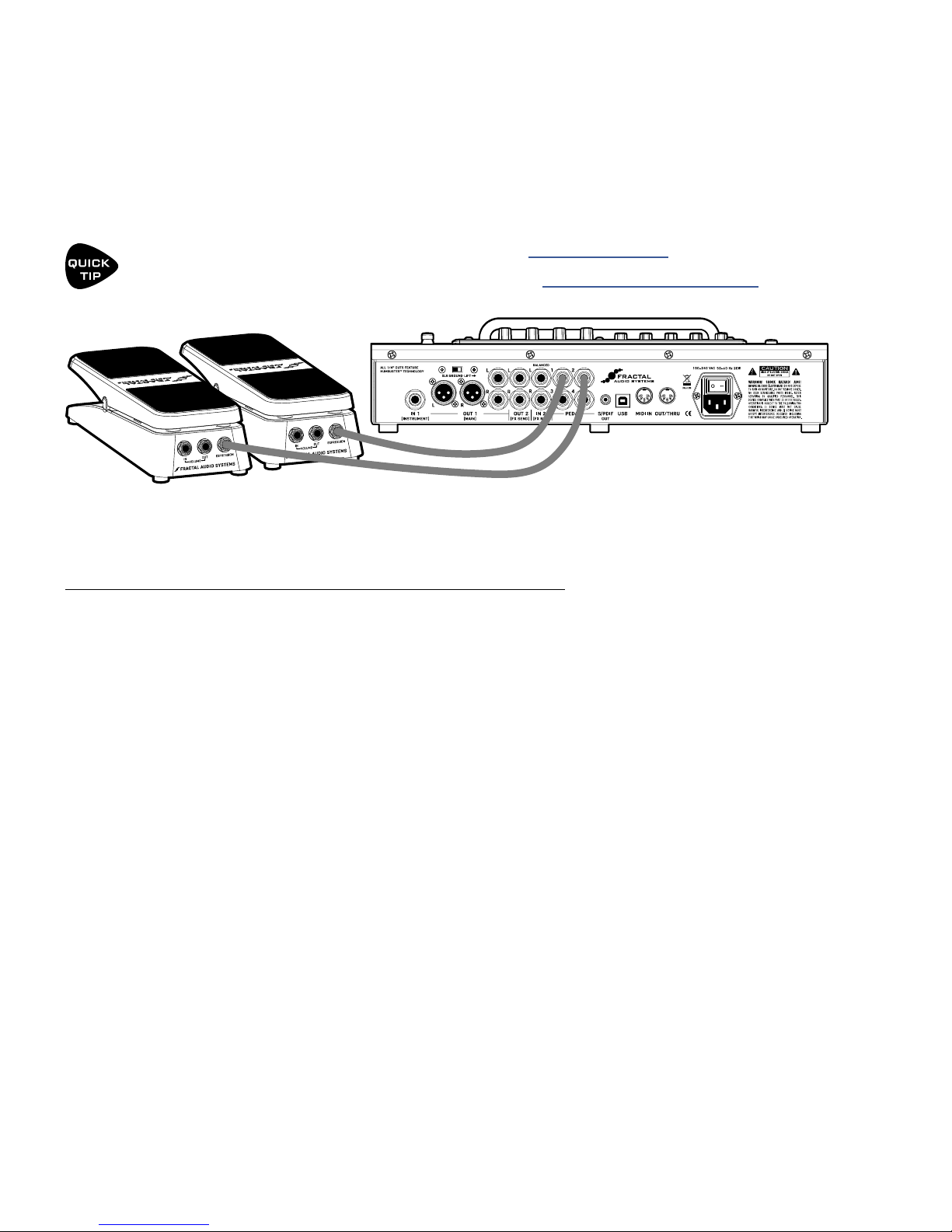
CONNECTING PEDALS & SWITCHES
Each of the four on-board PEDAL jacks of the AX8 allows you to connect one expression pedal or one
external footswitch. You can use a connected pedal or switch to change eect parameters or to operate any
of a long list of global functions, and many factory presets are ready for one or even two pedals.
Learn to assign pedals and switches to sound parameters in Section 8 Modiers.
Learn to assign pedals and switches to global functions under “I/O: Controllers Page” on p. 81.
The Fractal Audio Systems EV-1 Expression/Volume Pedal (sold separately) is ideal for the AX8.
TO CONNECT & CALIBRATE AN EXPRESSION PEDAL...
The best expression pedals for the AX8 have a linear resistance taper and a max resistance of 10kΩ to
100kΩ. Expression pedals must be used with Tip-Ring-Sleeve (TRS) cables. (If you are not familiar with TRS
cables, see the FAQ on the next page.) Connect your expression pedal to the desired PEDAL jack (1–4) with a
TRS cable, then follow these instructions to calibrate:
Press the SETUP button, followed by the #2 footswitch to select the I/O menu.
Press the PAGE button until you reach the PEDAL page.
Ensure that the pedal TYPE is set to “CONTINUOUS”.
Navigate to the PEDAL # CAL function and press the ENTER button.
Follow the on-screen instructions to perform calibration.
During calibration, you should see the “slider”
move on-screen as you move the pedal. It does
not need to reach “MAX”, but a good quality pedal
should demonstrate a wide range of motion.
18
3 SETUP GUIDE
TO CONNECT AND SET UP AN EXTERNAL FOOTSWITCH...
Footswitches are less versatile, but sometimes all you need is an on-o stomp. Any type of external switch
may be used—momentary or latching—as long as its contacts make and break the connection between tip
and sleeve on a regular 1/4" guitar cable. You do not need a TRS cable for a footswitch.
Calibration is not necessary, but you do need to set the TYPE:
Press the SETUP button, followed by the #2 footswitch to select the I/O menu.
Press the PAGE button until you reach the PEDAL page.
Set the PEDAL TYPE for your selected pedal (1–4):
When a latching (aka toggle) switch is connected, set TYPE to “LATCHING”.
When a momentary switch (such as a sustain pedal) is connected, you have two options:
Set TYPE to “MOMENTARY” and the AX8 will recognize alternate stomps
as ON and OFF, creating a “virtual” latching footswitch.
Set TYPE to “CONTINUOUS” if you want the switch to turn on
when you press, and o when you release it.
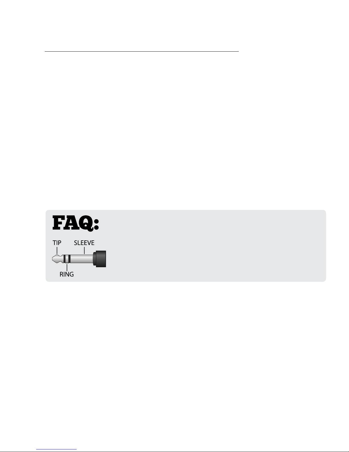
WHAT IS TRS? “TRS” stands for TIP-RING-SLEEVE and describes the
conguration of a 1/4" endplug or jack with three connectors. Normal guitar
cables are TS (Tip-Sleeve) since they lack the ring required for a third contact.
Expression pedals require TRS cables because full control voltage is transmitted
to them on one contact (the tip), while less than full voltage is returned to
on another (the ring) so the host device is able to sense and utilize the pedal
position. The third contact (sleeve) is connected to ground.
19
3 SETUP GUIDE
(Not Included)
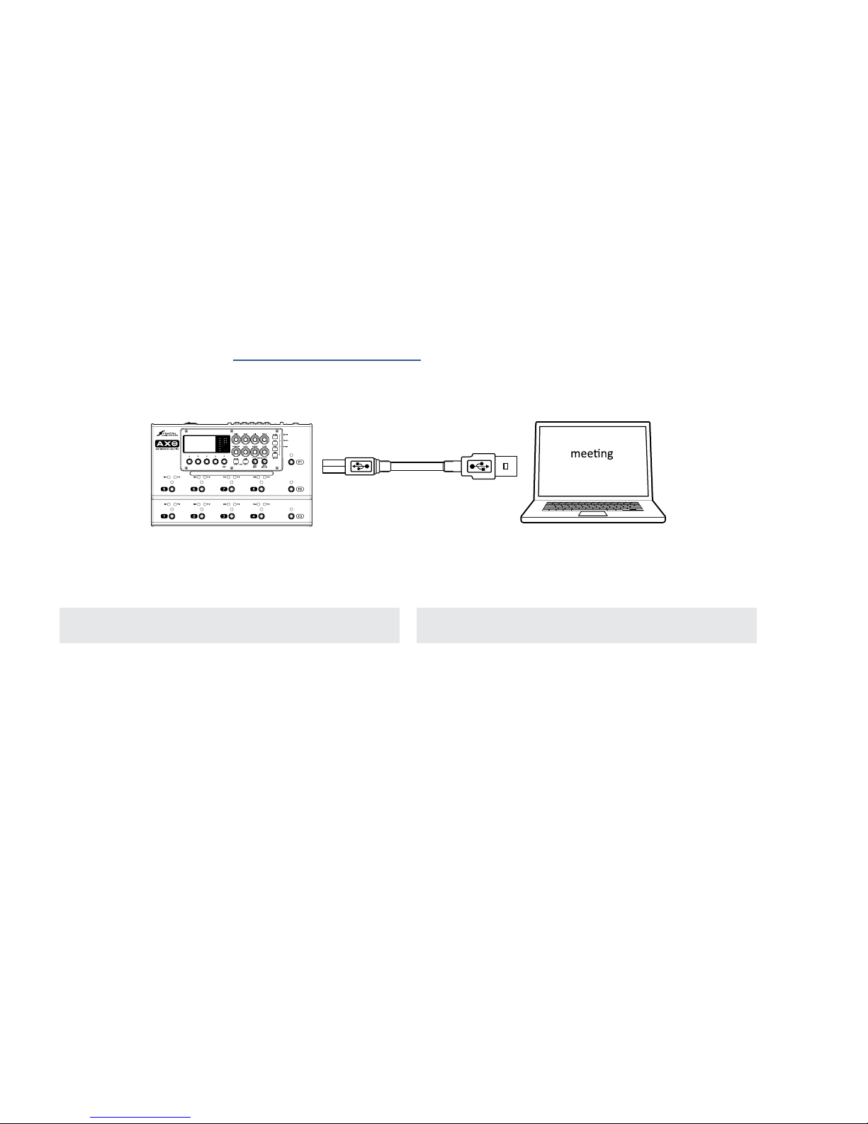
CONNECTING A COMPUTER
Connecting the AX8 to a computer via USB is optional, but it does provide some great benets. Our free
utilities are a great way to take your experience to the next level. A USB connection is also required to install
rmware updates and make or restore backups.
The rst step is to connect your AX8 to the computer with a USB cable (not provided).
No driver is required. The AX8 is plug and play.
Install Fractal-Bot™ for rmware updates or to send and receive Presets, Banks, User Cabs and System les.
Install AX8-Edit™ for a graphical way to work with AX8 presets and settings.
Find both programs at http://www.fractalaudio.com
Mac or PC
minimum
requirements
AX8 USB Cable
Mac Minimum Requirements:
OS X 10.6.8 or newer
CPU: Intel Processor
Memory: 512MB minimum
USB 2.0 Support required
Computer
Windows Minimum Requirements:
OS: WinXP (SP3), Vista (SP2), Win7 (SP1) Win8
x86 or x64 versions supported
CPU: Intel Core 2 @1.6 GHz or better,
or AMD equivalent
Memory: 1GB minimum
USB 2.0 support required
AX8-Edit
FRACTAL-BOT
20
4 FUNCTION SWITCHES
4 FUNCTION SWITCHES
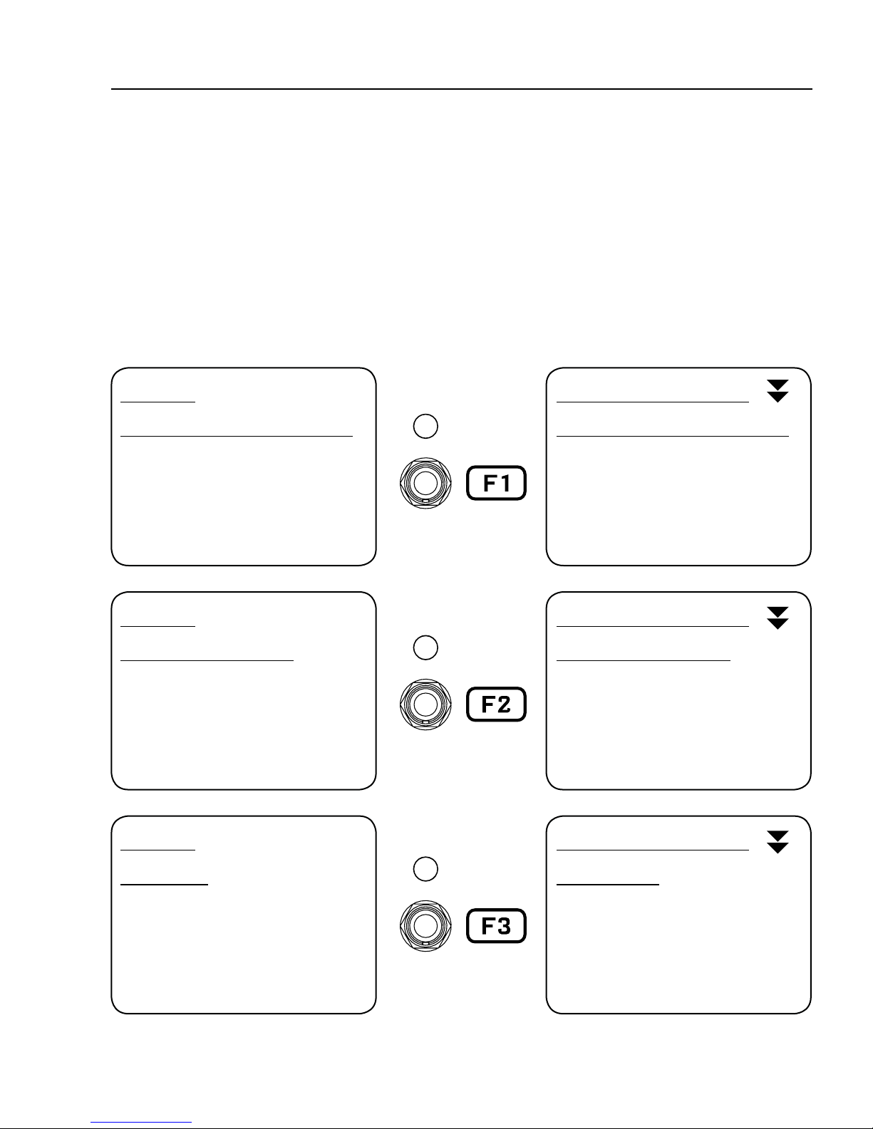
F-SWITCHES OVERVIEW
The AX8 features three assignable Function Footswitches, also known as “F-Switches” because they are
labeled F1, F2 and F3. Each F-Switch can be assigned TWO functions: one for when you TAP the switch and
the other for when you press and hold it. Default settings are detailed below:
F1 TAP
SINGLE PRESET/BANK SELECT
Use F2 and F3 to select Banks
Use 1–8 to select a Preset
After selecting a Preset, the
AX8 Returns to the Footswitch
Page for your current Preset.
F2 TAP
SINGLE SCENE SELECT
Use 1–8 to select a Scene
After selecting a Scene, the
AX8 returns to the Footswitch
Page for your current preset.
F1 PRESS & HOLD
STICKY PRESET/BANK SELECT
Same as Single Preset/Bank Select
(described at left) except that you
need to TAP the footswitch again
to exit Preset/Bank Select Mode.
The LED blinks while engaged.
F2 PRESS & HOLD
STICKY SCENE SELECT
Same as Single Scene Select
(described at left) except that
you need to TAP the footswitch
again to exit Scene Select Mode.
The LED blinks while engaged.
F3 TAP
TAP TEMPO
Used to set the AX8 Tempo.
Displays the Tempo menu, where
you can change various settings.
This menu exits automatically.
The LED blinks the tempo.
F3 PRESS & HOLD
TUNER MODE
Shows the AX8 Tuner.
Tap this switch again to
exit Tuner Mode.
The LED blinks while engaged.
21

4 FUNCTION SWITCHES
CUSTOMIZING F-SWITCHES
Over a dozen custom functions are available for the F-Switches. They’re easy to change so you can put the
perfect set of switchable modes at your feet. If you never use Tap Tempo, get rid of it! If you’ve got boots so
big you keep accidentally pressing when you only meant to tap, disable HOLD functions. Flexibility is power.
ASSIGNING FUNCTIONS...
You can assign two functions to each F-Switch: one for when you TAP the switch and one for when you
press and HOLD it down.
Press SETUP, select the Global Menu by pressing footswitch 1, and turn to the FUNCTIONS page.
Select one of the available F-Switches using the E/NAV knob. Assign a function using the A knob.
Press EXIT two times when you’re done.
AVAILABLE FUNCTIONS...
NONE – This disables the selected TAP or HOLD function for the selected F-switch.
SINGLE PRST/BANK
à Activates Single Preset/Bank Select Mode.
à The F-switch LED remains lit until you select a preset.
à The F2 and F3 switches step UP and DOWN through BANKS.
à Footswitches 1 through 8 select a PRESET in the currently selected bank.
à To exit this mode, select a preset or tap the F1 switch.
à Because this mode also requires F2 and F3, it can ONLY be assigned to the F1 switch.
STICKY PRST/BANK
à Activates Sticky Preset/Bank Select Mode.
à The F-switch LED blinks as you select any number of presets.
à The F2 and F3 switches step UP and DOWN through BANKS.
à Footswitches 1 through 8 select a PRESET in the currently selected bank.
à To exit this mode, tap the F1 switch.
à Because this mode also requires F2 and F3, it can ONLY be assigned to the F1 switch.
STICKY PRST +/-
à Activates Sticky Preset “Plus/Minus” Mode.
à The F-switch LED remains lit while you step up or down (in order) through presets.
à F2 becomes “Next Preset” and F3 becomes “Previous Preset.”
à To exit this mode, tap the F1 switch.
à Because this mode also requires F2 and F3, it can ONLY be assigned to the F1 switch.
PRESET UP, PRESET DN
à Actually two dierent functions, these can be used to create one or two dedicated
F-Switches to step up or down through your presets. In use, these are similar
to the up/down switches from Sticky Preset +/- , except that they are always
active without needing the F1 switch to turn this mode ON or OFF.
BANK UP, BANK DN
à Actually two dierent functions, these can be used to step UP or DOWN through banks.
à The currently selected preset number within the bank will be maintained when the bank changes.
22

SINGLE SCENE
à Activates Single Scene Select Mode.
à The F-switch LED remains lit until you select a Scene.
à Footswitches 1 through 8 select a SCENE within the current preset.
à To exit this mode, select a Scene or tap the F1 switch.
STICKY SCENE
à Activates Sticky Scene Select Mode.
à The F-switch LED blinks as you select any number of scenes in the current preset.
à Footswitches 1 through 8 select a SCENE within the current preset.
à To exit this mode, stomp the F1 switch again.
SCENE 1/2 TOGGLE
à Switches between Scene 1 and Scene 2.
à The F-switch LED is o for Scene 1 and on for Scene 2.
TEMPO TAP
à Allows you to tap a tempo into the AX8. (See Section 9 Tempo.)
à Also briey displays the Tempo Menu where you can set various options.
à This function cannot be assigned to HOLD.
4 FUNCTION SWITCHES
TUNER - Activates the Tuner (p. 73). The F-Switch LED blinks. To exit the tuner, tap the assigned
F-Switch. You can also open the tuner through the CONFIG page of the main menu.
LOOPER CONTROL - Activates Looper Control Mode (“The Looper Block” on p. 54).
SINGLE XY
à Activates Single X/Y Select Mode.
à The F-switch LED remains lit until you toggle one X/Y setting.
à Footswitches 1 through 8 toggle X/Y for the assigned blocks of the current preset.
à To exit this mode, toggle any X/Y setting or tap the assigned F-switch.
STICKY XY
à Activates Sticky X/Y Select Mode.
à The F-switch LED blinks as you toggle any number of block X/Y settings.
à Footswitches 1 through 8 toggle X/Y for the assigned blocks of the current preset.
à To exit this mode, tap the assigned F-switch.
IMPORTANT: If you assign an X/Y mode to any F-Switch, footswitches 1–8 will
no longer use Press & Hold to toggle X/Y. However, their main Engage/Bypass
function is then able to happen on the footswitch DOWN-STROKE instead of the UP.
Learn more about “X/Y Switching” on p. 34.
If you set the “HOLD” function of any F-Switch to “NONE”, its TAP function switch will
execute on the switch down-stroke instead of the up.
This is useful for switches assigned to PRESET UP and PRESET DN because you’ll often
want to make this kind of change right on the downbeat.
23
4 FUNCTION SWITCHES
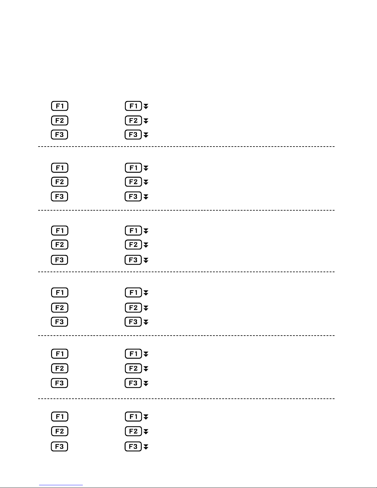
SAMPLE F-SWITCH LAYOUTS
Rather than leave this page blank, we thought it might be interesting to include a few dierent example
layouts for the F-Switches based on what the AX8 development team members set up for themselves.
TAP HOLD
Single Preset NONE
Single Scene NONE
Tempo Tuner
TAP HOLD
Single Preset Sticky Scene
Single XY NONE
Tempo Tuner
TAP HOLD
Single XY Single Preset
Single Scene Sticky Scene
Looper Control Tuner
TAP HOLD
Single XY Tuner
No “Sticky Modes”
Here we’re using an XY F-Switch. This
disables X/Y press and hold, and all
eects re on the “down-stroke”
Looper Control Mode & NO Tap Tempo.
Tempo can be programmed per-preset
so you don’t technically NEED it on the oor.
Bare bones for a performance “on the rails.”
Preset +1 NONE
Preset -1 NONE
TAP HOLD
_____________ _____________
_____________ _____________
_____________ _____________
TAP HOLD
_____________ _____________
_____________ _____________
_____________ _____________
Scene 1/2 Toggle was globally set to switch 4.
Record your favorite setups here.
24
 Loading...