

Page 1
Page 2

Page 3
Legal Notices
WARNING: To reduce the risk of fire or electric shock, do not expose
this appliance to rain or moisture.
CAUTION: To reduce the risk of fire or electric shock, do not remove
screws. There are no user serviceable parts inside. Refer servicing to
qualified service personnel.
Fractal Audio Systems Axe-Fx II Owner’s Manual. Contents Copyright © 2011 -2014. All Rights Reserved.
No part of this publication may be reproduced in any form without the permission of Fractal Audio Systems.
Fractal Audio Systems, Axe-Fx, G3 Modeling Technology (“G3”), Humbuster, Multipoint Iterative Matching and
Impedance Correction (“MIMIC”), UltraRes, Virtual Vacuum Tube (“VVT”), and Quantum and are trademarks of
Fractal Audio Systems. Manufacturer names and product names mentioned herein are trademarks or registered
trademarks of their respective owners, which are in no way associated with or affiliated with Fractal Audio
Systems. The names are used only to illustrate sonic and performance characteristics.
Important Safety Instructions
1. Obey all warnings on the Axe-Fx II and in this User Guide.
2. Keep away from sources of heat such as heat ducts, registers or appliances which produce heat.
3. Connect only to a proper AC outlet of 100–240V, 47–63 Hz.
4. Keep the power cord in good condition. Do not kink, bend, or pinch. If the cord becomes
damaged, discard and replace it.
5. If not using your Axe-Fx II for extended periods of time, disconnect from AC mains.
6. Protect the unit from rain and excessive moisture.
7. Refer servicing to qualified personnel only.
8. Do not operate the unit and obtain service if:
a. Liquids or excessive moisture enter the unit.
b. The unit operates incorrectly or performance is inconsistent or erratic.
c. The unit has been dropped and/or the enclosure damaged.
9. Prolonged exposure to high volume levels can cause hearing damage and/or loss. The use of
hearing protection in high volume situations is recommended.
Doc Q7.0
February 12, 2017
Doc Q7.0 i Doc Q7.0
Page 4

Certificate of Conformity
EN60065
(IEC 60065)
Safety requirement for mains operated electronic and related apparatus for household and
similar use.
EN 55103-1
Product family standard for audio, video, audio-visual, and entertainment lighting control
apparatus for professional use. Part 1: Emission.
EN 55103-2
Product family standard for audio, video, audio-visual, and entertainment lighting control
apparatus for professional use. Part 2: Immunity.
Fractal Audio Systems, USA, hereby declares on its own responsibility that the following products:
Axe-Fx II Digital Guitar Preamplifier and Effects Processor
Axe-Fx II Mark II Digital Guitar Preamplifier and Effects Processor
Axe-Fx II XL Digital Guitar Preamplifier and Effects Processor
Axe-Fx II XL+ Digital Guitar Preamplifier and Effects Processor
That are covered by this certificate, and marked with CE label, conform to following standards:
with reference to regulations in following directives: 73/23/EEC, 89/336/EEC.
June 2014
Clifford Chase, President
Fractal Audio Systems
EMC / EMI
This equipment has been tested and found to comply with the limits for a Class B Digital device, pursuant to part 15 of the FCC
rules. These limits are designed to provide reasonable protection against harmful interference in residential installations. This
equipment generates, uses and can radiate radio frequency energy and, if not installed and used in accordance with the
instructions, may cause harmful interference to radio communications. There is no guarantee that interference will not occur in
a particular installation. If this equipment does cause harmful interference to radio or television reception, which can be
determined by turning the equipment off and on, the user is encouraged to try to correct the interference by one or more of
the following measures:
Reorient or relocate the receiving antenna.
Increase the separation between the equipment and receiver.
Connect the equipment to an outlet on a circuit different from that to which the receiver is connected.
Consult the dealer or an experienced radio/TV technician for help.
About the Author
Matt Picone is a music technology product specialist, sound designer, creative director, and musician with over 35 years of
experience spanning guitars, amps, effects, synthesizers, software, and beyond. He has worked with artists including Dweezil
Zappa, Adrian Belew, Steve Vai, John Petrucci, the Edge, Neal Schon, Periphery, Animals As Leaders, Metallica, Scott Appleton
(Def Leppard/Rush/etc.) and more. This work is based extensively on the original Axe-Fx manual by Fractal Audio founder and
Axe-Fx creator Cliff Chase. Many thanks to our team of dedicated beta-testers, preset creators, copy-editors and proofreaders.
You may report manual corrections or suggestions in our forum at http://forum.fractalaudio.com
ii Doc Q7.0
Page 5

Foreword
Thank you for purchasing an Axe-Fx II, one of the most powerful musical instrument processors
ever produced. Please take the time to read through this manual to become acquainted with
the Axe-Fx II.
Thinking back to a date when the first Axe-Fx units rolled off the line back in 2006, it would
have been a challenge to predict the scale of what was to follow… that the product would be
such a worldwide success that we would have a hard time keeping it in stock; that musicians
would rally around the unit, from online “Axe-evangelists” to the world’s most celebrated pro
players; that we’d soon be writing the foreword to a manual for the sequel: the Axe-Fx II.
Nevertheless, the Axe-Fx II is here. Advances in technology and knowledge, along with the
shared insights of our community, have allowed us to design and produce a next-generation
product that represents a giant step forward. If you owned a Standard or an Ultra, we think
you’ll be very impressed with all the updates, additions and improvements. If you’re new to the
Axe-Fx family, this is an incredible place to start.
It has been said that the Axe-Fx “restored digital to its rightful place as the superior solution to
musical effects processing.” Every aspect of the Axe-Fx II has been designed to deliver the latest
word in this commentary. It has twice the power of the Axe-Fx Ultra (while even the older
“Standard” still has more horsepower under the hood than any competitor). For the player, this
means better sound, smarter features, and improved performance.
In 2015 we introduced the Axe-Fx II XL+, with upgraded/expanded memory and peripherals. We
think it is the best of our products ever, and we hope you agree. Now, with the new releases in
our latest generation Quantum firmware series, every Axe-Fx II sounds equally great (and
better than ever!) with accurate amp models, masterfully created virtual speaker cabs, and
effects that truly stand apart. We thank you all for your many contributions, and for choosing
Fractal Audio Systems!
—Fractal Audio Systems, January 2017
Doc Q7.0 iii Doc Q7.0
Page 6

TABLE OF CONTENTS
Table of Contents
Foreword .......................................................................................... iii
Table of Contents .............................................................................. iv
What’s New .......................................................................................1
1 Introduction ..................................................................................4
1.1 What is the Axe FX II? .............................................................................. 4
1.2 The Inventory/Grid Concept ..................................................................... 6
1.3 Connectivity and More ............................................................................. 7
2 Overview ......................................................................................8
2.1 The Front Panel ........................................................................................ 8
2.2 The Rear Panel ....................................................................................... 10
2.3 Computer Integration ............................................................................ 12
Minimum Requirements ...................................................................................................................... 12 2.3.1
Software Installation ............................................................................................................................ 12 2.3.2
Capabilities ........................................................................................................................................... 13 2.3.3
Fractal-Bot ........................................................................................................................................... 14
2.3.4
Axe-Edit ................................................................................................................................................ 14 2.3.5
3 Connections ................................................................................ 15
3.1 Setting Levels ......................................................................................... 15
3.2 The PEDAL Jack(s)................................................................................... 16
3.3 System Parameters ................................................................................ 16
3.4 Connection Diagrams ............................................................................. 17
Axe-Fx II into Self-Powered Full-Range Speakers................................................................................. 18 3.4.1
Axe-Fx II into Studio Monitors ............................................................................................................. 18 3.4.2
Axe-Fx II with Power Amp and Guitar Speakers .................................................................................. 19
3.4.3
Axe-Fx II Effects Loop ........................................................................................................................... 20 3.4.4
Axe-Fx II Digital Audio Interconnection ............................................................................................... 20 3.4.5
Axe-Fx II Four Cable Method (“4CM”) ................................................................................................. 21 3.4.6
Direct to FOH plus Real Amps on Stage ............................................................................................... 22 3.4.7
Axe-Fx II as Effects Processor Only (with Guitar Amps) ....................................................................... 23 3.4.8
Axe-Fx II as a Computer Audio Interface ............................................................................................. 24 3.4.9
Axe-Fx II XL/XL+ and MFC-101 Mark III ................................................................................................ 25 3.4.10
iv Doc Q7.0
Page 7

TABLE OF CONTENTS
Axe-Fx II XL/XL+ & MFC-101 Mark III: One Possible “Big Rig” .............................................................. 26 3.4.11
4 Basic Operation and Editing ......................................................... 27
4.1 Presets ................................................................................................... 27
4.2 The Grid ................................................................................................. 28
Inserting and Removing Blocks ............................................................................................................ 28 4.2.1
Shunts .................................................................................................................................................. 29 4.2.2
Connector Cables ................................................................................................................................. 30 4.2.3
Moving Blocks on the Grid ................................................................................................................... 32 4.2.4
Example Presets on the Grid ................................................................................................................ 33 4.2.5
4.3 Editing Sounds ....................................................................................... 35
Quick Control ....................................................................................................................................... 36 4.3.1
4.4 X/Y Switching ......................................................................................... 36
X/Y Quick Jump .................................................................................................................................... 37 4.4.1
4.5 Bypassing a Block ................................................................................... 37
4.6 Loading Effects from another Preset ...................................................... 37
4.7 Saving Changes ...................................................................................... 38
Swapping the Locations of Two Presets .............................................................................................. 38 4.7.1
5 Effects Guide ............................................................................... 39
5.1 Amplifier [AMP] ..................................................................................... 39
Amp Type ............................................................................................................................................. 39 5.1.1
Amp Preamp Page (“PRE”) ................................................................................................................... 40 5.1.2
Amp Power Amp Page (“PWR”) ........................................................................................................... 41 5.1.3
Amp Speaker Page (“SPKR”) ................................................................................................................ 42 5.1.4
Power Amp Dynamics Page (“PWR DYN”) ........................................................................................... 43 5.1.5
Amp Preamp Dynamics Page (“PRE DYN”) .......................................................................................... 44 5.1.6
Amp Dynamic EQ Page (“DYNEQ”) ...................................................................................................... 45 5.1.7
Amp Advanced Page (“ADV”) .............................................................................................................. 46 5.1.8
5.2 Cabinet [CAB] ......................................................................................... 50
User Cabs ............................................................................................................................................. 53 5.2.1
5.3 Chorus [CHO] ......................................................................................... 54
5.4 Compressor [CMP] ................................................................................. 56
5.5 Crossover [XVR] ..................................................................................... 59
5.6 Delay [DLY] ............................................................................................ 60
Mono Delay .......................................................................................................................................... 61 5.6.1
Stereo Delay ......................................................................................................................................... 62 5.6.2
Doc Q7.0 v Doc Q7.0
Page 8

TABLE OF CONTENTS
Dual Delay ............................................................................................................................................ 63 5.6.3
Ping-Pong Delay ................................................................................................................................... 64 5.6.4
Sweep Delay......................................................................................................................................... 64 5.6.5
Reverse Delay ...................................................................................................................................... 64 5.6.6
Tape Delay ........................................................................................................................................... 65 5.6.7
Delay Common Parameters ................................................................................................................. 66 5.6.8
5.7 Drive [DRV] ............................................................................................ 68
5.8 Effects Loop [FXL] ................................................................................... 70
5.9 Enhancer [ENH] ...................................................................................... 72
5.10 Feedback Send [SND] & Return [RTN] .................................................. 73
5.11 Filter [FLT] ........................................................................................... 74
5.12 Flanger [FLG] ....................................................................................... 75
5.13 Formant [FRM] .................................................................................... 77
5.14 Gate/Expander [GTE]........................................................................... 78
5.15 Graphic Equalizer [GEQ] ...................................................................... 79
5.16 Looper [LPR] ........................................................................................ 80
5.17 Megatap Delay [MGT] ......................................................................... 82
5.18 Mixer [MIX] ......................................................................................... 84
5.19 Multiband Compressor [MBC] ............................................................. 85
5.20 Multi-Delay [MTD] .............................................................................. 86
Quad Tap Delay .................................................................................................................................... 87 5.20.1
Plex Delay ............................................................................................................................................. 89 5.20.2
Plex Detune .......................................................................................................................................... 90 5.20.3
Plex Shift .............................................................................................................................................. 91 5.20.4
Band Delay ........................................................................................................................................... 91 5.20.5
Quad Series Delay ................................................................................................................................ 92 5.20.6
Ten-Tap Delay ...................................................................................................................................... 93 5.20.7
Rhythm Tap Delay ................................................................................................................................ 94 5.20.8
Diffusor ................................................................................................................................................ 95 5.20.9
Quad Tape Delay .............................................................................................................................. 95 5.20.10
5.21 Tremolo/Panner [PAN] ........................................................................ 96
5.22 Parametric EQ [PEQ] ............................................................................ 97
5.23 Phaser [PHA] ....................................................................................... 98
vi Doc Q7.0
Page 9

TABLE OF CONTENTS
5.24 Pitch Shifter [PIT] .............................................................................. 100
Detune ............................................................................................................................................... 102 5.24.1
Fixed Harmony ................................................................................................................................... 103 5.24.2
Intelligent Harmony ........................................................................................................................... 104 5.24.3
Classic Whammy ................................................................................................................................ 106 5.24.4
Octave Divider ................................................................................................................................... 106 5.24.5
Crystals ............................................................................................................................................... 107 5.24.6
Advanced Whammy ........................................................................................................................... 108 5.24.7
Arpeggiator ........................................................................................................................................ 109 5.24.8
Custom Shifter ................................................................................................................................... 110 5.24.9
5.25 Quad Chorus [QCH] ........................................................................... 111
5.26 Resonator [RES] ................................................................................. 113
5.27 Reverb [REV] ..................................................................................... 114
5.28 Ring Modulator [RNG] ....................................................................... 118
5.29 Rotary Speaker [ROT] ........................................................................ 119
5.30 Synth [SYN] ....................................................................................... 120
5.31 Tone Matching [TMA] ........................................................................ 121
5.32 Vocoder [VOC] ................................................................................... 122
5.33 Volume/Pan [VOL] ............................................................................ 124
5.34 Wahwah [WAH] ................................................................................ 125
5.35 Input Noise Gate ............................................................................... 126
Input Impedance ................................................................................................................................ 127 5.35.1
5.36 Output Mixer .................................................................................... 128
5.37 Common Mix Parameters .................................................................. 128
6 Global Blocks ............................................................................. 131
6.1 Introduction ......................................................................................... 131
6.2 Using Global Blocks .............................................................................. 131
Saving to a Global Block ..................................................................................................................... 132 6.2.1
Loading and Linking a Global Block .................................................................................................... 133 6.2.2
Loading Global Blocks without Linking .............................................................................................. 134 6.2.3
Unlinking Preset and Global Blocks ................................................................................................... 135 6.2.4
Backing Up/Sharing Presets Containing Global Blocks ...................................................................... 135 6.2.5
7 Modifiers & Controllers ............................................................. 136
Doc Q7.0 vii Doc Q7.0
Page 10

TABLE OF CONTENTS
7.1 Introduction ......................................................................................... 136
7.2 Creating a Modifier .............................................................................. 136
Transformations ................................................................................................................................. 138 7.2.1
Scale and Offset ................................................................................................................................. 139 7.2.2
Damping ............................................................................................................................................. 140 7.2.3
Auto Engage ....................................................................................................................................... 140 7.2.4
Program Change Reset ...................................................................................................................... 141 7.2.5
7.3 Control Sources .................................................................................... 141
LFO1 & 2 ............................................................................................................................................ 141 7.3.1
ADSR 1 & 2 ......................................................................................................................................... 142 7.3.2
Sequencer .......................................................................................................................................... 143 7.3.3
Envelope Follower ............................................................................................................................. 143 7.3.4
Pitch Detector .................................................................................................................................... 144 7.3.5
Manual Knobs .................................................................................................................................... 144 7.3.6
Scene Controllers ............................................................................................................................... 144 7.3.7
External Controllers ........................................................................................................................... 144 7.3.8
8 Global Parameters ..................................................................... 145
8.1 Configuration Parameters .................................................................... 145
8.2 Output Parameters .............................................................................. 146
8.3 Custom Scales ...................................................................................... 147
9 Input/Output Parameters .......................................................... 148
9.1 Input Parameters ................................................................................. 148
9.2 Audio Parameters ................................................................................ 148
9.3 MIDI Parameters .................................................................................. 150
9.4 Control Parameters .............................................................................. 152
9.5 Pedal Parameters ................................................................................. 154
9.6 X/Y Quick-Jump Assign ......................................................................... 154
10 Utilities ................................................................................... 155
10.1 LCD Contrast ...................................................................................... 155
10.2 Preset Utilities ................................................................................... 155
10.3 Status Meters .................................................................................... 155
10.4 VU Meters ......................................................................................... 156
viii Doc Q7.0
Page 11

TABLE OF CONTENTS
10.5 Reset System ..................................................................................... 156
10.6 IR Capture ......................................................................................... 156
10.7 Firmware ........................................................................................... 156
11 Tuner ...................................................................................... 157
12 Tempo .................................................................................... 158
12.1 Setting the Tempo ............................................................................. 158
12.2 Synchronizing Sound Parameters ...................................................... 158
12.3 Tempo to Use .................................................................................... 159
12.4 Auto Delay ........................................................................................ 159
12.5 Metronome ....................................................................................... 159
13 Backing Up and Restoring ........................................................ 160
13.1 Onboard ROM Backup and Restore ................................................... 160
14 Firmware Updates................................................................... 162
Axe-Fx II XL/XL+ Failsafe Firmware .................................................................................................... 162 14.1.1
Firmware Compatibility ..................................................................................................................... 162 14.1.2
15 Troubleshooting ...................................................................... 163
16 Appendix ................................................................................ 165
16.1 Table of Amp Types ........................................................................... 165
16.2 Table of Cab Types ............................................................................ 169
16.3 Loading User Cab IRs ......................................................................... 170
16.4 Shortcuts Overview ........................................................................... 171
16.5 60-Second Edit Guide ........................................................................ 172
16.6 Understanding Preset Size Limits ....................................................... 173
16.7 LFO Waveforms, Duty, and Phase ...................................................... 174
LFO Phase ........................................................................................................................................... 174 16.7.1
16.8 Tempo Cross Reference ..................................................................... 175
16.9 Mono and Stereo............................................................................... 176
16.10 Mixology ......................................................................................... 177
Doc Q7.0 ix Doc Q7.0
Page 12

TABLE OF CONTENTS
16.11 Humbuster™ Technology ................................................................ 178
16.12 Setting up a Wah Pedal ................................................................... 179
Using the Onboard Pedal Jack ....................................................................................................... 179 16.12.1
Using an Expression Pedal on an MFC-101 .................................................................................... 180 16.12.2
16.13 Setting Up Spillover ........................................................................ 181
Within a Single Preset .................................................................................................................... 181 16.13.1
Across Different Presets................................................................................................................. 181 16.13.2
16.14 Using Send and Return ................................................................... 182
Creating Feedback Loops .............................................................................................................. 182 16.14.1
Extending the Length of Effect Chains ........................................................................................... 183 16.14.2
16.15 Scenes ............................................................................................ 184
Selecting Scenes ............................................................................................................................. 185 16.15.1
SETTING UP SCENES ....................................................................................................................... 185 16.15.2
SAVING SCENES .............................................................................................................................. 185 16.15.3
SPILLOVER IN SCENES .................................................................................................................... 186 16.15.4
SCENES AND MIDI .......................................................................................................................... 186 16.15.5
MFC-101 Scene Features ............................................................................................................... 187 16.15.6
Table of CC# Values for Scene Select ............................................................................................. 187 16.15.7
16.16 Modifier Power! ............................................................................. 188
16.17 Glossary & Resources ..................................................................... 189
16.18 Axe-Fx II Bank & Preset Numbers Table .......................................... 192
16.19 Factory Default Settings .................................................................. 193
17 Specifications .......................................................................... 195
17.1 Axe-Fx II XL/XL+ Specifications .......................................................... 195
17.2 Axe-Fx II Mark II Specifications .......................................................... 196
17.3 Midi Implementation Chart ............................................................... 197
Warranty ....................................................................................... 198
End User License Agreement .......................................................... 199
x Doc Q7.0
Page 13

WHAT’S NEW
What’s New
Years of R&D at Fractal Audio Systems have yielded our next-generation product, the Axe-Fx II. With twice the
power of our former flagship the Ultra, the Axe-Fx II unveils new state-of-the-art algorithms and an innovative
array of great hardware and software features and improvements. This all-in-one preamp/effects processor
recreates complete signal chains—stompboxes, amps, cabs, mics, studio effects, and more—with unprecedented
power, flexibility, and control. The Axe-Fx II takes "real amp tone and feel" to the next level, offering the latest
word on restoring digital to its rightful place as the superior solution for guitar processing.
Twice the Processing Power
Our philosophy is never to cut corners on processing power. Our state-of-the-art algorithms require a powerful
platform on which to operate, so the Axe-Fx II features two 600 MHz dual-core Analog Devices TigerSHARC™
Digital Signal Processors working in tandem. One is devoted solely to amp modeling while the other handles
effects and system tasks. Mated to the processors is double the RAM of previous Axe-Fx products. The Axe-Fx II is
by far the most powerful instrument processor ever created, with more raw, real-time audio processing
horsepower than anything available at any price. Yet, unlike power-hungry PCs, it consumes less than 40W.
Quantum™ Amp Modeling™ with Virtual Vacuum Tube™ Technology and MIMIC™
All this power would be useless without superior algorithms to take advantage of it. Years of research have yielded
Quantum Amp Modeling Technology, comprising major breakthroughs in both preamp and power amp modeling.
Quantum is the pinnacle of our multi-generational amp modeling and a complete departure from the static
waveshaping technology used by other products. It entails digital replicas of vacuum tubes, complete with time,
frequency, and level dependencies. This creates a level of dynamic realism in a class of its own. Like our “G3”
modeling before it, Quantum™ also models the entire power amp, including the phase inverter, power tubes,
output transformer, power transformer, choke, filter caps, and more. The results are amazing: tight bass, powerful
midrange, silky highs, plus highly expressive touch sensitivity.
Our amp models are the result of thousands of hours of incredibly detailed analysis of the actual amps that
inspired them. We spent a small fortune searching out and purchasing vintage and modern amplifiers to add to our
reference collection. Quantum™ is a significant advancement in amplifier simulation unmatched by any other
product at any price point.
Improved Speaker Simulation, On-board IR Capture and UltraRes™
The Axe-Fx II cabinet simulator supports our patent-pending UltraRes™ Impulse Response format, with 170+*
factory IRs including creations by Fractal Audio Systems, ML Sound Lab, OwnHammer, RedWirez, Jay Mitchell,
James Santiago, TheAmpFactory, and John Petrucci of Dream Theater — plus 1024* "USER CAB" memory locations
and built-in tools to capture your own IRs from a real speaker cab. UltraRes™ is a proprietary technique that
enhances the spectral resolution of an IR without adding CPU burden or storage requirements.
Tone Matching™ to “Clone” any Tone
The Axe-Fx II features a Tone Matching block with the capability to match the sound of a real or recorded amp. It
does this by analyzing the difference between the sound of your preset (the “local” signal) and a “reference”
(usually the signal from one or more mics/preamps on a real amp, or a high quality recording.) Tone matching
eliminates guesswork to create exact “clones” of your favorite tone. A separate Tone Match Mini-manual is
provided.
*The Axe-Fx II Mark 2 has only 130+ factory IRs and 100 user IR slots.
Doc Q7.0 1
Page 14

WHAT’S NEW
Easier-to-Use Front Panel Features
A new, custom-designed 160x80 backlit LCD provides improved readability and more spacious screen layouts. In
addition to the main VALUE knob, new QUICK CONTROL knobs provide hands-on access to four additional onscreen parameters. Many block types including Amp, Cab, Chorus, Drive, Delay, Flanger, Phaser, Pitch, Reverb, and
Wahwah—are now equipped with two fully independent parameter sets called “X” and “Y.” The X/Y switching
feature allows one block to have all of its settings switched at the touch of a button (during editing) or via MIDI
remote control (during a performance). The X and Y buttons also double as user-definable “quick jump” keys that
can be set up to open the EDIT menus of any two blocks without going through the grid.
Axe-Fx II/Computer Integration with Onboard USB
The new onboard Audio Class 2.0 compliant USB interface provides great capabilities for recording and computer
integration. You can record high quality 48k/24-bit audio from the Axe-Fx II directly to the computer, play or
process audio tracks from the computer through the Axe-Fx II, and use two-way high-speed MIDI without a 3rdparty interface. On USB 2.0 or better systems, you can simultaneously record both the main processed stereo outs
and a pair of dry channels for easy re-amping.
New I/O Capabilities and Less Noise
All rear analog inputs are now balanced, as are the onboard XLR outputs. The ¼" unbalanced outputs feature our
Humbuster™ technology, which senses and subtracts the ground noise of equipment connected when you use a
special Humbuster™ cable. This can provide up to 20 dB reduction in ground noise without resorting to dangerous
"cheater plugs" or expensive isolation transformers.
We designed the Axe-Fx II with the “Four-Cable Method” in mind. Special analog processing keeps the noise floor
even lower on outputs designed to be connected to the front of an amplifier.
The front panel input uses a proprietary circuit and dedicated A/D converter for astonishingly low noise. The
original Axe-Fx was hailed for its low-noise performance; the Axe-Fx II provides an almost 10 dB SNR improvement
with the same pristine quality. The XL+ has the lowest noise levels yet. A high-quality headphone jack is also
provided.
Designed for Unity Gain
The Axe-Fx II uses digitally controlled potentiometers to operate as a unity-gain device irrespective of the input
trim controls. Simply set the input trims with the LED input meters and you are done. Another benefit of this
technique is that Amp and Drive blocks are unaffected by trim settings.
Improved Digital I/O
In addition to its USB interface, the Axe-Fx II sports SPDIF and AES input and output connectors. 7-pin MIDI In and a
selectable MIDI Out/Thru jack are provided for interconnection with other MIDI-controllable equipment.
Built for MFC-101 and FASLINK™
Both the XL and the Axe-Fx II Mark II feature an EtherCON port for connecting an MFC-101 MIDI Foot Controller
via network cables (the original Axe-Fx II has an Ethernet port only). The Axe-Fx II XL and XL+ also feature an
onboard FASLINK™ port for connecting an MFC-101 Mark III over a standard XLR cable. FASLINK™ carries power
(without the need for a wall-wart) and bi-directional communication between the two units. Don’t worry if you
own an MFC-101 original or Mark II—an optional FASLINK™ adapter allows you to use this new connection
standard. A MIDI port for use with 7-pin phantom power or 5-pin MIDI cables (for connecting 3rd party MIDI
interfaces or pedalboards, for example) is also provided.
2 Doc Q7.0
Page 15

WHAT’S NEW
New FX Processing Features and Enhancements
The effects-processing capabilities of the Axe-Fx II have been vetted and endorsed by some of the most
discriminating players in the world. The sound and features of our effects provide extremely authentic
representations of many classic originals, plus the range to take you where no tone has gone before. Now, with a
TYPE control to instantly set all other parameters, it is easier than ever to dial in classic settings on many effect
blocks. “Types” include tape and analog "bucket brigade" delay effects, “script" and "block" logo phasers,
“dimension” chorus, jet flanger, vibe phaser, many classic wah pedals, whammy, and too many more to list here.
Share Settings Across Multiple Presets with Global Blocks
Those familiar with “Global Amps” from previous Axe-Fx products will appreciate Global Blocks. Those new to AxeFx products will appreciate how this feature allows centralized control of a preset collection. You can save any
effect “block” to a special memory area, then load it into multiple presets with a "link" to keep all copies
synchronized to the master. You can even update the master from any linked instance. Should you choose to
remove a link, this leaves both the original and the new copy fully independent of each other.
Axe-Fx II XL/XL+ New Features
This manual covers both the Axe-Fx II Mark II and the newer Axe-Fx II XL and XL+. All Axe-Fx II units have the same
DSP and amp modeling capabilities, but the XL offers the additions of expanded memory and peripherals as
detailed below:
Built-in FASLINK™ port for connection to MFC-101 Mark III over conventional XLR cables.
Dedicated MIDI IN, OUT, and THRU jacks (vs. shared OUT/THRU in the Mark II).
Two onboard PEDAL jacks (vs. one in the Mark II).
Primary VALUE entry via optical encoder with a lifespan of 1,000,000+ rotations.
“Secret Sauce III” instrument input features an even lower noise floor.
128 Mb of non-volatile Super-FLASH memory allows for storing 768 presets and 1024 user cabinets, plus
copious memory reserves for future expansion (384 presets and 100 cabs on the original/Mark II)
Double-capacity preset size allows for expanded functionality including X/Y switching on more blocks and
possible future implementation of more effect instances per preset.
Built-in backup firmware allows recovery in the event of complications during update.
Backward compatibility with Axe-Fx II Mark I/II presets via Axe-Edit software.
The XL+ has an even lower noise floor and a sharper, brighter display.
Improvements and Enhancements, plus More to Come...
Aside from the many features covered in this brief introduction, there are many more things in the Axe-Fx II that
we hope will make it one of the most exciting and rewarding products you have ever owned. The upgradeable
firmware of our products means that we are able to offer free updates in the form of easy-to-install downloads.
These include exciting improvements to amp modeling quality, new models, cabs, effects, and more.
Doc Q7.0 3
Page 16

INTRODUCTION
1 Introduction
What is the Axe FX II? 1.1
The Axe-Fx II is an advanced digital preamp and effects processor for guitar, bass, and other musical instruments. It
replaces amps, speakers, microphones, stompboxes, studio processors, and more. It is an all-in-one, end-to-end
great tone solution in a single black box.
Inside, a virtual environment allows you to build your dream rig (hundreds of them, in fact). Choose from an
inventory of hundreds of classic and innovative components. Select and arrange things any way you like, limited
only by the unit’s ample CPU resources and your imagination. “Dial in” your signature sound using basic controls,
or go deeper with advanced parameters, then save presets for instant recall when playing, performing, or
recording.
The sound is of uncompromising quality, due both to extremely high standards of hardware design and to our
advanced proprietary software algorithms. The Axe-Fx II, like its predecessors, asserts that digital has reclaimed its
birthright as the superior solution for musical instrument processing. Words fall short. You only need to plug in and
play to realize that this is “the real deal.”
A Word on Modeling
You may have noticed that the Axe-Fx II is not typically described as a “modeler.” This is not to diminish its debt to
heritage; on the contrary, we’ve done thousands of hours of deep analysis of the greatest amps, cabs, and effects
of all time. In fact, amps and pedals, their vacuum tubes and other components, plus speaker cabs and many
effects, are painstakingly replicated to perform exactly like the originals. But while the unit includes emulations
based on specific product types, it goes well beyond simply presenting models—with their limited controls,
features, and sounds—to offer a do-it-yourself modeling platform. If it’s models you want, we can give them to
you, but why stop there?
The Axe-Fx II removes limits instead of recreating them. Take our Wahwah effect, for example. You might just plug
in and start cryin’, or you could tune the pedal sweep, tweak the resonance, overdrive the circuit, and tailor the
sound to your exact wishes. Try the Plexi. Dial it in just right. Then open things up and hear what happens when
you drop in the tonestack from a modern Rectifier (all it takes is one turn of a knob to make the change). There are
hundreds more ways that the sound can be customized. Rediscover your all-time favorites, or go crazy creating
sounds you only wished someone would put in a product. And you don’t need to be an engineer to do so, as the
unit is extremely user-friendly.
You are not alone in the quest for tone, either. The Fractal Audio online community has amassed a wealth of
knowledge and is ready to share expertise on every subject, from the deviling details of differently dated diodes in
dilapidated distortions to how to set up your favorite artist’s “exact gear used in the exact order with the exact
settings for the first half of the second bridge of the third bonus track off the re-master.”
In comparison to its predecessors, the Axe-Fx II has some great new capabilities as an effects modeler. Just as our
previous products allowed you to select, for instance, a “TYPE” of Amp, Cab, or Drive, now the Chorus, Delay,
Flanger, Phaser and other effects include a control to automatically dial in all-time favorites—settings like
4 Doc Q7.0
Page 17

INTRODUCTION
“dimension chorus”, “tape delay”, “analog flanger”, “script 90 phaser”, and many more. Once you make a
selection, however, you can go beyond the model. With deep recreations of the intricacies and interactions behind
great tone, we create not only a sample or profile but a multidimensional whole enchilada. Again, just plug in and
hear it for yourself.
To re-pose the original question then, what is the Axe-Fx II?
The Axe-Fx II is the new flagship processor from Fractal Audio, with far more power and many more capabilities
than the former heavyweight champion, Axe-Fx Ultra—twice the DSP in fact, allowing it to deliver far more
detailed amp modeling, plus numerous other upgrades. It contains our best-ever guitar amplifier simulation and
effect technology—state-of-the-art algorithms designed to sound and feel like the real thing. It is a fully routable,
fully programmable, real-time controllable, multi-effects processor offering the utmost in sound quality, with
unrivaled flexibility and control options. It is a modeling platform upon which you can create any number of
incredible guitar tones—able to replace entire rigs of traditional gear with a single black box. Let’s take some of
these concepts a bit further:
Routable: Place effects freely in any order and layout—series, parallel, or complex networks, including feedback
loops and external send and return, at any point in the signal chain.
Programmable: Every effect has a full complement of parameters offering desirable features and tremendous
range. Gone are the limits of processors with restrictive options or little-to-no depth.
Controllable: Many parameters—including all the usual expression pedal suspects and every effect bypass
switch—can be operated remotely via MIDI, offering great real-time performance control capabilities. You can map
control curves, assign multiple parameters at once, tap powerful global controllers, and much more.
Multi-Fx: The Axe-Fx II offers all the classic effects plus a few new ones. The massive “effects inventory” allows any
preset to use two or more of almost every effect block type, so you can build huge virtual rigs. In addition, many
effects now include X/Y states so you can instantly swap one set of settings for another without changing presets.
Almost all the effects in the Axe-Fx II process in full stereo.
Utmost Quality: Sound quality is our first-and-foremost criterion for the success of the Axe-Fx II. This shows in the
hardware design and in every detail of our proprietary natural processing software algorithms. Many of these
replicate patterns that occur in nature (thus our company name of Fractal Audio Systems). The amp simulations
use unique, dynamic, non-linearity generators that produce smooth, even-ordered harmonics, giving a depth to
the sound that other processors lack. Our effects have been vetted and championed by some of the world’s most
demanding and discriminating players.
Rig Replacer: Having everything in one box has some great advantages, especially when that box is as powerful
and versatile as the Axe-Fx II. In addition to being able to replace big rigs outright, this tightly integrated, unified
system offers certain fringe benefits. No longer does changing a drive pedal mean fighting with cables half-an-inch
too short. No longer must you labor over deciding which amps your tour’s budget will or won’t allow you to ship or
handle. Gone are the headaches and hassles of systems of so many boxes strung together with so many wires,
prone as they are to failure and noise. And let’s say a small meteor hits the stage and obliterates your Axe-Fx II:
you can literally restore to a new unit during the intermission and be up and running again for the next set.
Finally, after you’ve replaced your entire rig, the Axe-Fx II lets you continually re-invent it without ever touching
Velcro, rack screws, or your credit card.
Doc Q7.0 5
Page 18

INTRODUCTION
The Inventory/Grid Concept 1.2
In the real world, we are limited by the equipment we own and by the fact that building a rig requires making
commitments. On the Axe-Fx II, these limitations are lifted, with the ability to tap a vast inventory of virtual amps,
cabs, effects, mixers, and more. You have the freedom to set them up, dial them in, save them as presets, and then
do it all again, as often as you like.
Axe-Fx II presets are created by selecting components—like amps, cabs, or effects—from an inventory, and placing
them as “blocks” into the slots of a 12×4 “grid.” As with their real-world components, blocks must be connected
together using “cables”—virtual ones in this case. Blocks in adjacent columns may be connected directly together,
with splits and merges as needed. Passive “shunts” carry signal through otherwise empty grid spaces.
Figure 1-1 – The Inventory/Grid Concept
(Note: Seven empty columns were removed from the illustration and are represented by •••)
The figure above presents a stylized example of an Axe-Fx II preset. The INPUT is routed through a SHUNT to feed a
“WAH” block. (The shunt has no effect on the sound and is shown only to introduce the concept of its use.) The
WAH block is connected to an “AMP” block (we might set its type to “Plexi Normal”), which in turn feeds a “CAB”
(one of the many “4x12” options, perhaps). This is routed to a reverb (“REV”) and then to the OUTPUT.
The size of a preset is limited only by the grid structure, block inventory, and total processing power or “CPU”.
You’ll be pleased to discover that there is enough CPU power to allow large and complex creations.
6 Doc Q7.0
Page 19

INTRODUCTION
Amp (×2)
Filter (×4)
Mixer (×2)
Reverb (×2)
Cab (×2)
Feedback Return
Multiband Compressor (×2)
Ring Modulator
Chorus (×2)
Feedback Send
Multi-Delay (×2)
Rotary (×2)
Compressor (×2)
Flanger (×2)
Tremolo/Panner (×2)
3-Voice Synth (×2)
Crossover (×2)
Formant
Parametric EQ (×4)
Tone Matching
Delay (×2)
Gate/Expander (×2)
Phaser (×2)
Vocoder
Drive (×2)
Graphic EQ (×4)
Pitch Shifter (×2)
Volume/Pan (×4)
Effects Loop
Looper
Quad Chorus (×2)
Wahwah (×2)
Enhancer
Megatap Delay
Resonator (×2)
Shunt (36)
The subject of creating and modifying presets on the grid is covered in detail in section 4: Basic Operation and
Editing (p.27). The inventory of blocks available to every Axe-Fx II preset is listed below:
In addition to the blocks listed above, each preset also includes a programmable Input Noise Gate (p. 125) and an
Output Mixer (p. 128). Of course, having components on the grid is just the beginning. Every block can be edited,
with parameters representing all the basic knobs you would expect to find, and advanced menus for deep control.
See the Effects Guide (p. 39) for more detail on blocks and their parameters.
A powerful new feature of the Axe-Fx II allows you to maintain your own collection of Global Blocks (p.131) that
can be inserted and then kept synchronized across multiple presets.
Twenty-two different Modifiers & Controllers (p. 136) are provided to automate or remotely control various
parameters in any preset. These are LFO 1, LFO 2, ADSR 1, ADSR 2, Envelope, Pitch Detector, Sequencer, Manual
A/B/C/D, and External 1–12.
Connectivity and More 1.3
The grid and effects inventory may be the centerpiece of the Axe-Fx II, but it is the powerful connectivity and
companion features that allow the system to be so much to so many. The hardware itself is covered in Section 2:
Overview (p. 8), which also details the new USB features for Computer Integration (p. 12). Rig design is covered in
Section 3: Connections (p. 15), where many diagrams are included.
Configuration and connectivity on the Axe-Fx II are managed with a number of user-specifiable options, listed and
described in Section 8: Global Parameters (p. 145), and Section 9: Input/Output Parameters (p. 148). Meanwhile,
Section 10: Utilities (p. 155) can fill out your understanding of functions related to general use and maintenance.
Finally, Sections 11 through 14 cover the Tuner (p. 157) and Tempo (p.158) functions, plus the basics of Backing
Up and Restoring (p. 160) and Firmware Updates (p. 162).
My Head Hertz…
As even this introduction shows, the Axe-Fx II contains a world of possibilities. Only the precise terminology of
audio engineering allows the very communities of musicians, engineers, and others to use and enjoy this powerful
device. In case you want to familiarize yourself with pro audio terms and jargon, the Appendix is filled with useful
material, including a Glossary (p. 184). It is followed by Specifications (p. 198) and your Warranty (p. 195).
Doc Q7.0 7
Page 20
OVERVIEW
2 Overview
Review the following to familiarize yourself with the hardware features of the Axe-Fx II.
The Front Panel 2.1
The front panel shown is that of the Axe-Fx II XL. It is functionally identical to that of the Axe-Fx II Mark II.
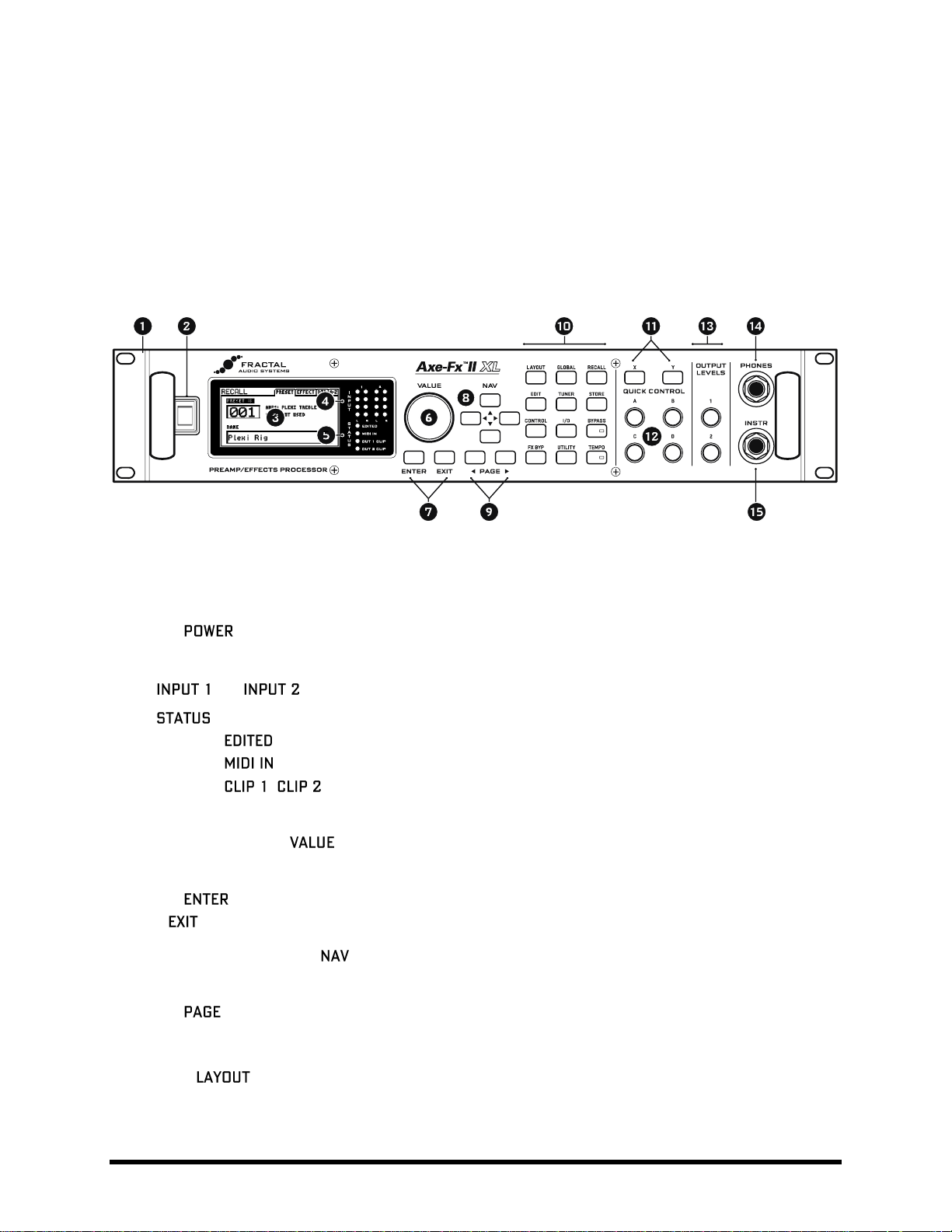
Figure 2-1 – The Axe-Fx II Front Panel
1. The Axe-Fx II is housed in a powder-coated steel enclosure with an anodized aluminum faceplate.
Dual front handles allow easy rack mounting and removal.
2. The Switch turns the unit on or off.
3. The 160 × 80 pixel LCD is where all menu and function screens are displayed.
4. and LED meters display the levels of incoming signals. See p. 15 for more detail.
5. LEDs communicate important events:
– This LED is lit when any change has been made to the current preset.
– This LED is lit while data is received at the MIDI IN port.
, – These flash briefly whenever the signal level at the corresponding output
causes the D/A converter to clip. Section 3.1 on p. 15 has more information on Setting Levels.
6. In RECALL mode, the wheel selects and loads presets as it is turned.
In edit or menu screens, it changes the value of the selected parameter.
7. The button executes commands, commits changes, accesses sub-menus, and more.
works for cancel, escape, and various other functions.
8. In RECALL mode, the four buttons select and load presets. Up = +1; Down = -1; Left=-10; Right =+10.
In edit or menu screens, these are used to select between on-screen parameters or options.
9. The buttons step through menu pages, shown as tabs at the top of the display.
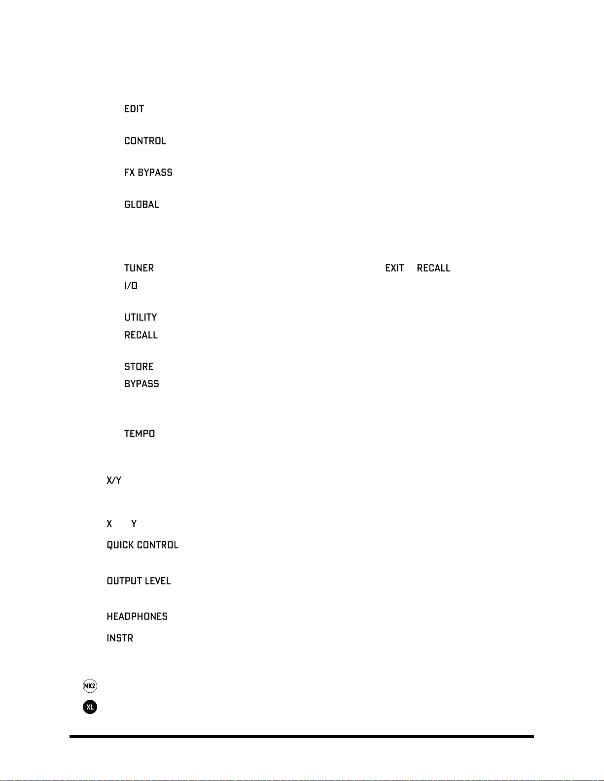
10. The 12 main front panel menu/function buttons are listed below.
– This menu contains four pages: EDIT, MOVE, GATE, and MIX.
EDIT contains the grid where presets are created by inserting blocks and cables (p. 27).
MOVE has various utilities for moving preset components on the grid (p. 32).
8 Doc Q7.0
Page 21
OVERVIEW
INPUT/GTE contains parameters for the Noise Gate and Instrument input impedance (p. 125).
OUTPUT page contains a mixer for overall level control of a preset (p. 128).
– Select any block on the layout grid and press this button to open its EDIT menu.
Press repeatedly to cycle through EDIT menus of all blocks in the preset (top-to-bottom, left-to-right).
– This menu contains pages for seven of the internal controllers available to every preset,
plus a Modifiers overview screen. See Modifiers & Controllers on p. 136 for details.
– This button toggles the bypass state of the currently selected block (p. 37).
Double click BYPASS in any block EDIT menu to access SAVE/LOAD GLOBAL BLOCKS (p. 131).
– This menu contains four pages: CONFIG, OUT1, OUT2, and SCALES. See p. 145 for details.
CONFIG contains parameters that globally affect the sound of all presets.
OUT1 and OUT2 each hold a 10-band graphic EQ and master GAIN control for the given outputs.
SCALES allows the creation of custom harmonies for use with the pitch shifter block.
– Engages the tuner (p. 157) and displays its menu. Press or to close.
– Contains six pages used to configure the various input and output options of the Axe-Fx II.
See p. 148 for details.
– This menu contains various utility functions. See p. 155 for details.
– Enters RECALL mode, the main operating mode for use during musical performance.
The Axe-Fx II always defaults to RECALL mode when you power it on.
– Enters the STORE menu where you can save, rename, or swap presets. See p. 37 for details.
– Bypasses the Axe-Fx II, routing the input directly to the output, defeating all processing,
lighting the BYPASS LED and showing a flashing on-screen warning. Press again to un-bypass.
Double-clicking the BYPASS button in any block EDIT menu initializes that block to default settings.
– Flashes the current tempo on its built-in LED. You can also tap this button once to enter the
TEMPO menu, or two or more times to set a new tempo. The tempo can also be entered using a
remote switch or set via MIDI. See p. 158 for more information about Axe-Fx II tempo control.
11. – On the Axe-Fx II, certain effects offer two fully independent sets of settings, called “X” and “Y”.
Think of them like two different “channels” for a given amp or effect. You can switch between X and Y to
access different sound settings without changing presets (see p. 36).
and buttons perform other functions as well. See section 4.4 on p. 36
12. – The four Quick Control knobs, A, B, C, and D, perform different functions depending
on what Axe-Fx II screen or menu is shown. See section 4.3.1 on p. 36 for more information.
13. – These controls set the output levels of OUTPUT 1 and OUTPUT 2 (“FX Send”). See
section 3.1 on p. 15 for information on setting levels. OUTPUT 1 also controls headphone jack levels.
14. – Connect stereo headphones here to monitor OUTPUT 1 L+R.
15. – Plug your instrument into this Instrument Input Jack, designed specifically for use with electric,
acoustic, and bass guitars. Plugging a line-level device into this input may cause clipping of the input
amplifier and is not recommended.
The Axe-Fx II Mark II features “Secret Sauce II” instrument input for a low noise floor.
The Axe-Fx II XL/XL+ features “Secret Sauce III” instrument input for an even lower noise floor.
Doc Q7.0 9
Page 22
OVERVIEW
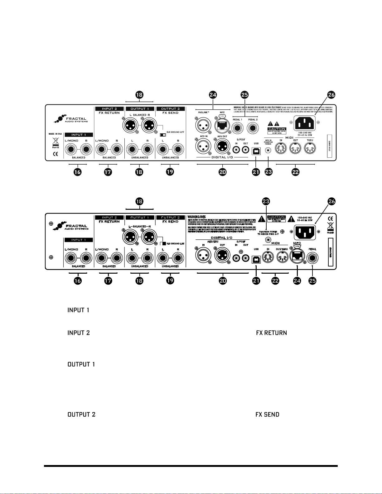
The Rear Panel 2.2
The following section details the rear panel of the Axe-Fx II. Please note differences between the Mark II and XL
models in numbered areas 22 (MIDI), 24 (MFC and FASLINK™) and 25 (PEDALS).
Figure 2-2 The Rear Panel of the Axe-Fx II XL+
Figure 2-3 The Rear Panel of the Axe-Fx II Mark II
16. Left/Mono and Right, Balanced (1/4” Tip-Ring-Sleeve) Jacks – Connect line-level input sources
to these jacks, being sure to set the INPUT 1 LEFT SELECT to REAR in the I/O menu (p. 148).
17. – Left/Mono and Right, Balanced (1/4” Tip-Ring-Sleeve) Jacks (“ ”) – Connect to the
output(s) of outboard equipment when using the FX Loop block (p. 70). You can also use this as an
auxiliary input to any point in the signal chain of any preset using the FX Loop block.
18. – This section includes the Left and Right Output 1 unbalanced (1/4”) Jacks, Balanced (XLR)
jacks, and XLR Ground Lift Switch. The main processed output of the Axe-Fx II appears at these jacks. Use
the XLR jacks to connect to balanced inputs, employing the provided ground lift switch if necessary to
reduce unwanted 60-cycle hum. Use the 1/4” unbalanced outputs to connect to unbalanced inputs, such
as those on some guitar power amps or other devices.
19. – Left/Mono and Right, Unbalanced (1/4” Tip-Sleeve) Jacks (“ ”) — The output from
Connect to he inputs(s) of outboard equipment when using the FX Loop block (p. 70). You can also use
this as an auxiliary output to tap any point of the signal chain for any preset using the FX Loop block. New
Humbuster™ technology, featured on Left and Right Output 1 and Output 2 unbalanced (1/4”) Jacks
uses a simple TRS-to-TS cable to significantly reduce ground hum. See Section 16.11 on p. 178.
10 Doc Q7.0
Page 23

OVERVIEW
20. – This includes both S/PDIF and AES/EBU format Input and Output Jacks. Only one or the
other pair of jacks can be active at any time depending on the setting of the SPDIF/AES SELECT parameter
in the I/O:AUDIO menu (p. 148). These jacks transmit and receive at a fixed rate of 48k.
21. – This provides the means to connect the Axe-Fx II to a PC or Mac, enabling a host of two-way audio
and MIDI capabilities. See section 2.3 on p.12. Like the digital i/o, USB Audio operates only at 48k.
22. jacks – The Axe-Fx II XL/XL+ has separate dedicated MIDI IN, MIDI OUT and MIDI THRU jacks.
Unlike a shared/soft MIDI THRU, the XL’s dedicated MIDI THRU jack adds no latency, but it is "hard-wired"
to the MIDI IN PORT, and therefore does not pass signals from other MIDI inputs. For THRU functionality
when using an MFC-101 at the FASLINK™ or MFC port of an Axe-Fx II XL/XL+, MIDI OUT can be made to
work as a soft THRU by setting MFC ECHO TO MIDI OUT to "ON" (on the MIDI page of the I/O menu).
The Axe-Fx II Mark II has a MIDI Out/Thru combo jack that transmits or forwards MIDI signals to another
device. MIDI THRU is disabled by default but can be enabled on the MIDI page of the I/O menu).
23. Jack – When using the MFC-101 MIDI Foot Controller over a 7-pin MIDI cable,
connect the supplied AC Adapter to this jack to provide power to the floor unit via pins 6+7. Some other
MIDI controllers also support the use of phantom power on pins 6+7.
WARNING! Do not connect an AC adapter with a rating higher than 1A to the Phantom Power jack. Doing
so will damage your Axe-Fx II.
24. Control Port – This RJ45 jack allows you to use a standard (non-crossover) CAT5/Ethernet cable to
connect the Axe-Fx II to a Fractal Audio Systems MFC-101 MIDI Foot Controller. The cable used to connect
the Axe-Fx II and MFC-101 carries two-way data communication and phantom power without needing an
external “wall wart” adapter. High quality Ethernet/EtherCON cables are available via
http://www.fractalaudio.com/cables. (Axe-Fx II “Original Version” supports only Ethernet, not EtherCON.)
WARNING! DO NOT connect the MFC jack to an Ethernet device such as a computer, hub, switch, or
router, as damage to one or both units could occur! Damage of this type leaves tell-tale signs on the
motherboard and is NOT covered under warranty.
Always ensure that the Axe-Fx II power is OFF before inserting/removing Ethernet/EtherCON cables.
Be careful not to insert other types of connectors such as USB or guitar cables into the MFC port of the
Axe-Fx II, as doing so can damage your unit, leaving tell-tale damage NOT covered under warranty.
The connector of the Axe-Fx II XL/XL+ allows you to connect to the FASLINK™ port of an MFC101 Mark III. The standard XLR cable used for a FASLINK™ connection powers the MFC without an
external “wall wart” adapter, and carries 2-way communications. An optional XA-2 FASLINK™ Adapter
allows you to connect the Axe-Fx II XL/XL+ to an earlier MFC-101.
The optional XA-1 FASLINK adapter adds a FASLINK port to the Axe-Fx II Mark II.
Find FASLINK™ adapters at http://shop.fractalaudio.com
25. Jack – This jack is used to connect an external expression pedal or switch to control various
functions of the Axe-Fx II. See p. 16 for more information on this function.
26. Main Power Input – Insert the supplied power cable and connect the other end to a grounded AC power
receptacle.
Doc Q7.0 11
Page 24

OVERVIEW
Computer Integration 2.3
USB provides every Axe-Fx II with a host of great features.
Minimum Requirements 2.3.1
Windows Minimum Requirements:
OS: Windows 8.x, Windows 7 SP1, Windows Vista SP2 (All versions compatible with x86 or x64).
CPU: Intel Core 2 @1.6 GHz or better, or AMD equivalent
Memory: 1GB minimum
USB 2.0 support required
Mac Minimum Requirements:
OS X: 10.6.8 for MIDI over USB (Fractal-Bot, Axe-Edit, Cab-Lab, etc.)
10.9 or later required for USB audio. An issue in older versions causes audio pops.
CPU: Intel Processor
Memory: 512MB minimum
USB 2.0 Support required
Software Installation 2.3.2
Although the Axe-Fx II is fully class-compliant, software installation is still required on all platforms. Without drivers
installed, USB capabilities will not work correctly. Both Mac and Windows versions can be downloaded from our
web site at http://www.fractalaudio.com/support. Step-by-step instructions are included with the installer.
12 Doc Q7.0
Page 25
OVERVIEW
Capabilities
2.3.3
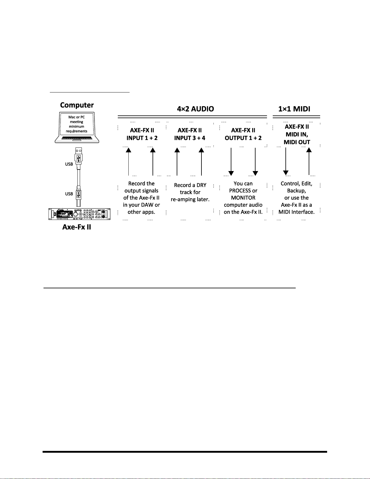
The USB 2.0 class-compliant driver provides two channels of 48k/24-bit audio from the computer to the Axe-Fx II,
up to four channels from the Axe-Fx II to the computer, and two-way MIDI-over-USB. All features can be used
simultaneously. Note that even though the Axe-Fx II is fully class-compliant, you must still install the drivers found
at http://fractalaudio.com/support .
Figure 2-4 – USB Features
Audio and MIDI ports (shown in the top dotted-outline boxes above) have different names on different systems. In
many applications, you can also assign “friendly names” to audio and MIDI ports.
Two Simultaneous Channels of 48k/24-bit Audio from the Computer to the Axe-Fx II
Two output channels allow audio to be sent from the computer to the Axe-Fx II where it can be processed by the
unit or simply played back to OUTPUT 1.
To process computer audio with the onboard effects, set the MAIN INPUT SELECT (p. 148) to “USB.” Computer
audio will be routed to the grid INPUT. This allows you to re-amp a dry track, for example, or use the Axe-Fx II to
process other audio or plugin tracks. It is possible to simultaneously record the processed output on the computer
using the Axe-Fx II audio inputs (0/1).
To pass unprocessed computer audio through the Axe-Fx II, set the MAIN INPUT SELECT (p. 148) to “ANALOG
(IN1)” (the default setting) or “SPDIF/AES.” Computer audio is mixed with the regular output of the Axe-Fx,
allowing you to play along with backing tracks or use the Axe-Fx II as a high quality “soundcard.”
Doc Q7.0 13
Page 26
OVERVIEW
Four Simultaneous Channels of 48k/24-bit Audio from the Axe-Fx II to the Computer
Four outputs, typically numbered 1–4, allow audio to be routed from the Axe-Fx II to the computer and recorded,
processed, or monitored.
USB/DIGI OUT SOURCE in the I/O:AUDIO menu (p. 148) determines what is sent to the first pair of USB outputs:
Selecting OUTPUT 1 L+R sends the Axe-Fx II main output to the computer. The same signal is, of
course, still routed normally to the rear XLR and unbalanced jacks. Use this to record your fullyprocessed guitar.
Selecting OUTPUT 2 L+R routes output 2—typically the FX loop block (p. 70) —to the first two outs.
Selecting MAIN INPUT routes the main input (see MAIN INPUT SELECT p. 148) to the first two outs.
A similar result can be obtained by using OUTPUT 1 with a “shunts-only” preset (p. 29).
Remember to turn off the Input Noise Gate and set Output levels to 0.0
Switching INPUT 1 LEFT SELECT (p. 148) to “REAR” allows you to record the line level outputs of a
microphone preamp, keyboard, or any other sound source via the rear INPUT 1 L/R jacks.
The second pair of USB Outputs always outputs the raw, dry, unprocessed signal from the main input (i.e. the front
jack or the rear jack, depending on both what is selected under INPUT 1 LEFT SELECT (p.
148)) and the rear jack). These require USB 2.0 support (see Minimum Requirements above).
Warning: As with all input/output systems, certain routing configurations can result in audio feedback loops. Please exercise
care not to route active outputs to active inputs, or damage could occur to connected amps, speakers, or your hearing.
Two-way High-Speed MIDI Communication
MIDI-over-USB enables the Axe-Fx II and the computer to communicate back and forth. You can edit, perform
updates, send program changes from a sequencer, synchronize the tempo, automate sound changes, and more.
MIDI-over-USB is considerably faster than “legacy” MIDI, and allows two-way communication with the computer
over a single cable.
Fractal-Bot 2.3.4
Fractal-Bot, available from http://www.fractalaudio.com/fractal-bot.php is a
powerful, lightweight MIDI Utility for the Axe-Fx II. Use Fractal-Bot for firmware
updates, backing up your Axe-Fx, restoring backups, managing User Cabs, and more.
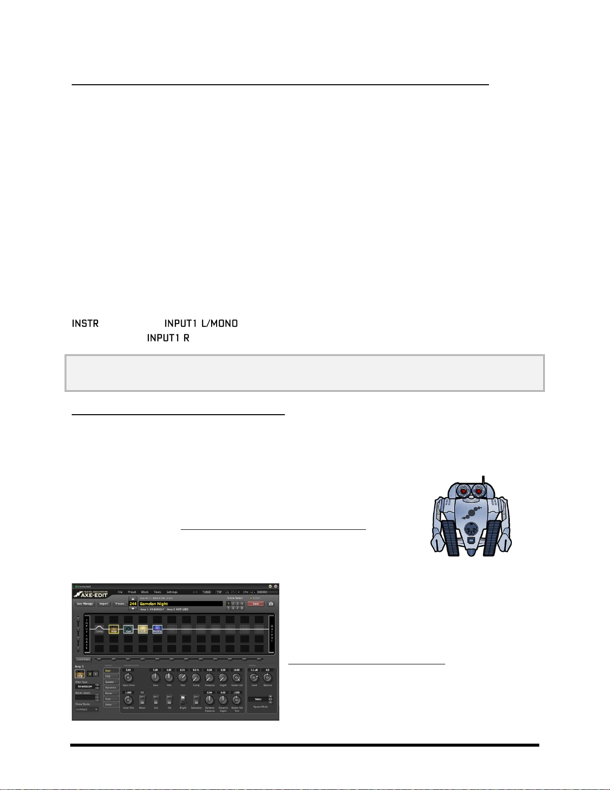
Axe-Edit 2.3.5
Axe-Edit is a full-featured software editor for the Axe-Fx II. It
provides a large, easy-to-use graphical interface that allows
you to create and edit sounds. Learn more at
http://www.fractalaudio.com/axe-edit
14 Doc Q7.0
Page 27
CONNECTIONS
3 Connections
Before making connections, be sure to turn down the volume of your amps and switch off all power. Take
extreme care NEVER to connect the SPEAKER outputs of an amplifier to any jack on the Axe-Fx II as this will
damage one or both devices. If you’re not sure, don’t do it!
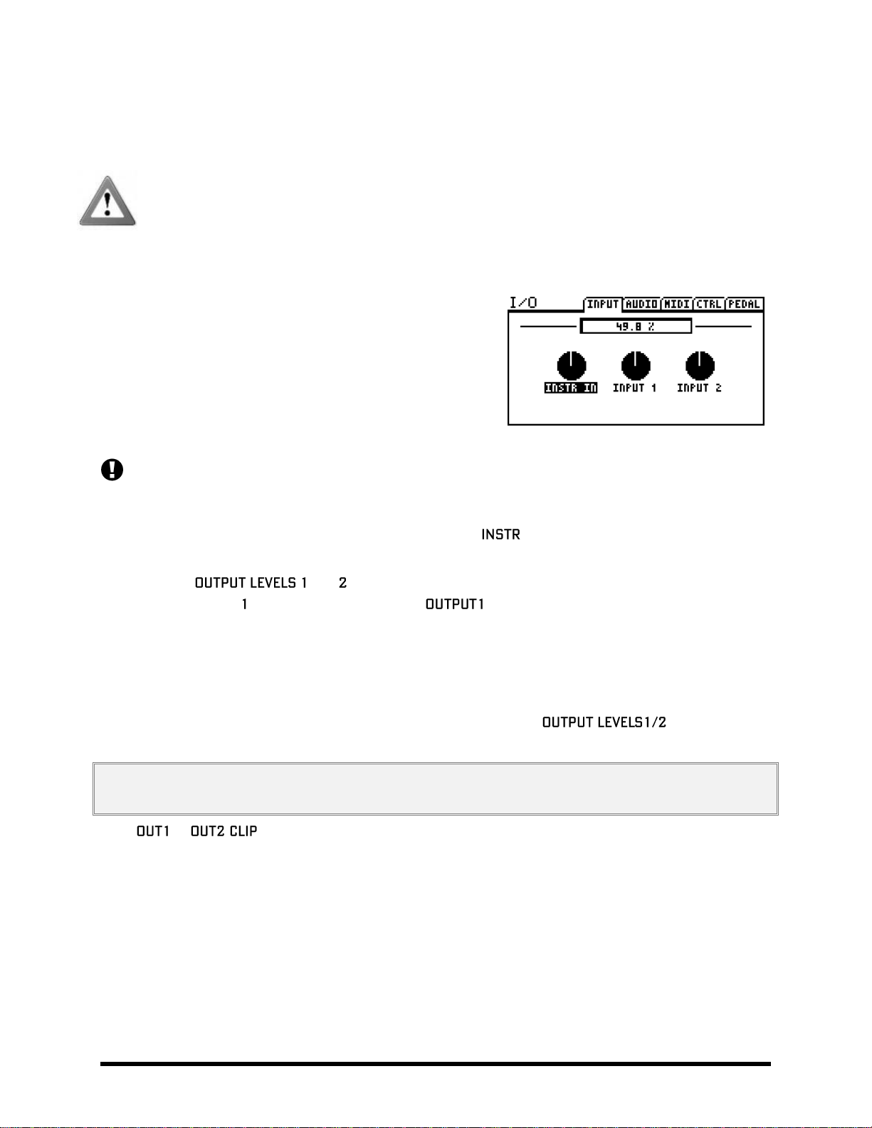
Setting Levels 3.1
For the Axe-Fx II to work properly, it is important that input and
output levels be configured correctly.
INPUT LEVELS are set with “soft-knobs” on the INPUT page of the
I/O menu. Adjust according to the level of input source material
until “hot” signals “tickle” the red LEDs on the front panel INPUT
meters. The red LED lights at -6 dB (below clipping). Some sources
may not reach ideal levels but can still be used with no problems.
Changing input levels will NOT affect what you hear. Inputs are compensated, meaning that as you lower trims
to optimize signal-to-noise ratio going into the converters, the output of the converters is adjusted inversely
so “what you hear” (and what reaches the signal processor) always remains the same.
Each input has its own dedicated analog-to-digital converter. The input jack parallels the rear inputs for
improved signal-to-noise performance.
The front panel and knobs independently control the volumes at the corresponding rear
panel jacks. The output knob simultaneously controls XLR and ¼-inch jacks, and the unit’s headphone
jack level. Optimal levels will depend on what the Axe-Fx II is connected to.
To operate with unity gain, set the Output Level knobs to maximum. If you then route shunts from the input to the
output you will get out exactly what you put in. (If you’re not using the Axe-Fx in the loop of a tube amp, unity gain
is likely not relevant.)
If levels result in clipping of attached equipment, turn down the front panel knobs. At the
minimum setting, volume is reduced but may not be silent.
NOTE: The Axe-Fx II uses digital potentiometers to adjust the output levels. These actually contain hundreds of tiny resistors
and switches. As such, some noise may be generated while adjusting the knobs.
If the or LEDS light while you use the Axe-Fx II, the problem is not trim settings but levels in the
digital domain. Chances are that the effects in your preset—many of which can increase gain significantly—are
simply too hot. Reduce the output of one or more blocks (the AMP block OUTPUT LEVEL is usually a good starting
point) or adjust the main GAIN slider of the preset’s output mixer (see p. 128).
When you need to adjust the level of all of your presets at once because some are clipping, you can also use the
GAIN slider on the OUT1 or OUT2 graphic equalizers to make a global adjustment. (p. 146)
Clipping can also be caused if you have increased the BOOST/PAD setting for one of the converters and can be
reduced if you adjust this setting to be closer to 0 dB (see p. 148). Block or preset adjustment may still be required.
Doc Q7.0 15
Page 28

CONNECTIONS
The PEDAL Jack(s) 3.2
Note: the Axe-Fx II XL+ and XL have two onboard jacks. The Axe-Fx II original and Mark II models have one.
Connect an expression pedal or footswitch to the pedal jack to control sound functions. You must first configure
the TYPE, and perform a simple calibration routine when using an expression pedal. See section 9.5 on p.154 for
how to use the PEDAL page of the I/O menu.
Any type of external switch can be used, as long as its contacts make and break the connection between tip and
sleeve on a regular 1/4” guitar cable. Expression pedals should have a linear resistance taper and max resistance
between 10kΩ and 100kΩ, and must be used with Tip-Ring-Sleeve cables.
To control sound parameters, you must first assign the PEDAL jack to an “EXTERNAL CONTROLLER” and then set up
a “MODIFIER.” This topic is covered in section 7: Modifiers & Controllers on p. 136, with a section specifically
about External Controllers on p. 144.
System Parameters 3.3
As you will discover, the Axe-Fx II has a range of flexible input/output options. The hardware descriptions cover the
basics, but seeing a few complete setups can also be helpful as you decide how to connect other equipment. The
following section illustrates some typical setups, some of which require specific “System Parameter” settings. For
example, when using a real, physical guitar cab, the global “Speaker Simulation” switch should be set to “OFF.”
In addition to the short introductions provided with the diagrams below, system parameters are detailed in section
8: Global Parameters, and section 9: Input/Output Parameters.
Many of the basic setups shown in the following pages can be easily combined or expanded. Make a mono setup
stereo. Add an MFC-101 MIDI Foot controller for intelligent remote control. Connect a computer to run Axe-Edit,
our free software editor. Combine multiple Axe-Fx II units into a single rig. Countless combinations are possible,
and creativity and experimentation can be as valuable here as when you are creating tones or dialing in effects.
16 Doc Q7.0
Page 29
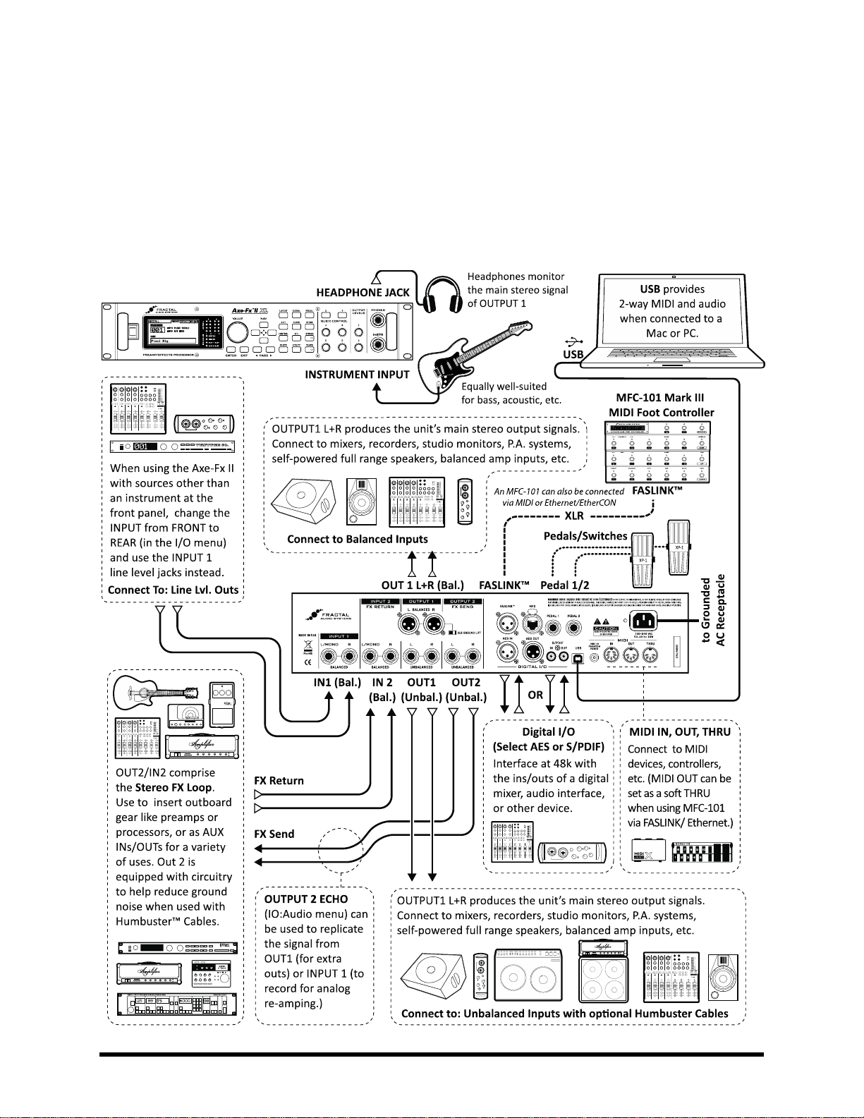
CONNECTIONS
Connection Diagrams 3.4
This overview will help familiarize you with the various inputs, outputs, and control connections of the Axe-Fx II.
The diagrams that follow in sections 3.4.1 through 3.4.10 illustrate several real-world applications.
Note that the Axe-Fx II Mark II has a shared MIDI OUT/THRU, and that MIDI THRU must be enabled in the I/O:MIDI
menu. The Mark II also does not have a FASLINK™ port, so an MFC-101 would be connected via MIDI,
Ethernet/EtherCON or a FASLINK™ adapter.
Figure 3-1 – I/O Overview
Doc Q7.0 17
Page 30
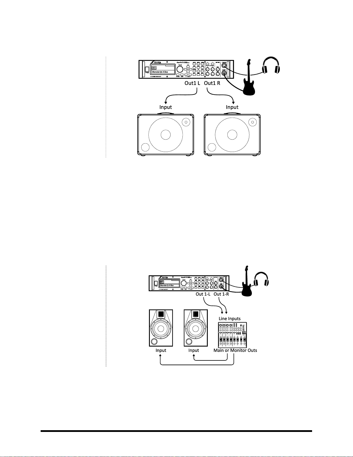
CONNECTIONS
COMPONENTS:
Guitar
Axe-Fx II
Self-Powered Full Range
Speaker(s)
Headphones (opt.)
Global Settings: Default I/O Settings: Default
Notes: With its built-in amp and speaker simulations, the Axe-Fx II can be played directly into P.A. or other self-
amplified, full-range, flat-response (FRFR) speakers. Externally amplified (passive) FRFR speakers are equally wellsuited. This might just as easily be a Front-of-House system with floor or in-ear monitors. In this configuration, the
Axe-Fx II creates all aspects of the end-to-end guitar chain for the ultimate in tonal flexibility—stompboxes, amps,
cabs, post effects, and more. Optional headphones provide an alternate way to listen when cabs are not present or
are switched off. Balanced (XLR) or unbalanced (1/4”) jacks and cables can be used to connect the Axe-Fx II, with the
former providing the advantage that less noise will be picked up over longer cable runs. If only one speaker is used,
set OUT 1 MODE in the I/O menu (p.148) to one of the mono options.
COMPONENTS:
Guitar
Axe-Fx II
Mixer (opt.)
Studio Monitors
Headphones (opt.)
Global Settings: Default I/O Settings: Default
Notes: This is essentially identical to the diagram shown above for Self-Powered FRFR speakers. The point to take
away here is that any system intended for full-range monitoring or sound reinforcement—from small computer
speakers to the P.A. at a huge arena—represents a suitable counterpart to the capabilities of the Axe-Fx II.
Axe-Fx II into Self-Powered Full-Range Speakers
3.4.1
Axe-Fx II into Studio Monitors 3.4.2
18 Doc Q7.0
Page 31

CONNECTIONS
COMPONENTS:
Guitar
Axe-Fx II
Power Amp and
Guitar Speakers
-OR-
Amp Head/Combo
with FX RETURN jack
(power amp input)
and Guitar Speakers
`
Global Settings: Power Amp Simulation ON or OFF (see below), Speaker Cabinet Simulation OFF
I/O Settings: Set OUT1 MODE (p.148) as required for stereo or mono.
Notes: Depending on the character of the amplifier being used, Power Amp Simulations may need to be ON or OFF
for this type configuration.
Power Amp simulations should be turned ON when using a “neutral-sounding” (Solid State) power amp that
does NOT significantly affect the tone or feel.
Power Amp simulations should be turned OFF when using the RETURN on a tube head or combo, or a guitar-
oriented tube power amp—one that significantly affects to the tone and feel.
In either case, it is completely safe and reasonable to try both settings to see which you prefer.
Whenever you use the Axe-Fx II with traditional guitar speaker cabinets (whether open back or closed, small or
large, alone or in pairs) it is best to turn Speaker simulations OFF in the CONFIG page of the GLOBAL menu (p. 145).
Guitar speakers differ from full-range speakers in that they are voiced to focus on traditional electric guitar sounds:
mids tend to be prominent, highs rolled off, etc.
The settings required for this type of operation are not ideally suited for monitoring through the Axe-Fx II
headphone jack, as what you hear through headphones will not sound like what you will hear through the speakers.
Switching Power Amp and Speaker Sims on and off, however, is simple and can be done as needed to switch back
and forth.
Axe-Fx II with Power Amp and Guitar Speakers 3.4.3
Doc Q7.0 19
Page 32

CONNECTIONS
COMPONENTS:
Guitar
Axe-Fx II, connected as
desired to
monitors/mixers/amps/
etc. (see other diagrams
for setup ideas)
Outboard Processor or
Preamp
Global Settings: See Below I/O Settings: See Below
Notes: The Axe-Fx II has a stereo FX Loop that allows you to insert outboard gear such as preamps or processors at
almost any point in the signal chain of any preset. You’ll learn more about editing presets in section 4, and the
Effects Loop block is detailed on page 70. For now, just be aware that custom presets are required for the Effects
Loop to be used. The Effects Loop configuration above is compatible with other setups that do not utilize INPUT2 or
OUTPUT2 for other purposes. Global and I/O options should be set accordingly.
COMPONENTS:
Guitar
Axe-Fx II
Mixer, recorder,
computer, etc. with
digital (S/PDIF or
AES/EBU) inputs and/or
outputs
Global Settings: Default I/O Settings: See below.
Notes: The digital connector jacks on the Axe-Fx II allow it to interface with a variety of devices with S/PDIF or
AES/EBU I/O. You can connect to the inputs of a digital mixer, for example, or process the signal from another unit
with a digital output, avoiding an unnecessary D/A:A/D round trip. The required clock rate for both input and output
signals is 48kHz. The Axe-Fx must be the master clock. “SLAVE” your 3rd party device by setting its clock source to
AES or S/PDIF. The onboard digital outs can monitor OUTPUT1, OUTPUT2, or the main INPUT, as specified in
USB/DIGI OUT SOURCE on the AUDIO page of the I/O menu (p. 148). The MAIN INPUT SOURCE must be set to
“SPDIF/AES” for digital inputs to be connected to the grid. A valid signal must be present at the selected digital input
or the Axe-Fx II will display “NO INPUT CLOCK!”
Axe-Fx II Effects Loop
3.4.4
Axe-Fx II Digital Audio Interconnection 3.4.5
20 Doc Q7.0
Page 33

CONNECTIONS
COMPONENTS:
Guitar
Axe-Fx II
Guitar Amp with a series
effects loop1 and built-in
or separate Guitar
Speaker(s).
Second Amp for Stereo
(opt.)
Global Settings: Defaults OK, since typical 4CM presets will not have AMP or CAB blocks!
I/O Settings: Set INPUT and OUTPUT MODES as required for stereo or mono (Remember: even in a stereo rig, when
you are connecting a guitar to the front INSTRUMENT input of the Axe-Fx II, INPUT 1 MODE must be set to “LEFT”.)
Adjust the two OUTPUT BOOST PAD parameters to lower the noise floor. See p.148 for details on these parameters.
Notes: This highly integrated setup places the Axe-Fx II simultaneously “in front of” an amplifier’s preamp section,
where it replaces traditional stompboxes, and in its effects loop, where “post” effects like delay and reverb have a
totally different sound than when used “out front”. (Although a head and separate cab are shown, many combo
amps also offer an onboard effects loop and can be used as well.)
To use the 4CM, you will need to create special presets where AMP and CAB blocks are replaced by the FX LOOP
block (p. 70). Signal hits the Axe-Fx II first, into any effects that you want in front of the amp—compressor, drive,
wah, and the like. Then, the FX LOOP block is used to “insert” the preamp of the actual amplifier on the grid. Output
2 of the Axe-Fx II has an all-new, extremely low-noise design that is well suited for feeding the front of an amplifier.
The signal makes a “round trip” to the amp’s preamp and back to the grid, where it is then processed by additional
blocks—your post FX: maybe chorus, delay, reverb, etc. The final routing is via Axe-Fx II OUT1/L to the Return
(Power Amp Input) of the amplifier which powers your speaker. To extend this configuration for optional stereo,
connect OUT1/R to the RETURN of a second amplifier, bypassing that unit’s preamp altogether.
The new Boost/Pad functions are designed to help run the OUT1 and OUT 2 D/A converters at optimum levels,
padding their outputs for even lower noise. To find the right setting, adjust either of these controls upwards until
you light the respective OUT CLIP LED on the front panel, then back off a few dB to prevent further clipping. You’ll
actually hear the noise floor drop as you make these adjustments.
Humbuster™ technology (p. 178), featured on all 1/4" outputs of the Axe-Fx II, can also provide a significant
reduction of ground hum when simple stereo-to-mono cables are used to connect to an amp or other device.
The no-amp/no-cab presets required for this setup are not well suited for headphone monitoring, as what you hear
in the headphones will not include any power amp or speaker simulations.
1
Axe-Fx II Four Cable Method (“4CM”)
3.4.6
Note: If your amp’s effects loop is the PARALLEL type, the chain of post-FX-loop blocks must be set to output a wet-only signal.
Doc Q7.0 21
Page 34

CONNECTIONS
COMPONENTS:
Guitar
Axe-Fx II
Guitar Amp
with Guitar Speaker
Front-of-House P.A.
Global Settings: Default I/O Settings: Set OUT1 MODE and OUT 2 MODE as required for stereo or mono
Notes: This setup is similar to others in which the Axe-Fx II is used direct into full-range speakers. Here, however, a
special preset feeds both the direct and power amp/cab rig by placing an FX LOOP block between the AMP and CAB,
so signal is passed to Output 2 before it is processed by the CAB block and passed to Output 1.
Note: A template is provided in preset memory location 381: “OUT1->FOH OUT2->CAB”
Another possibility is to use a preset with two totally separate signal paths. In the example below, the top (direct)
signal path contains a fully simulated guitar chain, while the second (backline) does not use a CAB sim.
The backline chain differs from the direct chain in several key ways. First, its AMP block has the “SAG” parameter set
to “0.00” to disable power amp simulation in that block only. Since real guitar speakers and a power amp are being
used at Output 2, no CAB block is inserted. Duplicates of effects following the amp are placed. This is useful because
different settings may be required to “sweeten” each system. The backline chain ends in an FX LOOP block, which is
routed via OUTPUT 2 to a power amp. If a very “neutral” amp is used, the SAG of that second AMP block might be
set higher for simulated tube power amp tone and dynamics.
Direct to FOH plus Real Amps on Stage
3.4.7
22 Doc Q7.0
Figure 3-2 – A Dual Chain Preset
Page 35

CONNECTIONS
COMPONENTS:
Guitar
Axe-Fx II
Guitar Amplifier with
built-in or separate
speaker cabinet
Global Settings: Defaults OK, since special presets required should not have AMP or CAB blocks!
I/O Settings: Change INPUT 1 LEFT SELECT to “REAR” if using the Axe-Fx II in an effects loop as shown above, left.
Leave the default setting of “FRONT” if you are connecting a guitar to the Axe-Fx II, as shown above, right.
Notes: Although it was designed for complete guitar signal path simulation, the Axe-Fx II can also be put to superb
use as a standalone FX processor. As such, it can be placed between guitar and amp to replace stompboxes or in an
amp’s effects loop where a rack processor would normally appear.
To use either setup, you will need to create custom presets without AMP or CAB blocks. For operation inside an
amp’s effects loop, use the REAR input(s) and set INPUT 1 LEFT SELECT (section 9.2) accordingly. Presets in this case
will likely contain only those effects that sound best after a preamp: chorus, EQs, delays, reverbs, certain types of
pitch shift and modulation, et al.
For the best-case scenario when running in front of an amp, recognize that Output 2 of the Axe-Fx II has an all-new,
extremely low-noise design that is well suited for this purpose. Effects-only presets should terminate in an FX LOOP
block to route signal to OUTPUT2. (In this case, nothing would be connected to the FX RETURN of the Axe-Fx II.)
The new Boost/Pad functions are designed to help run the OUT1 and OUT 2 D/A converters at optimum levels,
padding their outputs for even lower noise. To find the right setting, adjust either of these controls upwards until
you light the respective OUT CLIP LED on the front panel, then back off a few dB to prevent further clipping. You’ll
actually hear the noise floor drop as you make this adjustment. Humbuster™ technology (p. 178), featured on all
1/4" outputs of the Axe-Fx II, can also significantly reduce ground hum when simple stereo-to-mono cables are used
to connect to an amp or other device.
It is easy enough to extend each of the above configurations for use in stereo. With the Axe-Fx II in a loop, connect
OUT1 R to the RETURN of a second amp, bypassing that unit’s preamp altogether, or run fully within the loops of
two separate amps using IN1 L/R and OUT1 L/R. With the Axe-Fx II between guitar and amp, connect a second
amplifier to OUT2 R. The no-amp/no-cab presets required for the scenarios in this section are not well suited for
headphone monitoring.
Axe-Fx II as Effects Processor Only (with Guitar Amps)
3.4.8
Doc Q7.0 23
Page 36

CONNECTIONS
COMPONENTS:
Guitar
Axe-Fx II
Computer meeting
minimum requirements
(p. 12)
Powered Monitors
Headphones (opt.)
Global Settings: Default I/O Settings: See below
Notes: The Axe-Fx II offers great features when connected via USB to a computer. Pair this system with
headphones, studio monitors, or any other full-range listening system.
Simultaneously record stereo processed guitar and dry tracks for reamping.
2
Route stereo audio from the computer through the Axe-Fx II while simultaneously processing your guitar
so you can play along with tracks.
Send audio from the computer to the Axe-Fx II for processing (and send it back to record the result).
Use the Axe-Fx II rear inputs to record other line-level audio sources, with or without Axe-Fx II processing.
Use two-way, high-speed MIDI over USB for control/automation or Axe-Edit, the companion Editor
Librarian for the Axe-Fx II.
See section 2.3 for full details on USB audio and MIDI capabilities.
The Axe-Fx II can also be used in conjunction with any 3rd-party audio/MIDI interfaces.
2
Axe-Fx II as a Computer Audio Interface
3.4.9
USB 2.0 required for more than two simultaneous channels from the Axe-Fx II to the computer.
24 Doc Q7.0
Page 37

CONNECTIONS
COMPONENTS:
Guitar
Axe-Fx II
XLR Cable (for
FASLINK™)
MFC-101 Mk III
MIDI Foot Controller
Global Settings: Determined by how the Axe-Fx II is to be used with other connected amps/speakers/etc.
I/O Settings: Determined by how the Axe-Fx II is to be used with other connected amps/speakers/etc.
Notes: The Axe-Fx II XL/XL+ provides a significant advantage over its predecessors in that it can be connected
directly to the Fractal Audio MFC-101 Mark III MIDI foot controller via FASLINK™. FASLINK™ offers several
advantages over traditional MIDI or Ethernet/EtherCON connections. A standard XLR cable—easy-to-find and built
to withstand abuse on stage—carries bidirectional communications to support an MFC-101 running in “Axe-Fx
Mode,” with automatic preset name and tuner display on the floor, “smart” tri-state Instant Access Switch LED
support, TotalSync (where changes made at the Axe-Fx also happen on the MFC) and more.
When FASLINK™ is used, the MFC-101 still transmits/receives standard MIDI data to/from the Axe-Fx II XL/XL+,
which can then forward messages to other devices (Note: The MIDI THRU port is hardwired to MIDI IN… You must
instead use the MIDI OUT port and enable MFC ECHO TO MIDI OUT in the MIDI page of the I/O menu of the XL. This
is not required on a Mark II, but you must ENABLE MIDI THRU in the same menu on that unit.)
Though the XL and Mk III are shown above, you can in fact use any Axe-Fx II with any MFC-101. For a complete list of
connectivity options, please see the MFC-101 Quickstart Guide, available on the support page of fractalaudio.com.
High-quality XLR, Ethernet and EtherCON cables can be found at http://www.fractalaudio.com/cables
WARNING: Do not connect the MFC-101 power adapter to the MFC-101 or to the Phantom Power jack
of the Axe-Fx II while using FASLINK™ or an Ethernet/EtherCON cable. The Axe-Fx II provides required
power to the MFC from its internal power supply.
Always ensure that the Axe-Fx II is powered OFF before connecting or disconnecting the MFC-101.
3.4.10
Axe-Fx II XL/XL+ and MFC-101 Mark III
Doc Q7.0 25
Page 38

CONNECTIONS
3.4.11
Axe-Fx II XL/XL+ & MFC-101 Mark III: One Possible “Big Rig”
Here the Axe-Fx II XL/XL+ is the centerpiece of a “big rig,” combining the capabilities of several other diagrams
shown above. The main outs feed a pair of powered FRFR cabs, so you can design and monitor sounds through the
speakers you’ll perform with. Meanwhile, USB provides all of the usual computer audio and MIDI integration
features, with full-range studio monitors connected to a 3rd-party audio interface for monitoring and playback.
We’ve added an outboard processor in the FX LOOP (so you can clone its settings and put it on eBay ;)
*Note that MIDI OUT is used for MIDI THRU on the XL when an MFC-101 is connected via FASLINK™ or EtherCON.
Enable MFC ECHO TO MIDI OUT (In I/O:MIDI). On an earlier Axe-Fx II, the MIDI OUT/THRU would be used.
26 Doc Q7.0
Page 39

BASIC OPERATION AND EDITING
4 Basic Operation and Editing
Once you have set up your Axe-Fx II with speakers/amps/monitors or a pair of headphones, you can begin to
audition the factory preset sounds and learn to make changes by following this detailed guide to basic operation.
For a super-condensed version, see the 60-Second Edit Guide on p. 172 of the Appendix.
Presets 4.1
Each factory preset is a complete “end-to-end” guitar sound with amps, cabs, and effects—perfectly mixed and
ready to perform. In the sections that follow, you’ll learn to view, edit, and create presets from scratch. To begin,
let’s look at the ways to load the presets stored in the Axe-Fx II.
Presets are accessed from the PRESET page of the RECALL menu. There are 4 ways to change the preset:
1. The knob selects Presets sequentially.
2. The UP/DOWN buttons change by +/- 1
3. The LEFT/RIGHT buttons change by +/- 10
4. Turn the to “DIR” for a directory of all
presets by number. The “A-Z” page lists all presets by
name. Use the wheel to navigate and press
to load the selected preset.
The Axe-Fx II Mark II has 384 presets. The XL has 768.
Presets can also be loaded using MIDI program change commands
from external devices, such as an MFC-101 or 3rd party MIDI Interface.
Although it isn’t indicated in the display, presets are organized into
banks. Bank A contains presets 0–127, B contains 128–255, and C
contains 256–383. On the Axe-Fx II XL/XL+, presets 384– 511 are in
Bank D, presets 512–640 are in Bank E, and presets 641–768 are in Bank F. (See p. 192 for a cross-reference on
CC#0 bank/program changes and preset numbers.)
An onscreen message will be displayed in the main RECALL screen for any preset containing one or more links to
Global Blocks (p. 131).
Each Axe-Fx II preset also contains eight SCENES. The current Scene is shown on the recall screen and can be
changed with the “A” QUICK CONTROL knob. For more on setting up SCENES, see p. 184.
Doc Q7.0 27
Page 40

BASIC OPERATION AND EDITING
The Grid 4.2
The grid, located on the EDIT page of the LAYOUT
menu, is a 12 × 4 “matrix” where effect “blocks”
are inserted and connected to build presets. The INPUT
appears at the left, the OUTPUT at the right. The display can fit a 5 × 4 section of the 12 × 4 grid at any one time,
with the ability to scroll to off-screen areas using the buttons. A bottom scrollbar indicates where you are in
the overall left-to-right layout.
Figure 4-1 – In this image of an empty grid, off-screen areas are grayed.
Inserting and Removing Blocks 4.2.1
As explained in “The Concept” on page 6, the Axe-Fx II grid must be populated with blocks—components pulled
from a large inventory of amps, cabs, stompbox, studio effects, mixers, and more. The insertion, modification, or
removal of blocks happens at the grid cursor, a filled rectangle controlled with the buttons.
Figure 4-2 – Grid Operations
To INSERT a BLOCK into an empty space…
Use the buttons to select the desired empty grid location.
Turn the wheel. Available block names (AMP 1, CAB 1, etc.) will be displayed on the screen in
alphabetical order, and the selected block (if visible) will flash.
When the desired item is found, press to insert it into the grid. To cancel, press instead.
As detailed above in The Inventory/Grid Concept (p. 6), every preset draws from its own complete inventory of
available blocks. As you place them on to the grid, they are removed from the inventory.
28 Doc Q7.0
Page 41

BASIC OPERATION AND EDITING
The total number of blocks you can insert in any one preset is dictated by the fact that CPU utilization must not
exceed around 94%. Each block has a “cost,” and when the sum of all blocks reaches the limit, a warning message
prevents you from adding additional blocks. The Axe-Fx II is extremely powerful, and most presets do not come
close to the limit. See Understanding Preset Size Limits on p. 173 for more on this subject.
To CHANGE the type of an existing BLOCK…
Use the buttons to select the desired block.
Turn the wheel. Available block names (AMP 1, CAB 1, etc.) will be displayed on the screen in
alphabetical order, and the selected block (if visible) will flash.
The Axe-Fx II offers multiple instances of most block types (ex: 2 Amps, 4 Graphic Equalizers, etc.)
To keep the list manageable, only the “next-in-line” instance is shown as you cycle through the
insertion menu, so AMP 2 is hidden until you have placed AMP 1.
When the desired block is shown, press . To cancel without making changes, press
instead.
To REMOVE an existing BLOCK…
Use the buttons to select the block you wish to remove.
Turn the wheel until NONE is displayed and press , or press to cancel.
Shortcut! To remove any block except a Shunt, select it and press
Shunts 4.2.2
A shunt is a passive connector—a utility block that carries signal through otherwise empty grid locations. Shunts
are required because, although you may only wish to have a few components in your chain, signal does NOT flow
through an Axe-Fx II preset unless you completely connect the INPUT to the OUTPUT. A single Axe-Fx II preset can
contain up to 36 shunts.
Figure 4-3 – Shunts are used to span distances between INPUT, BLOCKS, and OUTPUT.
In the figure above, a shunt connects the Input to the WAH, and five shunts connect the Delay [DLY] to the Output.
Empty grid locations are indicated by dotted outlines and the absence of a three-letter abbreviation or thru-line.
Doc Q7.0 29
Page 42

BASIC OPERATION AND EDITING
To INSERT a SHUNT into an empty grid location…
Use the buttons to select the desired empty grid location.
Turn the wheel once to the right. “SHUNT” will be displayed in a popup, and the selected grid
space will flash if not hidden.
Press . To cancel without inserting, press instead.
To CHANGE any other block type into a SHUNT…
Select the desired block.
Press . “SHUNT” will be displayed in a popup, and the selected space will flash if not hidden.
Press . To cancel without inserting, press instead.
Connector Cables 4.2.3
As mentioned above, a preset’s INPUT must be connected to its OUTPUT in order for that output to produce any
sound. Blocks (including shunts) create the components of a chain, but these still need to be connected to one
another for signal to “flow.” This is done using routing connectors, commonly referred to as “cables.”
Figure 4-4 – Two otherwise identical presets shown WITH and WITHOUT connector cables between the blocks.
The second example above would produce NO SOUND as nothing is “wired up” to pass signal to the output!
If a preset is unexpectedly silent, inspect it carefully for one or more missing cables.
A key concept to understand is that every connector/cable is stereo. The grid allows 4 full stereo paths, and
most blocks are stereo in/stereo out. Even blocks which process audio in mono (like AMP or DRIVE output in stereo
and have a left-right BALANCE control. The Effects Guide (p. 39) covers the mono/stereo capabilities of each block
type in detail. For now, remember that every connector/cable is stereo in and of itself.
30 Doc Q7.0
Page 43

BASIC OPERATION AND EDITING
The Rules of Axe-Fx II Cables
No cables = No sound. Even one missing link will break the entire chain.
Signal always flows from LEFT to RIGHT.
A cable MUST originate from a BLOCK or a SHUNT. Empty locations are not viable origins.
If you try to connect to an EMPTY location, a SHUNT will be created there.
You can ONLY connect to blocks in the next column to the right.
The represents the origin of a connector cable.
The shows valid possible destinations.
The symbol shows destinations that are illegal/unavailable.
Any columns farther left or right would also be illegal/unavailable.
If the were in a different ROW, every would still be in the same place.
Cables are created AUTOMATICALLY between the INPUT and any blocks in the first column.
Cables are created AUTOMATICALLY between the OUTPUT and any blocks in the last column.
You may freely SPLIT or MERGE the signal up to four ways at any point. This is sonically transparent
and there is zero risk of inherent phase or other problems in the split/merge itself. CROSSING is also
possible.
Figure 4-5 – Cables can CROSS one another without issue. Routings can be as COMPLEX as required.
To Create a Connector Cable…
Use the buttons to select the block where you wish the cable to BEGIN.
You can’t start from an EMPTY grid space!
The first and last grid columns are automatically connected to the INPUT and the OUTPUT.
Press . The selected block and its neighbor to the right will alternately flash as “selected.”
Use the UP or DOWN buttons to select the desired destination block.
Remember that you will be prevented from trying to select blocks in other columns.
It is possible to select an empty location, but a shunt will be added automatically at the
destination if you complete the cable.
Be sure to select a destination that is not already connected to the origin block, or you will
REMOVE that cable (see below).
Press . To cancel without connecting, press instead.
To Remove a Cable Connector…
Cables are removed in much the same way as they are created.
Select the block where the cable begins.
Press . The selected block and its neighbor to the right will alternately flash as “selected.”
Doc Q7.0 31
Page 44

BASIC OPERATION AND EDITING
Use the UP or DOWN buttons to select the “other end” of the cable you wish to remove.
Press ENTER. To cancel without removing, press EXIT instead.
A Shortcut for Spanning Empty Spaces
This shortcut allows you to span multiple empty grid columns with a series of automatic shunts and cables. This
technique is especially useful when you have placed your last effect block and need to wire it to the output or if
you want to fill an empty row with shunts.
Select any block that is followed by a series of empty spaces.
PRESS and HOLD the button. The intervening spaces will be automatically filled with shunts
and connected with cables.
You can also use this shortcut for small “runs” to connect any blocks with one or more columns of empty space
between them, but be careful: any existing cables encountered along the way will be REMOVED by the process!
A Word on Shunts and Cables
In the real world, cables and connectors can have an impact on the tone of a guitar rig. In the Axe-Fx II, nothing
could be further from the truth. Shunts and connectors, whether long, short, split, merged, or crisscrossed in a
huge mess, have absolutely no sonic properties whatsoever. They do not impart color, add latency, suck tone,
create load, invite hum, develop shorts, or get tangled up in the road case. A word of advice: merging identical
copies of a split signal will result in additive level increase and should be avoided in favor of simply increasing one
or another gain or level parameters. And remember… both shunts and cables are stereo!
Moving Blocks on the Grid 4.2.4
The menu also includes a MOVE page with tools to move individual blocks or entire rows or columns UP,
DOWN, LEFT, or RIGHT. When a block or a grid row/column is moved, it changes places with the item in the space
it is moved to. This can result in certain connector cables being modified or removed, so be sure to observe how
the elements of your preset are interconnected before proceeding with a MOVE operation.
Press .
Use the buttons to select the MOVE tab.
Select a function with the wheel:
EFFECT LEFT/RIGHT/UP/DOWN
COLUMN LEFT/RIGHT
ROW UP/DOWN
Use the buttons to select the target effect block or row/column you wish to move. Look for the
SOLID square(s) in the grid representation on the screen.
Press to execute the move.
Repeat this step to move the same target again in the same direction.
32 Doc Q7.0
Page 45

BASIC OPERATION AND EDITING
Example Presets on the Grid
4.2.5
Four sample presets are shown below as visualized in Axe-Edit, the companion software editor to the Axe-Fx II.
Review the diagrams to get a sense of how presets are constructed and how they appear on the grid.
EXAMPLE 1: Simple Amp Tone – In this extremely simple preset, an AMP and a CAB are combined for a straightahead tone. Shunts and connectors (which appear in Axe-Edit almost as one continuous cable), connect the INPUT
to the AMP, the AMP to the CAB, and the CAB to the OUTPUT.
Figure 4-6 – Amp/Cab Preset
EXAMPLE 2: Long Pedal Chain – Here, effects are strung together to create a giant virtual rig. Compressor, Volume,
Wah, Whammy, Tremolo, Overdrive, Phaser, and Flanger are all connected to an AMP/CAB combination, followed
by Delay and Reverb. As you can see, the Axe-Fx II supports a great number of simultaneous effects; this preset
uses just a portion of the unit’s total CPU power, leaving considerable room for more effects on other rows.
Figure 4-7 – A Pedal Chain
Doc Q7.0 33
Page 46

BASIC OPERATION AND EDITING
EXAMPLE 3: Dual Amp Preset – This preset shows a dual-amp rig. A series of effects (Wahwah, Drive, Phaser)
begins the chain, then the signal is split into two amps and two cabs. Signal is panned hard left and right with CAB
block BALANCE controls and then merged to feed stereo post effects. A Multiband Compressor helps balance
dynamics, while spaces in the chain leave plenty of room for future expansion.
Figure 4-8 – Dual Amp Preset
EXAMPLE 4: Complex Routing – The program below demonstrates a more intricate routing scenario. The signal is
split and merged at various points between the input and the output, with various effects appearing before and
after two independent amps. Notice the complex feedback-loop routing in parallel with the “dry” signal feeding
the amps, and the reverb at the end of the chain running in parallel. (Reverb level is controlled by an envelope for
a “ducking” effect).
Figure 4-9 – Complex Preset
MORE EXAMPLES…
The presets in this section represent only four examples of the nearly limitless possibilities that can be created
using the GRID, BLOCKS, and CONNECTORS of the Axe-Fx II. In addition to reviewing these diagrams, you can gain
valuable insight and ideas by exploring the factory presets or by discussing techniques with other members of the
Fractal Audio community. Visit forum.fractalaudio.com and join the discussion.
You can download additional presets for your Fractal Audio products at http://axechange.fractalaudio.com
34 Doc Q7.0
Page 47

BASIC OPERATION AND EDITING
Figure 4-10: Press EDIT with any block selected on the Grid
Editing Sounds 4.3
The blocks of the Axe-Fx II represent diverse types of real-world equipment. In the same way that such hardware
devices are equipped with different controls, blocks also typically have many adjustable settings called
parameters. Parameter settings determine precisely how an effect will sound. These are arranged on PAGES in the
display of the Axe-Fx II. The system of parameters and pages for any block is referred to as its EDIT menu.
To Open the EDIT Menu for Any Effect Block…
With a preset loaded in normal mode…
Press to display the GRID.
If the GRID is not shown at first, press to reach the EDIT tab.
Use the buttons to select the desired
block.
Press to display the EDIT menu.
buttons select parameters on the page.
The name of the selected parameter will be
displayed in .inverse. with “VAL” shown above
if it is a knob, or “>” shown to its left in text
menu pages.
In scrolling menu pages, the sidebar has an
indicator to show relative position.
The wheel changes the selected parameter.
Changes can be auditioned in real-time by playing while you edit.
For effect blocks with multi-page menus, the buttons select between them.
Press to return to the grid, or press to go back to play mode.
Pressing repeatedly will step through the EDIT menus for all blocks in a preset, sparing you a return trip to
the grid. You can also press without entering the grid to go directly to editing a selected block in any preset.
Figure 4-11 – Three Typical EDIT menu pages.
The above figure shows three pages of typical EDIT menus (from the AMP block). Notice the tabbed labels near the
top: PG1, PG2, EQ, ADV, and MIX. Select between these using the buttons. The third example shows a
text-only menu. Some blocks, like the Graphic EQ (p. 78), Parametric EQ (p. 97), and others, have specialized
graphical displays designed to provide rich, intuitive editing experiences.
Doc Q7.0 35
Page 48

BASIC OPERATION AND EDITING
1
1
Quick Control
4.3.1
The functions of the , , and knobs depend on which Axe-Fx II menu
or function is selected.
In the main screen, the A knob selects SCENES. See section 16.15 on p. 184.
In every EDIT menu
parameters for easy editing of multiple controls without the keys. Mapping is
indicated by a small A, B, C or D above or to the left of on-screen parameters.
When editing Amp TYPE, A, B, and C are conveniently mapped to DRIVE, MASTER, and LEVEL.
While on the MANUAL page of the menu, A, B, C and D work as “Manual knob” modifier sources,
allowing control of assigned parameters. See p. 144.
While STORING a preset, A, B, C and D are used as shortcuts to enter text. See p. 38.
, A, B, C and D are dynamically mapped to four on-screen
X/Y Switching 4.4
One of the new features of the Axe-Fx II is X/Y switching, available on many different effect block types:
Axe-Fx II Mark II: Amp, Cab, Chorus, Delay, Drive, Flanger, Pitch Shifter, Phaser, Reverb, and Wahwah.
Axe-Fx II XL/XL+: All of the above, plus Compressor, Gate/Expander, Graphic EQ, PEQ, Trem/Pan, and Mixer.
Each instance of each of these blocks is equipped with two fully independent sets of parameters—“X” and “Y”—
making it possible to switch between two completely different sound settings using only one block. You can
change between X and Y instantly at the touch of a front panel button (while editing) or by using MIDI remote
control (during performance). When you save a preset, the current X/Y state of each X/Y block is saved as well, so
the preset loads with your choices already selected. The X/Y state of each X/Y block is also stored in every scene
(see Scenes on p.184).
The benefits of X/Y Switching are considerable. You might simulate amp channel switching (X as American Clean
and Y as British Crunch). This won’t require the CPU overhead of two separate amp blocks! Another application is
channel-switching effects. Instead of painstakingly tuning modifiers for morphing (p. 136), you can just dial in X,
dial in Y, and switch between them at will. Imagine a delay that can be switched at will from pristine dotted-eighthnote echoes with light feedback to one with saturated, modulated quarter-note echoes and heavy feedback.
X/Y switching is generally seamless, but the AMP block requires a moment to reload when you change XY.
It is important to understand that MODIFIERS (see p. 136) are SHARED between X and Y states.
To Use X-Y Switching
Open the desired block for editing.
All blocks default with the X state selected. Dial in all parameters for the X state.
Press and dial in all parameters for the Y state.
Save the preset (see p. 38).
Each available X/Y switch has its own dedicated global MIDI CC# assignment for remote switching2. This option is
found in the I/O:CONTROL menu. See p. 152 for details.
Exceptions: Quick control functions work in PEQ blocks, but letters are not shown. Mixer type blocks do not support Quick Control.
36 Doc Q7.0
Page 49

BASIC OPERATION AND EDITING
4
2
3
4
X-Y / Y-X Copying
You can copy all of the settings from X to Y, or Y to X, by double tapping the button for the one you want to copy
to, and then pressing to confirm. So, to copy X to Y, double-tap and then press . If you accidentally
double tap when you don’t want to copy, press to cancel.
X/Y Quick Jump 4.4.1
The X and Y buttons also double as user-definable Quick-Jump keys. These allow quick access to the EDIT menus of
your two favorite blocks from almost any screen without needing to “drill down” through the grid. You might, for
instance, set “X” to jump to AMP1, while “Y” might be assigned to bring up the PHASER1 menu.
Quick-Jump is disabled if you are already in the EDIT menu of another block (including Global Blocks or Modifier
sub menus), or if you are in the process of SAVING (where X and Y are used for quick character entry).
Quick Jump settings are assigned in the X/Y page of the I/O menu, detailed on p.
154.
Bypassing a Block 4.5
Can you imagine a stompbox that can’t be stomped? Neither can we.
Any effect3 on the Axe-Fx II can be bypassed (or engaged) in three different ways:
1. Press the front panel button while the block is either selected in the grid or open to edit.
Note that accidentally double tapping or holding FX BYP will enter the Global Blocks menu instead
(see p. 131). Press and try again if this happens.
2. Use a MODIFIER (section 7) attached to the block’s BYPASS MODE parameter.
3. By remote control via the block’s global remote bypass function, which may be set to “PEDAL” or to any
MIDI CC# on the CTRL page of the I/O menu (p. 148.)
A bypassed block is shown on the grid with a dotted outline.
When you bypass any block, one of several things can actually happen depending on how its BYPASS MODE
parameter is set. For more on this, see the section on Common Mix Parameters beginning on p.128.
Every SCENE stores the bypass state for every block in a preset. See section 16.15 on p. 184.
Loading Effects from another Preset 4.6
The Recall Effect function makes it possible to load block settings directly from one preset to another. To perform
this operation, select the EFFECT tab of the RECALL menu using the buttons. Select the preset and block that
you want to load from and press . “EFFECT RETRIEVED!” will be displayed, and the “local” block (whether or
not it is already on the grid in the current preset) will be updated with all settings from the “retrieved” block. All
settings for both X and Y are recalled for those effects that support X/Y. Modifiers (p. 136) are also recalled. If the
block you are trying to load is not found in the preset you try to load it from, “EFFECT NOT FOUND” will be shown
instead. Note that you can also recall NOISE GATE, MAIN OUT, and CONTROLLER (LFO1, LFO2, etc.) settings.
As noted in the section which covers I/O parameters, X is in fact the “ON” state for these CC switches (64-127) and Y is the OFF (0-63).
The MIXER, FB SEND, and SHUNT blocks have no bypass functions.
The ENHANCER has no BYPASS MODE parameter.
Doc Q7.0 37
Page 50

BASIC OPERATION AND EDITING
Saving Changes 4.7
After making various changes, you will undoubtedly want to save the results of your edits.
To store a sound in place, without changing its name or location…
Press to show the STORE screen.
Press to initiate the process, and again to confirm.
The message “STORED!” is displayed when the operation completes.
To store a sound to a new location or with a new name…
The Axe-Fx II has hundreds of numbered preset memory locations. It is possible at any time to save any preset into
any location. It is also possible to change the NAME of a preset before you store it.
Press to show the STORE screen.
Use the buttons to select between the two available functions:
The LOCATION parameter selects where the preset will be stored:
The wheel selects numbered memory locations. left/right skip by 10.
Navigating down to the NAME parameter allows you to edit preset names before saving:
Turn the wheel to select from all available characters.
The “ ” knob selects UPPER CASE letters.
The “ ” knob selects LOWER CASE letters.
The “ ” knob selects NUMBERS.
left/right or the “ ” knob will move the cursor position.
The “ ” button inserts a character at the cursor position.
The “ ” button deletes a character at the cursor position.
You can use up to 23 characters in a preset name.
Press to Store, then press again to Confirm.
The message “STORED!” is displayed when the operation completes.
Swapping the Locations of Two Presets 4.7.1
The Axe-Fx II has a new feature that allows you to SWAP the locations of two saved presets. This is useful, for
instance, if you want to re-order without overwriting factory presets, or if you need to move a “keeper” preset to a
different location so you can overwrite its previous location with a newer entry. To SWAP two presets:
Press and to the right to the SWAP page.
Use keys and the wheel to select the two presets whose locations you want to switch.
Press to Store.
Press to Confirm. The message “SWAPPED!” will briefly appear when the operation
completes.
38 Doc Q7.0
Page 51

EFFECTS GUIDE
5 Effects Guide
The Axe-Fx II offers 34 different basic block types that can be combined freely up to the limit of available DSP
resources to create your own presets. An alphabetical listing of block types follows.
Amplifier [AMP] 5.1
The Amp block reproduces the sounds of an impressive array of vintage and modern guitar and bass amplifiers,
with 256+ different “types” based on stock, custom, and hybrid models. It uses our newest Quantum Amp
Modeling technology, including proprietary multi-stage nonlinearity generators to create ultra-realistic distortions.
Separate virtual preamp and power amplifier stages create rich, cascaded drive tones that cannot be obtained
using simpler modeling methods.
You can achieve great tone using only the basic amp controls on the first page or two. Should you desire to dig
deeper, you’ll find many exciting parameters that allow you to tweak and adjust the deepest aspects of your amp’s
sound. These are detailed below. Axe-Edit also makes using the amp block easier, with a few simple pages
organized with common parameters grouped together.
Note: The Cab block (p. 50) is vital in creating an overall sound. If you’re not getting the tones you’re
expecting from an amp, try different cab settings!
The heart of the Quantum™ Amp block is its capacity for ultra-realistic distortions, created using our proprietary
multi-stage non-linearity generators, with virtual preamp and power amp stages emulating the different types of
distortion generated by a tube preamps and power amps. The models also offers accurate behavior for the drive
and tone stack controls over the full range of operation. This means you can set onscreen controls to match those
of the original amps to dial in familiar settings and generally achieve expected results.
Each Axe-Fx II preset can use two fully independent Amp blocks. Presets that use a single amp block run in high
resolution, providing the utmost in fidelity and resistance to aliasing. This mode is automatic and is selected
whenever there is only one amp block in the layout grid. Adding a second amp block will revert both to normal
resolution (in which the modeling is still of extremely high quality.) Note that switching between high and normal
resolution presets there can be an additional switching latency as amp blocks need to be soft-reset.
Figure 5-1 – A simplified diagram of the AMP block. The AMP block processes audio in mono.
INPUT SELECT and BALANCE parameters allow flexibility when combining the AMP with stereo effects.
The Amp block supports X/Y Switching. See p. 36 for more information.
Amp Type 5.1.1
Amp types are presented in an alphabetical list. A complete table appears on p. 165. You can adjust DRIVE, MASTER,
and LEVEL parameters directly from the TYPE page by using the A, B, and C knobs.
Doc Q7.0 39
Page 52

EFFECTS GUIDE
Amp Preamp Page (“PRE”)
5.1.2
INPUT DRIVE – (aka “Drive”) sets the amount of preamp gain/distortion. Used in conjunction with the
MASTER (see below), INPUT DRIVE determines whether the sound will be clean, slightly broken up,
moderately overdriven, or completely distorted.
Our modeling faithfully reproduces the sound of the treble peaker circuit on the INPUT DRIVE control found on
many amps. This can be heard as the low frequencies are reduced more than the highs when the INPUT DRIVE
is turned down (and vice versa).
For amps that have no MASTER VOLUME, the INPUT DRIVE also functions as the amp’s VOLUME control.
NOTE: Amp models that simulate “jumpering” the inputs of a 4-hole amplifier (e.g. PLEXI 50W JUMP, HIPOWER JUMPED, etc.)
have separate TREBLE DRIVE and NORMAL DRIVE controls, which behave as Controls for their respective channels.
OVERDRIVE – The OVERDRIVE control appears only for certain amp types. Note that DRIVE and OVERDRIVE
are applied to the appropriate points in the circuit for the amp being modeled, i.e. prior to the last triode
stage or prior to the third triode.
INPUT TRIM – Amps without OVERDRIVE will display the INPUT TRIM instead. This allows you to adjust for
more or less preamp gain than the actual circuit being modeled. This is different than the Input DRIVE control
because DRIVE interacts with the surrounding circuitry, changing frequency response as it is varied.
BOOST – Toggles an additional 12 dB of gain at the input of the amp sim. (For amp types that have an
OVERDRIVE control (see above,) BOOST appears only on the ADVANCED page.)
BASS, MID, TREBLE – While other modelers use simple filters to approximate amp tone controls, the Axe-
Fx II replicates exactly the frequency and phase response of a classic passive tonestack. In most instances,
matching knob settings between the Axe-Fx and the original amp will recreate the same tones.
Some of the original amps simulated on the Axe-Fx II do not have all of the tone controls offered on our
models. Some, for example, have no mid control. To faithfully simulate the configuration of the original, set
any superfluous controls to noon (or “0.00” if you are using the “ACTIVE” tonestack type; see below). Of
course, you may still adjust to achieve tones the original amp does not have.
Extreme tone and high gain settings can cause pickup squealing or excessive noise. This is especially true
with the TONESTACK TYPE (p. 54) set to “ACTIVE.”
CUT SWITCH – (engaged by a switch beneath BASS) reduces the amount of low frequencies into the amp
simulation. This can be used to achieve a “tighter” tone or to reduce low-end “flub”.
FAT SWITCH– In the same way the TREBLE knob (above) also controls BRIGHT, the MID operates as a “Fat”
switch, emphasizing midrange “body” by shifting the tonestack center frequency down.
BRIGHT SWITCH – Many amplifiers contain a “treble peaker,” included as a pull or toggle switch, or even
hard-wired. Every amp TYPE on the Axe-Fx II includes this control (even if the original mode does not). The
effect may be subtle or quite pronounced depending on the amp TYPE. This is also affected by the BRIGHT CAP
setting (p.54). If the original amp had no bright circuit, BRIGHT is OFF by default but can still be turned on to
40 Doc Q7.0
Page 53

EFFECTS GUIDE
BRIGHT switch ON
BRIGHT switch OFF
apply circuit values suited to an amp of that general type. If the amp has a hard-wired treble peaker, the
default BRIGHT state is ON.
To turn the Bright, Fat, or Cut switches ON or OFF, use the keys to select the knob above them and
press . The label beneath the knob will fill to indicate that the circuit is engaged.
BRIGHT (knob) – This is a high treble filter between the preamp and power amp, useful to darken or
brighten the tone in a unique way. This control accurately replicates the “Presence” control on the original
version of the “USA Pre” type amps. (Not to be confused with the “BRIGHT SWITCH” (see below) which
engages/disengages a capacitor across the drive pot.
Amp Power Amp Page (“PWR”) 5.1.3
PRESENCE/HI-CUT – The Presence control boosts (or cuts) the upper frequencies from the power amp
simulator by varying the negative feedback frequency response. Increased presence can help a sound cut
through a heavy mix.
Amps with no negative feedback circuits in their design cannot utilize a presence circuit. Therefore, for amp
types of this type (or for any type if you manually set NEGATIVE FDBK to 0.00) the PRESENCE control is
replaced with the “HI-CUT” control. This high-frequency filter allows you to control the tone the power amp.
When changing to a model with no negative feedback (i.e. Class-A, Mr.Z, Recto Red), be sure to check your
presence settings as settings higher than zero may darken the sound undesirably.
When certain “USA” amp models are used, a PRESENCE SHIFT switch appears beneath the Presence knob. This
replicates the behavior when the Presence knob is pulled out on these amps. Note that the behavior of this
switch is authentic and may result in volume reduction when active since the negative feedback is increased
which lowers the loop gain.
DEPTH – Boosts low frequencies from the power amp simulation by varying the negative feedback frequency
response. The DEPTH control is set by default to an appropriate value when the amp TYPE is selected, but this
setting may be overridden.
TUBE TYPE – The virtual power amp in the Axe-Fx includes modeling of the plate impedance of the power
tubes. Plate characteristics are adjustable via DYNAMIC DAMPING, an advanced parameter. The TUBE TYPE
parameter sets DYNAMIC DAMPING automatically for you, allowing you to select from common power tube
types instead of selecting a number. EL34, EL84, 6L6, 6V6, KT66, KT88, 6550, 6973, 6AQ5 and 300B (triode) are
offered, as well as an ideal tetrode and ideal pentode. The power tube type defaults to the appropriate type
when the amp type is selected but may be changed freely.
Doc Q7.0 41
Page 54

EFFECTS GUIDE
NEG FDBK – This controls the amount of negative feedback, or damping, in the power amp simulation.
Higher values give a tighter and brighter sound but can sound harsh at very high master volume levels. Lower
values give a loose and gritty sound and feel. Like many other power amp parameters, NEGATIVE FEEDBACK is
set to an appropriate value whenever you change the amp TYPE, but it can then be changed as desired. For
example, you might dial in some negative feedback on a “Top Boost” to give the power amp a more
“American” sound while still retaining the preamp voicing.
MASTER VOLUME – The almighty Master Volume! This is a very important control. It determines the
distortion and dynamics characteristics of the power amp simulator, and its setting is central to an amp’s
sound. As the Master is turned up, the tone controls will have less influence, and the sound will have more
“bloom” and touch sensitivity. Settings for MASTER don’t necessarily correspond to knob positions on the amp
being modeled. With a little experimentation on your favorite Axe-Fx II amps, you will learn to appreciate the
different DRIVE and MASTER VOLUME settings and how to enjoy different combinations.
When you select an amp TYPE, the MASTER will change to an appropriate/typical setting for that amp. If a
real amp doesn’t have a Master, the “correct” setting for MASTER VOLUME is 10.0.
At high Master settings, less drive is usually required, especially for high-gain types.
Amps designed for preamp distortion will typically sound great with the MASTER VOLUME set low to
prevent the tone becoming muddy or noisy. This includes the USA Lead types, SOLO 100, and others.
Amps with negative feedback (damping greater than zero) tend to have a “crunchier” power amp
distortion, which can get “raspy” if driven too hard. You can experiment with the interactivity of DAMPING
(see Advanced Parameters, below) and MASTER VOLUME to achieve desired distortion timbres.
Setting SAG (see below) to zero will disable Power Amp simulation, at which point the MASTER becomes a
simple level control with 40 dB of range.
If more power amp gain is desired, the MASTER VOLUME TRIM parameter (See section 5.1.7) can be used
for increased range.
OUTPUT LEVEL – This is a copy of the LEVEL control on the MIX page for easy volume adjustment without
page turning. This only affects volume. It has no effect on tone! For many people, this is the “go to” parameter
for setting the output level of a preset.
Amp Speaker Page (“SPKR”) 5.1.4
These parameters shape the virtual speaker impedance curve and the resulting resonances in the virtual power
amp. Amp/Speaker interaction elicits an increase in power amplifier response at certain frequencies, affecting the
tone. Note that the power amp frequency response will not equal the speaker impedance if the NEGATIVE FDBK is
greater than “0” (because negative feedback flattens the response curve).
LOW FREQ, LOW Q, LOW RES – Guitar loudspeakers have a low-frequency resonance, typically about
100 Hz. This shifts up slightly when the speaker is mounted in an enclosure.
HI FREQ, HI RES – A loudspeaker voice-coil presents an inductive load to the power amp at high
frequencies. This inductive load, in conjunction with the output transformer capacitance, creates a highfrequency resonance at the specified frequency.
XFRMR LF, XFRMR HF – These set the output transformer bandwidth.
42 Doc Q7.0
Page 55

EFFECTS GUIDE
SLOPE – This parameter allows fine adjustment of the high-frequency impedance of the virtual voice coil
(which affects the slope of the impedance curve). A speaker voice coil is “semi-inductive” due to eddy current
losses in the motor. This presents an impedance to the power amp that is neither fully inductive nor fully
resistive. The amount of resistive loss varies by brand and type. Reducing the Slope simulates a speaker that is
less inductive, increasing Slope simulates a speaker that is more inductive. Typical speakers range from 3.0 to
4.5 with the median being about 3.7. Lower values yield greater midrange while higher values are more
scooped and sizzly.
SPEAKER DRIVE –This parameter simulates distortion caused by pushing a speaker too hard. It interacts
with the MASTER, which determines how hard the actual power amp is pushing.
XFRMR DRIVE – Controls how hard the virtual output transformer is driven. Higher values simulate a
smaller, more easily saturated transformer.
Amp EQ Page
The amp block includes a built-in graphic equalizer, eliminating the need to use a separate block for tone-shaping.
You can change the number of bands to a variety of types. Press to reset all EQ bands to flat.
TIP: You can also change the Amp EQ type with the UP and DOWN nav buttons.
See the Graphic Equalizer [GEQ] block on (p.79) for additional detail on bands, Q, etc., but remember that the GEQ
in the amp block is limited to a maximum of eight bands.
Power Amp Dynamics Page (“PWR DYN”) 5.1.5
SUPPLY SAG – This controls power amp dynamics. Higher settings simulate higher power supply impedance,
and thus greater tube plate voltage “droop,” for a more compressed feel. This control interacts with the
Master and will have little effect if the power amp is not being pushed. As the power amp is pushed and draws
more virtual current from its virtual power supply, the SAG control will have more effect. (Note this same
parameter appears in the ADVANCED menu as MAINS IMPEDANCE (SAG).
IMPORTANT: Turning SUPPLY SAG fully counterclockwise defeats power amp simulation for an individual
AMP block, allowing it to be used into an external (real) tube power amp without globally disabling power
amp simulation. (See section 8.1 on p. 145 or the “FOH + Real Amps” diagram on p. 22 for more.) In this mode,
MASTER works as a simple volume, DEPTH is deactivated, and PRESENCE turns into a simple shelving filter.
B+ TIME CONSTANT (in the Advanced menu) interacts with the Sag control because it makes the power
supply response slower or faster. When the supply is fast it will sag rapidly accentuating the pick attack and
compressing after. Most guitar players like this, but setting it too fast will cause excessive AC ripple and ghost
notes. For convenience the virtual power supply voltage (B+) is shown as a meter on this page when the
SUPPLY SAG control is selected. The meter displays the supply voltage in dB, relative to the idle voltage.
TUBE BIAS – (This is the same parameter as the PWR TUBE BIAS control on the Advanced page). This sets the
controls the quiescent operating current of the virtual power tubes. This powerful parameter allows you to
fine-tune power amp distortion characteristics to your particular style. The higher the value, the less
crossover distortion. When bias is reduced the amp sags and bounces more, with tighter bass and edgier tone.
Doc Q7.0 43
Page 56

EFFECTS GUIDE
XFRMR MATCH – Transformer Match is an extremely powerful parameter that sets the relative output
transformer primary impedance to determine how easily the power tubes are driven into clipping. Higher
MASTER Volume settings result in a more pronounced effect. Increasing XFRMR MATCH causes power tubes to
clip sooner. Decreasing XFRMR MATCH causes power tubes to clip later and therefore the phase inverter and
grid clipping becomes more predominant. At higher settings, the resonance settings on the SPEAKER page of
the AMP block will be more pronounced. For optimum results bring up the MASTER until the desired amount
of power amp distortion is achieved, then adjust matching until the character of the distortion is as desired.
The various LF and HF resonance parameters interact strongly with this parameter so be sure to experiment
with those as well when crafting a tone.
XFRMR Grind – Transformer Grind accurately simulates the effects of dynamic core losses and leakage
inductance in the virtual transformer. Higher values result in more high frequency response and a more
“open” sound. Very high values can yield a raspy, spitty tone common in vintage and/or low wattage amps.
Modern “big iron” amps tend to have low values. Note that the amount of grind you will hear is dependent
upon how hard the virtual power amp is driven and is more noticeable as the MASTER is increased. In real
amps this effect is highly dependent on the speaker. Some speaker/transformer combinations exhibit
significant high frequency dynamic boost while other combinations yield almost none. As always use your ears
as the final determinant of the settings that will work best for you.
OUT COMP –The Output Compressor parameter controls the ratio of a compressor specifically tailored to
reduce the output dynamics of the Amp block. A bar graph beneath the knob shows gain reduction.
COMP TYPE – (Output Comp Type) - Sets the type of Output compression. The “Output” type compresses the
block’s output. The “Feedback” type also applies dynamics to the input of the block, so you will get more
distortion as you play harder and less when you play softer or roll back the volume.
The Output Compressor also uses OUT COMP THRESHOLD and OUT COMP CLARITY in the Advanced menu.
Amp Preamp Dynamics Page (“PRE DYN”) 5.1.6
PREAMP COMP (“Preamp Compression”) – Determines the amount of compression in the virtual cathode
follower. You can also set the attack time and ratio of this compressor (in the Advanced menu using the CF
TIME and CF RATIO parameters) or change its TYPE (below)
COMP TYPE (“Preamp Compression Type”) – Selects between “Authentic”, which accurately models the
compression in a tube amp, and “Ideal”, which is an idealized distorting compressor. The idealized type is
more focused and has tighter bass whereas the authentic type is bolder and looser. High gain players may
prefer the ideal type due to its tight character.
DYNAMICS – Sets the strength of an input dynamics processor that can be used to alter the response of the
amp. When set below zero the amp resulting in a smoother, less dynamic sound. When set greater
than zero the amp resulting in a punchier, crunchier and more dynamic sound. Note that extreme
values can have undesirable side-effects such as pumping and clipping.
CRUNCH – Adds crunch, as in Cap’n...
44 Doc Q7.0
Page 57

EFFECTS GUIDE
PREAMP BIAS – Sets the bias point of the last triode (not counting the cathode follower). Depending on the
bias points of the previous stages, increasing or decreasing this value can alter both harmonic content and
attack characteristics. Typically, if the previous stage has a bias then increasing this value will be
more noticeable (and vice-versa). This value is set automatically when amp TYPE is changed, but can be
altered any time as desired.
HARMONICS – Not the type you play with a soft touch, but the type that occur naturally inside an amp as
tubes interact. Higher values increase the interaction between virtual tubes, yielding “softer” distortion.
Amp Dynamic EQ Page (“DYNEQ”) 5.1.7
DYNAMIC PRESENCE – This models output transformer leakage inductance that results in a brightening of
the tone when the power amp is pushed. This control is set to a default value when the model is selected
corresponding to the real amp, if applicable. Increasing this value results in a brighter response as the virtual
power amp is pushed. When playing softly or at lower gains, the influence of this control is lessened. Note that
this only affects the power amp modeling and is dependent on the degree of power amp overdrive. This
control can also be set negative to cause the tone to darken when playing hard. This control can also be used
to help “dial in” the sweet spot of an amp model. As the MASTER is increased an amp becomes more liquid,
compressed and easier to play. However, the highs may get overly compressed, causing the amp to sound too
dark. The Dynamic Presence control allows you to get the desired power amp drive and liquid feeling and then
bring the highs back without affecting the rest of the spectrum.
DYNAMIC DEPTH – Analogous to the Dynamic Presence control, this increases low frequencies when the
virtual amp is being pushed. While real amps don’t display this behavior, it is a valuable tone-shaping tool .
CHARACTER TYPE, CHARACTER FREQ, CHARACTER Q, CHARACTER AMOUNT – These
parameters control a powerful “inverse homomorphic” filter which adjusts tone dynamically in a very musical
way. When playing softly these dynamic filters have little effect on the sound. As the amount of distortion
increases, the influence of these filters increases. CHARACTER FREQUENCY and Q set the center frequency
and width of the filter, while CHARACTER AMOUNT sets how pronounced the effect is.
This control is similar to DYNAMIC PRESENCE and DYNAMIC DEPTH but the frequency is adjustable. For
example, for a tone that darkens when you play harder, set CHARACTER FREQUENCY to 10000 Hz and the
CHARACTER AMOUNT to -5. For the reverse, set amount +5 and the tone will brighten when you play hard.
CHARACTER AMOUNT defaults to zero whenever a new amp TYPE is selected.
CHARACTER TYPE determines the type of filter type used, shelving, peaking or dynamic. The “Dynamic” type
can be used to fatten or scoop the tone as a function of picking strength. For example, set the TYPE to
Dynamic, CHARACTER FREQUENCY to 450.0, CHARACTER Q to 0.7 and CHARACTER AMOUNT to 4.0 for a tone
that gets fatter and thicker as you play hard but is not “honky” when you play soft.
Doc Q7.0 45
Page 58

EFFECTS GUIDE
Amp Advanced Page (“ADV”)
5.1.8
INPUT SELECT – The AMP block processes audio in mono. This control determines how incoming stereo
signals will be processed. You can input only LEFT or RIGHT channels, or SUM L+R (the default setting).
MODELING VERSION – (XL/XL+ ONLY!) Selects which version of Quantum modeling the currently
selected Amp block will use. (See also “Force Default Version” in the Global Config menu on p. 145.)
BOOST – Toggles an additional 12 dB of gain at the input of the amp block.
INPUT TRIM – Allows you to adjust the relative gain of the preamp. Increasing the value will cause the amp
to have (more or less) gain. It is simply a linear gain applied at the input to the block. You can use it to give a
typically clean amp a bit more oomph or decrease the gain of a very high-gain amp. Note that this is different
than the Input Drive control because the Drive control interacts with the surrounding circuitry and changes
the frequency response as it is varied.
MSTR VOL TRIM – Allows you to adjust the range of the MASTER. Increasing this value above 1.0 will cause
more gain in the virtual power amp, while values below 1.0 will result in less gain.
MSTR VOL CAP – (“Master Volume Capacitor”) sets the value of the bright cap across the Master Volume.
MSTR VOLUME LOCATION – (“Master Volume Location”) – Sets the location of the Master Volume. Most
amps have the Master Volume before the phase inverter (“Pre PI”). On some amps (like the “Class-A” types)
the Master Volume is after the phase inverter (“PI”). A third option, “pre-triode,” is the default for amp types
based on Hiwatt® models.
BRIGHT – This switches appears on the PRE page, but is offered here with a modifier option.
BRIGHT CAP – Sets the value of a virtual capacitor to determine the sonic effect of the BRIGHT switch
(above). Increasing this will make the preamp brighter and vice versa.
SAT SWITCH – The Saturation Switch engages a popular “mod” between the preamp and the tonestack for a
thicker, more aggressive distortion character. The “ON (AUTHENTIC)” and “ON (IDEAL)” settings differ only in
volume. “IDEAL” gives you the hotter output you wish a real amp had with saturation engaged ;-)
SAT DRIVE – Controls the amount of SAT SWITCH saturation. The default value differs for each model.
LOW-CUT FREQ – This control allows you to reduce the amount of low-frequency content at the input to
the amp simulator. This parameter defaults to a value for each type but can be overridden if desired.
HIGH-CUT FREQ – This control sets the cutoff frequency of a low-pass filter at the very end of the preamp
simulation. It defaults to a preset value for each amp type but can be overridden if desired. Experiment with
this to fine-tune your tone. For example, some of the higher-gain amp types are characterized by fairly heavy
filtering after the preamp stage. Increase or decrease for a brighter or darker tone.
DYNAMIC DAMPING – The Axe-Fx virtual power amp models the plate impedance of the power tubes.
They give tight bass and warm highs at higher MASTER settings, with “3-dimensional” tone. The plate
characteristics are adjustable via the Dynamic Damping parameter. The value of this control is changed
automatically when you set the TUBE TYPE parameter on the PWR page.
DEFINITION – This control is a basic “tilt EQ” which adds highs/cuts lows, or vice versa. It is located at the
amp input, so its effect is heard before preamp distortion or a front-end tone stack.
46 Doc Q7.0
Page 59

EFFECTS GUIDE
TONESTACK TYPE – The BASS, MID and TREBLE controls operate by default as “passive” controls. That is,
they simulate exactly the frequency and phase response of the classic passive tonestacks found in the original
amplifiers our simulations are based on. The TONESTACK TYPE control lets you change this behavior from
PASSIVE to ACTIVE, or to substitute the passive tonestack of another amp type.
Selecting the “ACTIVE” type gives each tone control +/- 12 dB boost/cut operation for up to twice the
range of a typical amplifier. Since the active tone controls are more sensitive, small adjustments have
bigger effects, and less extreme settings still achieve pretty extreme sounds. For example, full PASSIVE
treble for a high-gain British amp would be equivalent to only +5.0 dB ACTIVE, leaving 7 dB of additional
headroom! Active tone controls do not interact like those of a typical amplifier, so when you adjust the
treble, the mid and bass are not affected. This can make dialing in a certain tone easier and quicker than
it might be with a PASSIVE tonestack.
Selecting a substitute tonestack allows you to mix and match amps and tone stacks to create your own
hybrids. This allows you to use, for example, a Plexi-type tonestack on a Blackface amp model, or a
modern German tonestack in a British Preamp.
TONESTACK FREQ – Sets the center frequency of the tone controls to determine their effect on the sound.
This control works whether you are using ACTIVE, PASSIVE, or substitute tone stacks.
This parameter defaults to an appropriate value whenever you change the amp TYPE, but it can then be
changed as desired. However, if you subsequently change the TONESTACK TYPE, the TONESTACK FREQUENCY will
not necessarily be correct anymore.
TONESTACK LOCATION – This control lets you change the location of the tone stack. “PRE” places the
tone stack at the input to the preamp, “POST” places the stack between the preamp and power amp. “MID”
places it between the last two triode stages, and “END” places it after the power amp (which is physically
impossible with a real amp). Defaults to an appropriate value whenever you change the amp TYPE.
EQ TYPE – This determines the number of bands for the amp block’s built-in graphic equalizer (from 3 to 8)
and whether it will be variable Q, constant Q, passive or console type.
PRESENCE FREQ – This multiplier alters the center frequency of the amp’s PRESENCE control, which is
naturally determined based on the current selection for amp TYPE.
DEPTH FREQ – Alters the center frequency of the amp’s DEPTH and DYN DEPTH controls. This parameter
defaults to an appropriate value whenever you change the amp TYPE, but can then be changed as desired.
POWER AMP BIAS SHIFT – Controls the amount of phase inverter bias shift. Note that some real amps
are “spitty” in nature due to PI bias shifting, and the new algorithm is designed to replicate that behavior
accurately. If you find this undesirable reduce PI BIAS SHIFT as desired although this will reduce authenticity.
POWER AMP GRID BIAS – (aka “Power Tube Bias”) Sets the bias point of the virtual power amp. Lower
values approach pure Class-B operation. Higher values approach pure Class-A operation.
POWER AMP GRID BIAS – Sets the bias point of the virtual power amp. Lower values approach pure
Class-B operation. Higher values approach pure Class-A operation.
Doc Q7.0 47
Page 60

EFFECTS GUIDE
BIAS EXCURSION – The higher this value, the more the bias shifts when the virtual power tubes are
overdriven. Bias excursion pushes a power amp from Class-AB operation towards Class-B operation, which
can result in crossover distortion. A little goes a long way, but too much can lead to what is referred to as
“blocking distortion” which can make an amp sound unpleasant.
PA CATHODE RESONANCE – There are two types of power tube bias: fixed bias and cathode bias. In a
cathode biased amp a resistor is placed between the power tube cathode and ground thereby self-biasing the
tube. This parameter sets the value of the virtual cathode resistor. Higher values result in a more negative
bias and push operation towards Class-B, resulting in more crossover distortion.
POWER SUPPLY TYPE, AC LINE FREQUENCY – These select between AC and DC virtual power supply
types. AC rectification and resulting supply ripple are modeled, and the line frequency is also selectable. Note
that as with a real tube amp, the AC Supply can cause “ghost notes” when Sag is low and B+ Time Constant is
high. Lower B+ Time Constant values will make the amp feel “faster,” but too low can also cause ghost notes.
AC VOLTAGE (VARIAC) – This sets the relative AC line voltage into the amp simulation implementing a
virtual “Variac”. Note that normally the volume would vary with the Variac setting in a real amp but the
simulation compensates for this.
MAINS IMP. (SAG) – This is a duplicate of SUPPLY SAG on the amp’s PWR DYN page.
PREAMP SAG –Turning this ON replicates the behavior of an integrated tube head or combo amp as
described above. Turning this OFF replicates the preamp sag behavior of separate preamp and power amp.
NOTE: Preamp modeling uses screen voltage from “power amp in” calculations rather than operating
independently. This improves feel as preamp voltage drops with power amp sag. The effect is more noticeable
as SAG is increased. Note that preamp sag has a long time constant and, as such, the initial pick attack is
relatively unaffected while sustained sounds undergo compression. This results in a “chewier” sensation.
B+ TIME CONSTANT – Controls the rate of change in the power tube plate supply. Lower values give a
bouncier feel, while higher values give a tighter feel. TIP: Remember that you can also monitor B+ when supply
sag is selected on the Power Amp Dynamics page (“PWR DYN”).
TRIODE1 PLATE FREQ, TRIODE2 PLATE FREQ – These parameters set the cutoff frequency of the last
two triodes in the chain. Many amps have a capacitor across this triode’s plate resistor. This capacitor is used
to smooth the response and reduce noise. You can adjust the amount of capacitance, and the resulting
frequency, using these parameters.
CATHODE SQUISH, SQUISH TIME – The Axe-Fx II has “cathode squish modeling” for cathode biased
power amp models. CATHODE SQUISH sets the amount of bias shift due to cathode voltage rise and SQUISH
TIME sets the time constant of the cathode network. These parameters are set to default values upon
selection of an amp TYPE. (Setting CATHODE SQUISH to zero defeats the cathode squish modeling.)
OUTPUT COMP, COMP THRESHLD – These control the output compressor (detailed previously on the
DYNAMICS page.) The THRESHOLD can only be set here, on the ADVANCED page.
BIAS EXCURSION — The Axe-Fx II accurately models grid conduction and resulting bias excursion. This
results in a more dynamic, thicker and bouncier tone. BIAS EXCURSION controls how much the grid voltage
droops when the grids conduct.
CF (PREAMP) COMP – a duplicate of the Preamp Comp parameter on the Preamp Dynamics page.
48 Doc Q7.0
Page 61

EFFECTS GUIDE
CF TIME, CF RATIO – These parameters determine the attack time and ratio used for CF (Preamp) Comp.
CF HARDNESS – The Quantum firmware series improved modeling for tubes driving cathode followers. In
models that use cathode followers, this results in warmer distortion with smoother decay. Set the shape of
cathode follower distortion using this parameter.
OUTPUT COMP THRESH – Sets the threshold of the Output Compressor (found on the Power Amp
Dynamics page (“PWR DYN”).
OUTPUT COMP CLARITY – Used in conjunction with the other Output Compressor parameters, this
adjusts the bass response of the compressor and can be used to add clarity to the bass.
PREAMP TUBE TYPE – This selects a tube type for the virtual preamp from the following options: 12AX7A
JJ, 12AX7A RCA, 12AX7A Syl(vania),12AX7A, 12AX7B, 7025, ECC83, ECC803S, EF86. This parameter is set
automatically to an appropriate type whenever a new amp model is selected.
PREAMP HARDNESS – Controls the asymmetry of the triode mode to determines how sharply they enter
saturation, simulating “softer” or “harder” tubes. This subtle effect is most apparent at edge of breakup.
Lower values give softer saturation with less even and more odd harmonics. Higher values give a more
aggressive breakup. The default is set when an amp Type is selected but can be changed any time.
PREAMP BIAS – This is a duplicate of the PREAMP BIAS parameter on the amp’s DYN PRE page.
POWER AMP HARDNESS – Controls the hardness of the virtual power tube grid clipping. The lower the
value the softer the distortion, but this often is not noticeable because negative feedback around the power
amp makes the distortion harder. Another factor which controls power amp hardness is Transformer Match:
turn it up, and turn down Negative Feedback for softer power amp distortion.
POWER AMP BIAS – Adjusts the offset voltage of the virtual power amp to vary the symmetry of the
clipping of the virtual power amp. A value of zero produces nearly symmetrical clipping with very little even
harmonics. Higher values are increasingly asymmetrical which increases even harmonics. Small amounts of
even harmonics can make the power amp distortion sound “warmer” and more bell-like while higher amounts
will give a “fuzzier” tone. Most amps have some amount of offset and the amp models will default to a typical
value. Note that this parameter is only applicable for push-pull power amp types. For single-ended power
amps the Power Tube Bias parameter sets the symmetry (as always).
PICK ATTACK – Controls a sophisticated dynamic range processor that operates on leading edge transients.
Negative values reduce pick attack while positive values enhance it.
AMP Trem/Mix Page
The Amplifier block also has a MIX page with LEVEL, BALANCE, and BYPASS MODE parameters.
See Common Mix Parameters on p. 128 for more information.
TREM FREQ, TREM DEPTH – These create true bias tremolo by varying the bias of the virtual power
tubes. Bias Tremolo is very organic and varies based on a multitude of variables including power amp settings,
damping, bias, and more. It is also “self-ducking” and decreases as you play harder. On some amp types,
extreme bias TREM DEPTH can result in excessive crossover distortion. On other amps the amount of tremolo
can vary greatly between loud and soft playing. All this, however, is part of the allure of bias tremolo as it
results in a particularly “organic” sound.
Doc Q7.0 49
Page 62

EFFECTS GUIDE
Cabinet [CAB] 5.2
The Speaker Cabinet Simulator (“Cab” for short) recreates the tonal characteristics of any number of speaker
cabinet configurations. The Axe-Fx II XL/XL+ contains over 150 built-in “factory” cabinet simulations, plus 1024
memory locations for loading custom “User Cab” files. (The Mark II contains 130+ factory and 100 user cabs). The
Cab block also offers room and microphone simulations (including sub-millisecond delays), plus basic tone
controls.
Factory cabs include custom creations by Fractal Audio Systems, plus selections from 3rd-party libraries by Mikko
Logrén of ML Soundlab, Buddy Gill, RedWirez, OwnHammer, TheAmpFactory, and contributions from Fractal
Artists John Petrucci, James Santiago, and loudspeaker design engineer Jay Mitchell.
The cab block supports both standard (2048) resolution IRs, and newer UltraRes™ format IRs. UltraRes™ is a
proprietary format that enhances the resolution of an IR without added CPU burden or storage requirements.
Each Axe-Fx II preset can use two fully independent Cab blocks.
The Cab block supports X/Y Switching. See p. 36 for more information.
Cab Parameters
CAB (TYPE) – Sets the cabinet type by selecting from “FACTORY” and “USER” IRs. Cabinet types are listed in
the table in section on p.169. The four SCRATCHPAD locations found at the end of the list are designed to
allow you to “audition” cabs before committing them to a memory location. This capability is especially useful
when user cab memory is full, or when you are using Cab-Lab (available from http://shop.fractalaudio.com).
Please note that the contents of the SCRATCHPADs are cleared every time you restart the Axe-Fx.
MIC (TYPE) – Selects the microphone simulation type used. There are ten different types based on classic
guitar cabinet microphones.
Manufacturer and product names mentioned below are trademarks or registered trademarks of their respective owners,
which are in no way associated or affiliated with Fractal Audio Systems. The names are used only to illustrate sonic and
performance characteristics of the Axe-Fx II MIC TYPES.
57 DYN (based on the Shure® SM57®)
58 DYN (based on the Shure® SM58®)
421 DYN (based on the Sennheiser MD 421 II®)
87A COND (based on the Shure® Beta 87A®)
U87 COND (based on the Neumann® U87®)
E609 DYN (based on the Sennheiser® e609® Silver)
RE16 DYN (based on the Electro-Voice® RE16®)
R121 COND (based on the Royer Labs® R-121®)
D112 DYN (based on the AKG® D112®)
67 COND (based on the Neumann® U67®)
“NULL” is a perfectly transparent mic with a PROXIMITY control (below.)
“INVERT” is perfectly transparent and enables PROXIMITY, but also phase inverts the signal.
“NONE” disables microphone processing in the CAB block.
PROXIMITY – Simulates the classic proximity effect, causing an increase in bass or low frequency response
as proximity is increased. The PROXIMITY control has no effect when MIC TYPE is set to “NONE.”
DELAY – This short delay (0.000-1.000 ms) provides the ability to simulate microphone distance as employed
to create interesting phase or comb filter effects. You’ll need to have two parallel cabs with different delay
settings to hear this. Furthermore, the effect is most pronounced when the cabs are summed to mono.
50 Doc Q7.0
Page 63

EFFECTS GUIDE
Figure 5-4 Two Amp Blocks into a STEREO Cab
SPKR SIZE – This control “scales” the IR to simulate shrinking or enlarging the virtual speaker. This effect can
be used to shift where the tone “sits” in a mix, or to create dramatic effects. Subtle settings (0.9-1.1) will
sound most natural. SPKR SIZE is not offered in STEREO modes or when the selected IR is running in UltraRes.
INPUT SELECT – For use in the MONO cab modes. This determines how incoming stereo signals will be
processed. Options include inputting only LEFT or RIGHT channels, STEREO or SUM L+R. This can be used, for
example, to run two Cab blocks in parallel for stereo processing by setting one to Left and the other to Right.
MODE – Offers “HI-/ULTRA-RES,” “STEREO ULTRA-RES” “NORMAL RES” and “STEREO” (normal res) modes.
Fractal Audio Systems Cab IRs come in two different formats: Standard Res, and UltraRes™. UltraRes IRs use a
patent-pending proprietary technology to deliver enhanced sonic resolution without high latency or CPU load.
When you use UltraRes™ IRs and set the Cab block mode to UltraRes, the highest quality sound is achieved. If
you don’t use Ultra-Res data, the IRs will load in “high” resolution.
Selecting one of the “Normal” options causes all IRs (even UltraRes™ IRs!) to load in standard resolution,
without the benefits of UltraRes™.
“STEREO” modes offer two Ultra-Res or two Standard Res impulses to be loaded in a single cab block. Fully
independent left and right side parameters appear when you select this option.
Figure 5-2 –HI-/ULTRA-RES and NORMAL RES modes.
Figure 5-3 –STEREO and STEREO ULTRA-RES modes
To use a stereo Cab block with two amps, connect both amps to the cab. Then
set the BALANCE control for one Amp fully left, the BALANCE for the second amp
block fully right, and set the Cab block MODE to “STEREO.”
See Stereo Cab Mode Parameters (below) for more.
Doc Q7.0 51
Page 64

EFFECTS GUIDE
DEPHASE – This parameter controls a sophisticated process that removes the “phasiness” from IRs and can
yield a more “amp in the room” experience.
LOW-CUT/HI-CUT/FILTER SLOPE – Adjusts the cutoff points of high-pass and low-pass filters. Increase
the low-cut to reduce bass boom. Decrease the high-cut to darken the tone. Slope allows you to select
between first-order (6 dB/octave) or second-order (12 dB/octave) filters.
ROOM LEVEL, ROOM SIZE – These controls determine the level and virtual size of a room reverb
simulation that is built into the cab simulator block. Increase to add room ambience to the sound.
MIC SPACING – Increases delay times inside the room reverb simulation by simulating the distance of the
room microphone from the sound source.
PROXIMITY FREQ – This allows tuning the frequency range over which the proximity effect occurs.
STEREO LINK – Available only when the Cab MODE is set to “STEREO”, LINK turns the LEFT channel
parameters into master controls, which set identical values for LEFT and RIGHT parameters. You can still
override the right channel parameters values if desired.
Stereo Cab Mode Parameters
When the MODE of the CAB block is set to “STEREO”, independent instances of the following parameters appear
for left and right.
CAB (TYPE) L/R
MIC L/R
PROXIMITY L/R
LEVEL L/R
PAN L/R – Pan Parameters appear only when cab MODE is stereo.
DELAY L/R
SPKR SIZE is not offered when CAB MODE is set to “STEREO”.
Cab Preamp Simulation Parameters
A microphone on a guitar speaker is subject to the pleasing musical distortion generated by the mic preamp. This
might range from a subtle “warming up” to a full on “nasty-fying.” Preamps also offer their own tone controls
which change the sound of the mic’d speaker. The Cab block includes several controls to simulate these effects.
PREAMP MODE – (on “PG2”) offers “High Quality” and “Economy” modes which use more or less CPU.
PREAMP TYPE – Selects from a number of highly musical preamp types including Tube, FET, Transformer,
Tape, etc. Select the type which sounds best to you.
DRIVE – Sets the overall gain of the simulated preamp. Increase for more drive. A VU meter below the knob
shows the level into the virtual preamp. As you turn up DRIVE and the VU meter approaches or exceeds the 0
dB marker you will begin to overdrive the preamp.
SAT– The Saturation control controls the ratio of even/odd harmonics in preamp distortion.
BASS, MID, TREBLE – These adjust the tone of the virtual mic preamp.
52 Doc Q7.0
Page 65

EFFECTS GUIDE
Cab Mix Parameters
The Cab block MIX page also has LEVEL, BALANCE, and BYPASS MODE parameters.
See Common Mix Parameters on p.128 for more information.
The following parameters also appear on the MIX page:
MOTOR DRIVE – This models the effect of high power levels on the tone of the speaker. The Motor Drive
parameter controls the relative drive level and, therefore, the intensity of the effect.
AIR, AIR FREQ – Adds “air” and sets the cutoff frequency to determine if it is dark or bright sounding.
User Cabs 5.2.1
In addition to the onboard “Factory” cabs, the Axe-Fx II allows you to store User” Impulse Response (“IR”) files
onboard—1024 (on the XL/XL+) or 100 (on the Mark II/original).
Here’s how it works: first, you need an IR file. An great source for free IRs is http://axechange.fractalaudio.com,
our online repository of presets and cabs. Fractal Audio Systems also offers professionally produced Cab Packs at
http://shop.fractalaudio.com. Next, you’ll need to transmit your IR to the Axe-Fx II. Our various software
applications are ideal: Fractal-Bot, Cab-Lab, and Axe-Edit. Before transmitting the IR, you’ll select a location on
your Axe-Fx II where it is to be stored. Once you transmit the file, the sound of that cab is then available on your
unit. For step-by-step instructions on loading User Cab IRs, see section 1.1 of the Appendix on p. 170.
The results of Tone Matching (p. 121) can also be saved into a user cab memory.
You can also capture your own User Cab IRs, using a built in utility and a mic’d cab. See IR Capture on p. 156.
As you scroll through user cabs by their numbers in the Cab TYPE parameter, NAMES will appear in the bottom of
the display. These names come from within the data of the user cab SysEx file. Names can be changed before a Cab
IR file is loaded into the Axe-Fx II, but not after.
Doc Q7.0 53
Page 66

EFFECTS GUIDE
Chorus [CHO] 5.3
A chorus unit creates one or more delayed copies of the input signal and modulates each of these to create the
layered effect of different voices. Used subtly, the effect can be ambient and liquid, while more extreme settings
can produce a vibrato or “Leslie” effect. The Axe-Fx II offers a high-quality, multi-voice stereo chorus capable of
producing anything from exceptionally smooth ensemble effects to a wildly detuned warble.
Each Axe-Fx II preset can use two fully independent Chorus blocks.
Figure 5-5 – The Chorus Block
The Chorus block supports X/Y Switching. See p. 36 for more information.
Basic Chorus Parameters
TYPE – This control instantly sets other Chorus parameters for different useful sound settings. Types include:
DIGITAL MONO, DIGITAL STEREO, ANALOG MONO, ANALOG STEREO, JAPAN CE-2, WARM STEREO, 80’S STYLE,
TRIANGLE CHORUS, 8-VOICE STEREO, and DIMENSION. All “ANALOG” types use an algorithm which models the
behavior of classic bucket brigade (BBD) units. VINTAGE TAPE uses a unique algorithm to models the behavior
of a tape delay used as a chorus unit. Rate, Depth, Level, Balance, Bypass Mode, and Global Mix are not
affected when you change TYPE.
NUMBER OF VOICES – Each stereo channel in the chorus can have from one to four voices. Increasing the
number of voices increases the fullness of the effect. Use two voices for a vintage chorus effect, or use up to
eight for a lush, multi-layered ensemble.
RATE – This controls the speed at which the chorus oscillates. Use low settings with higher depths for slow-
moving sounds. Increase the rate and depth for vibrato effects. Set fully counterclockwise to sync the chorus
LFO to global LFO1. When RATE is shown in parenthesis, it is being set automatically by the TEMPO parameter
(see below). Set the TEMPO to “NONE” for manual control.
DEPTH – Sets the delay modulation, which determines the amount of detune heard from each voice.
Tip: Rate and depth are usually adjusted inversely (high rate/low depth or low rate/high depth), but other settings can also
produce “interesting” effects. For precise control of depth, turn the AUTO DEPTH parameter on the ADVANCED page to OFF.
MIX – Sets the ratio of wet and dry (duplicated from the MIX page). A setting of 50% produces the most
prominent effect. Try setting the mix to 100% for vibrato effects.
TEMPO – Sets the chorus rate in rhythmic relation to the global tempo. For example, if the tempo is set to
“1/4” and the global tempo is 120 BPM, the chorus modulation rate will automatically be set to 2 Hz (BPM/60
= Hz). To ignore the global tempo, set the tempo control to NONE.
54 Doc Q7.0
Page 67

EFFECTS GUIDE
Advanced Chorus Parameters
DELAY TIME – Adjusts the minimum delay time from 0.0–50.0 ms. Lower values create a more unified
sound while higher values go beyond double tracking towards “slap back.”
LOW CUT – Adjusts the cutoff frequency of a high-pass filter at the output of the processed signal. This
control removes bass frequencies and can be useful to create chorus effects designed for bass guitar.
HIGH CUT – Adjusts the cutoff frequency of a low-pass filter at the output of the processed signal.
Decreasing this value creates a darker chorus effect reminiscent of an age when typical effects were unable to
reproduce the full frequency spectrum. Lower this to achieve those sounds some might call “warm.”
LFO PHASE – Adjusts the phase differential between left and right LFO waveforms, which creates a
noticeable effect on the stereo width of the chorus.
LFO TYPE – Sets the “shape” of the modulation. Sine and Triangle are the most commonly used waveforms.
Note: Whenever the number of voices is set to more than two, the LFO type will be changed automatically to
“SINE.” If the number of voices is greater than two and the LFO type is changed to something other than
“SINE,” the number of voices will be reset to two.
See section 16.7 on p.174 for more information on LFO waveform shapes and phase.
AUTO DEPTH – Scales DEPTH to create a consistent sound at any RATE. This control simplifies dialing in
“musical” results. For precise control or wild sounds, you may wish to turn it OFF.
PHASE REVERSE – Allows Left, Right or both channels of the effect to be phase inverted.
DRIVE – This control allows you to simulate the gentle distortion produced by overdriving an “analog bucket
brigade” delay chip of the type used in many vintage chorus effects. Set to zero for “pristine clean.”
WIDTH – Widens the sound, creating a difference between left and right delay times by scaling the right time
downwards from the value set (see DELAY TIME, above) toward 1 ms as width goes from 0–100%.
LFO2 RATE – Adjusts the rate of the secondary LFO. This LFO modulates the primary LFO and can be used to
create more interesting effects.
LFO2 DEPTH –Adjusts the depth of the secondary LFO.
STEREO SPREAD – Controls stereo width by setting the pan position of the two delays from hard-panned
(100%) to dead center (0%).
DIMENSION MODE – Allows simulating the famous “Dimension” style rackmount and pedal chorus units:
Off: Dimension mode is not active.
Low: A neutral version of the Dimension with no tonal coloration.
Med: Classic Dimension processing buttons 1-3. Set RATE and DEPTH to taste.
High: Classic Dimension processing button 4. Set RATE and DEPTH to taste.
The Chorus block also has a MIX page with LEVEL, BALANCE, and BYPASS MODE parameters.
See Common Mix Parameters on p.128 for more information.
Doc Q7.0 55
Page 68

EFFECTS GUIDE
Compressor [CMP] 5.4
A compressor reduces the difference between loud and soft sounds by reducing the level of—or compressing—
loud signals. The reduction is triggered when the input signal exceeds a set threshold. While a compressor reduces
the volume of loud sections, it can simultaneously boost overall level for greater perceived sustain.
In guitar pedalboards, a compressor is often placed at the start of an effects chain (though using the effect in front
of high-gain distortion can increase noise or squealing). In the recording studio, a Compressor is typically placed
towards the end of a signal chain to smooth irregular levels. The Axe-Fx II provides both pedal and studio-type
compressors (detailed below).
The Compressor block supports X/Y Switching on the XL/XL+ only. See p. 36 for more information.
Each Axe-Fx II preset can use two fully independent Compressor blocks.
Pedal-Type and Common Compressor Parameters
TYPE – The Axe-Fx II contains three different compressor types: STUDIO, PEDAL 1, PEDAL 2 and DYNAMICS.
The STUDIO type simulates the behavior of popular high-end “Feed Forward” stereo studio compressors. The
PEDAL types simulate classic stompbox “Feedback” compressors. “PEDAL 2” uses a smoother detector which
pumps less. Dynamics. The Dynamics algorithm allows compression or expansion with a single control.
Figure 5-6 – The Compressor Block's "Pedal" Type
Figure 5-7 – The Compressor Block's "Studio" Type
56 Doc Q7.0
Page 69

EFFECTS GUIDE
AUTO – Turns the Dynamic Attack filter on or off. Turning this switch ON automatically varies the ATTACK
rate according to the program material; the compressor will respond to faster transients with a faster attack.
LOOK AHEAD – Despite fast attack times, a compressor can fail to “catch” very fast transients. Look Ahead
introduces a short audio delay so the compressor’s gain control stage has sufficient time to respond to the
detector, which is side-chained with no delay. Look ahead can reduce “popping,” especially when heavy
compression is used on very percussive sources.
MIX – Sets the ratio of wet (compressed) and dry sounds. This should normally be set to “100%.”
THRSH – (Threshold) Sets the level at which automatic volume reduction will occur. When input power
exceeds the threshold, the compressor reduces output volume as set by the RATIO. (When the TYPE is set to
“PEDAL”, the THRESHOLD is hidden and automatically set to “minus infinity”).
SUSTAIN/RATIO – In “PEDAL” type compression, SUSTAIN increases compression amount as the knob is
turned clockwise. In “STUDIO” type compression, SUSTAIN is replaced by RATIO, which sets the input-to-output
ratio for signals above the THRESHOLD. A ratio of 2.00 (2:1) means that an input that is 10 dB over the
threshold will increase the output by only 5 dB. A ratio of 10.00 (10:1) means that an input that is 10 dB over
the threshold is reduced to a mere 1 dB above. Setting the RATIO to “INFINITY” turns the compressor into a
“limiter,” reducing any level above the threshold to the threshold, applying a sort of “ceiling” or “brick-wall
limiting” above which nothing can rise.
ATT – Attack rate sets how fast the Compressor reduces the volume once the threshold is exceeded. For
guitar, a fast attack rate often works best.
REL – Release rate determines how quickly the output volume returns to normal once the input level falls
below the compressor’s threshold. Fast release rates can produce a snappy attack, but a setting that is too fast
can cause distortion if used in conjunction with fast attack times and high compression ratios. Slow release
times can keep the entire signal quiet, reducing the gain of passages even though they are below the set
threshold.
In general the release rate should be set slightly faster than the natural release rate of the program material.
An easy way to set the release rate is to strum a chord, watch the gain reduction meter (on PG2 of the EDIT
menu) and set RELEASE rate so the decay observed is slightly faster than the natural decay of the instrument.
EMPH – EMPHASIS creates a cool effect similar to using a filter on the detector. It boosts highs at the
compressor input and then cuts them back to normal levels at the output. Apply this to prevent thumpy lows
from causing your compressor to “pump.”
LEVEL – Sets the output level of the compressor.
Studio Compressor Parameters
When TYPE is set to “STUDIO”, the following additional parameters appear:
KNEE – The knee control “softens” the operation of the threshold and the ratio, introducing gain reduction
gradually as signals approach the threshold. With high compression ratios, a hard knee may produce abrupt
gain changes. A soft knee produces a more “transparent” effect since it causes the compressor to engage
gradually.
Doc Q7.0 57
Page 70

EFFECTS GUIDE
MAKEUP – Automatic Makeup gain, when turned ON, compensates the output level to maintain perceived
loudness at the current threshold and ratio. The LEVEL control can then be used for fine control.
DETECT – Selects whether the compressor will use RMS (“Root Mean Square”), FAST RMS (mimicking classic
rack-mount compressors), PEAK detection, or RMS + PEAK detection. RMS is “smooth” and generally used to
even out the level of the program material over a long period of time. Peak detection, commonly used with
guitar, is useful for fast limiting. RMS + Peak combines attributes of both: the speed of a peak and the
smoothness of RMS.
FILTER – Sets the frequency of a high-pass filter on the input of the compressor’s detector stage. Raising the
filter frequency can help prevent low frequencies from “pumping” the entire mix. Does NOT filter the output.
SCSEL – SIDECHAIN SELECT determines which signal is used to feed the compressor’s detector. “NONE” is the
normal setting and selects the compressor’s input (sum of the rows feeding the block). You can also use the
input from a designated row, or either of the main inputs. The BLOCK L and BLOCK R options are useful when
the compressor follows an effect with one side out of phase (delay, chorus, enhancer).
Dynamics Processor Parameters
When TYPE is set to “STUDIO”, the following additional parameters appear:
DYNAMICS –When this is set below zero, compression occurs and dynamics are de-emphasized, when set
above zero, expansion occurs and dynamics are exaggerated.
Other controls for the “Dynamics” type work just like those described above for the Compressor.
58 Doc Q7.0
Page 71

EFFECTS GUIDE
Crossover [XVR] 5.5
This two-way stereo crossover contains 4th-order Linkwitz-Reilly filters.
Each Axe-Fx II preset can use two crossover blocks. You can create a threeway crossover by feeding one output of the first to the input of the second.
Each Axe-Fx II preset can use two fully independent Crossover blocks.
XOVER FREQ – Sets the crossover frequency of the filters.
FREQ MULTIPLIER – When set to “×10,” the crossover frequency is
multiplied by ten.
LEFT LOW LEVEL – Sets the level of the left input low-pass filter.
LEFT HI LEVEL – Sets the output level of the left input high-pass filter.
RIGHT LOW LEVEL – Sets the output level of the right input low-pass filter.
RIGHT HI LEVEL – Sets the output level of the right input high-pass filter.
LEFT LOW PAN – Sets the panning of the left input low-pass filter.
LEFT HI PAN – Sets the panning of the left input high-pass filter.
RIGHT LOW PAN – Sets the panning of the right input low-pass filter.
RIGHT HI PAN – Sets the panning of the right input high-pass filter.
Crossover Mix Parameters
The Crossover block also has a MIX page with LEVEL, BALANCE, and BYPASS MODE parameters.
See Common Mix Parameters on p.128 for more information.
Doc Q7.0 59
Page 72

EFFECTS GUIDE
TYPE
Configuration
Digital Mono
Full-range, a pristine modern delay (Default Mono).
MONO DELAY
Analog Mono
Frequency response and character of an analog delay.
Vintage Digital
Uses bit-depth reduction for a lo-fi vibe.
Deluxe Mind Guy
Recreates the sound of a classic delay pedal.
Mono BBD
Simulating a vintage bucket brigade delay pedal
2290 w/ Mod
Based on a former industry-standard unit.
Mono Tape
A config with MOTOR SPEED and other tape controls.
TAPE DELAY
Lo-Fi Tape
The same, but very low fidelity.
Digital Stereo
Full-range, a pristine modern delay (Default Stereo).
STEREO DELAY
Analog Stereo
Frequency response and character of an analog delay.
Stereo Tape
Frequency response and character of a tape delay.
Ambient Stereo
Ultra-wide echoes.
Stereo BBD
Simulating a vintage bucket brigade delay pedal in stereo.
Ducking Delay
“Ducking” automatically lowers delay volume when you
play harder, resulting in a less “cluttered” mix.
Dual Delay
A default setting for the dual delay.
DUAL DELAY
Ping-Pong Delay
A default setting for the ping-pong delay.
PING PONG
Sweep Delay
A default setting for the sweep delay.
SWEEP
Reverse Delay
A default setting for the Reverse delay.
REVERSE
Delay [DLY] 5.6
The Axe-Fx II Delay block lets you create classic, modern, and innovative echo effects. A “delay” records an input
and then plays it back later in time, creating the effect of an echo...echo…echo. Modified tape recorders were once
used for this purpose, but these had sound quality, noise, and reliability concerns. Solid-state (“analog”) delays
provided an alternative to tape but had shortcomings of their own. The advent of digital technology paved the way
for delays with pristine sound, longer times, and superior flexibility, plus the ability to use additional processing to
simulate the favorable “nostalgic” qualities of tape, analog, and even lo-fi digital predecessors.
Each Axe-Fx II preset can use two fully independent Delay blocks. Don’t forget the additional two Multi-Delay
blocks (p. 86), the Megatap Delay block (p. 82), and the Looper block (p. 80).
The Delay block supports X/Y Switching. See p. 36 for more information.
Delay Common Parameters
TYPE – The Delay TYPE control sets various parameters of the delay block to achieve popular delay effects
instantly. See the table below for a listing of DELAY block types.
CONFIG – The delay configuration determines which one of several base delay algorithms is used. Depending
on the configuration you select on PG1 of the delay block, PG2 is configured with different parameters. The
details and parameters of each configuration are listed in the subsections that follow.
Table 1: Delay Block Types and Configurations
60 Doc Q7.0
Page 73

EFFECTS GUIDE
INPUT GAIN – Sets the input level into the delay lines. This lets you to attach a controller (e.g. pedal) to the
delay level input level for operation similar to that of an “Aux Send.” In other situations this control should be
set at 100%.
MSTR FDBK – Master Feedback scales any and all feedback parameters on PG2 of the Delay. Note that the
range of this control is 0–200%, making it possible (easy, in fact) to “overload” the feedback loop.
MIX – This is a copy of the MIX control on the MIX page, placed here for easy adjustment of the wet/dry
balance without page flipping.
LEVEL – This is a copy of the LEVEL control on the MIX page, placed here for easy adjustment of the overall
volume without page flipping.
Mono Delay 5.6.1
The Mono Delay can be used for a variety of great sounding standard and exotic delays. This configuration sums the inputs into a single delay line.
Figure 5-8 – The Mono Delay Block
TIME – Sets the time of the delay in milliseconds When TIME is shown in parenthesis, it is being set
automatically by the TEMPO parameter (see below). Set TEMPO to “NONE” to regain manual control.
FEEDBK – Sets the amount of delay feedback (a.k.a. regeneration) to determine the number of repeats.
Negative values phase invert the signal in the feedback loop.
ECHO PAN – Controls the placement of the “wet” signal (the echoes) in the stereo image. Note that this is
different than the MIX page BALANCE control, which acts on the mix of both wet and dry.
REPEAT HOLD – This switch defeats the inputs of the delay and “captures” the current feedback loop,
which plays infinitely, as long as the REPEAT HOLD switch remains ON.
TEMPO – Sets the TIME parameter in rhythmic relation to the global tempo. For example, if the global tempo
is 120 BPM, and TEMPO is set to “1/4” (one echo per beat), time will be 500 ms. To ignore the global tempo,
set to “NONE.”
DRIVE – Determines the amount of distortion created by a drive model in the delay path. Use this to simulate
the way cascading feedback overloads a tape or analog delay.
BIT REDUCTION – This control makes it possible to create the lo-fi sounds of vintage digital delays. The
number shown is the number of bits to be subtracted from 24-bit full scale. To create a 16-bit delay, for
example, set BIT REDUCTION to “8” (24 – 8 = 16). Bit Reduction is often used with high-frequency rolloff.
Doc Q7.0 61
Page 74

EFFECTS GUIDE
RIGHT POST DELAY – Widens echo sounds by adding 0–100 milliseconds of delay at the right (wet) output.
Please be aware that because the MONO delay contains only one delay line, the two LFO PHASE parameters on its
MOD page have no effect. Similarly, the LFO TARGET parameters must be set to “LEFT” or “BOTH” for modulation to
occur.
Stereo Delay 5.6.2
This stereo-in/stereo-out delay has the convenience of common controls for most L-R parameters.
Figure 5-9 – The Stereo Delay Block
TIME – Sets the left delay time in milliseconds. When TIME is shown in parenthesis, it is being set
automatically by the TEMPO parameter (see below). Set TEMPO to “NONE” for manual control.
RATIO – Sets the right channel time as a percentage of the left. 100% results in both channels having equal
delay time. Settings close to 100% (e.g. 99.6%) will subtly widen the echo sound, while ratios corresponding to
whole number relationships like 7:8 (87.5%), 3:4 (75%) or 1:2 (50%) will create interesting “grooves.”
SPREAD – Controls stereo width by setting the pan position of the two delays from hard panned (100%) to
dead center (0%) to swapped hard pan (-100%).
REPEAT HOLD – Defeats the inputs of the delay and “captures” the current feedback loop.
FEEDBACK L – Sets the amount of feedback for the left channel to determine the number of repeats.
FEEDBACK R – Sets the amount of delay feedback for the right channel. To preserve “tail” balance, this
control will be adjusted automatically when RATIO is changed. You may override automatic settings by setting
a new value here manually. Negative feedback values phase invert the signal in the feedback loop.
TEMPO – Locks the TIME parameter in rhythmic relation to the global tempo.
DRIVE – Sets the amount of distortion in the delay path.
BIT REDUCTION – Sets the number of bits to be subtracted (from 24 bits), enabling lo-fi effects.
62 Doc Q7.0
Page 75

EFFECTS GUIDE
Dual Delay
5.6.3
This is a stereo-in/stereo-out delay with fully independent controls for most L-R parameters.
Figure 5-10 – The Dual Delay Block
TIME L, TIME R – Dual parameters to set the time of the left and right delay lines. When TIME is shown in
parenthesis, it is being set automatically by the TEMPO parameters (see below). Set TEMPO to “NONE” to
regain manual control.
LEVEL L, LEVEL R – Dual parameters to independently set the volume levels of the dual delay lines.
MASTER PAN – The panning of each voice is multiplied by this value. A value of 100% will result in each
voice being panned as set in the individual pan controls. A value of 0% will result in both voices being panned
to center. A value of -100% will reverse the position of the voices. You can use a modifier on this parameter to
move the voices around the stereo field in real time.
R TIME RATIO – Allows the right delay line time to be reduced. Very for subtle TEMPO offsets!
TEMPO L, TEMPO R – Dual parameters to lock the independent TIME L and/or TIME R parameters in
rhythmic relation to the global tempo. See the TEMPO section under the MONO DELAY config (p.61) for more
about the relationship between BPM and delay time in milliseconds.
FEEDBK L->L, FEEDBK R->R – Dual parameters to independently set the amount of feedback for the left
and right channels, determining the number of repeats heard.
FEEDBK L->R, FEEDBK R->L – Dual parameters to independently set the amounts of cross feedback for
the delay lines. This controls how much of the left delay line is fed back into the right and vice versa.
Negative values phase invert the signal in the feedback loop.
PAN L, PAN R – Dual parameters to independently set the pan positions of the dual delay lines.
DRIVE – Sets the amount of distortion in the delay path.
BIT REDUCTION – Sets the number of bits to be subtracted (from 24 bits), enabling lo-fi effects.
Doc Q7.0 63
Page 76

EFFECTS GUIDE
Ping-Pong Delay
5.6.4
The echoes of this easy-to-use Ping-Pong Delay alternate between left and right channels in stereo. The Ping-Pong
Delay uses the same algorithm as the Stereo Delay (p. 66), except the ECHO PAN parameter is replaced by SPREAD.
SPREAD – Controls stereo width by setting the pan position of the delay outputs from hard pan (100%) to
mono (0%) to swapped hard pan (-100%).
RATIO – Allows altering the time difference between the two echoes of the ping-pong.
Sweep Delay 5.6.5
The Sweep Delay uses the same algorithm as the Stereo Delay (above, p. 67), but adds an LFO-driven stereo bandpass filter after the outputs of the delay.
START FREQ, STOP FREQ – These controls set the range of the filter sweeps.
RESONANCE – Sets the resonance of the filter. Some might describe this as an “intensity” control.
SWEEP TYPE – Sets the waveform of the LFO that controls the sweeps. See section 16.7 on p. 174 for more
information on LFO waveform shapes and phase.
SWEEP RATE – Sets the speed of the sweeps.
SWEEP TEMPO – Locks the SWEEP RATE parameter in rhythmic relation to the global tempo.
SWEEP PHASE – Adjusts the phase differential between left and right sweep LFO waveforms.
Reverse Delay 5.6.6
The Reverse Delay simulates the impossibility of a performance from the future being heard backwards in the
present. It does so by using a delay line to first record for a set time period and then to play that recording
backwards. While the first recording plays, the next snippet is being recorded so that reverse playback appears to
continue seamlessly. If you can think of your performance as a train, this is like individually reversing each car in
place instead of flipping the whole thing from front-to-back.
To hear only the backwards sound, make sure MIX is set to “100%.”
The Reverse Delay uses the same layout as the Mono Delay (5.6.1, above) except as noted below:
TIME – Sets the length of time that the delay line will “record” before reverse playback begins. When TIME is
shown in parenthesis, it is being set automatically by the TEMPO parameter (see below). Set TEMPO to “NONE”
for manual control.
FEEDBK – Sets the amount of feedback to add additional repeats to the reversed snippets.
ECHO PAN – Controls the placement of the wet (reverse playback) signal in the stereo field. Note that this is
different than the MIX page BALANCE control, which affects both wet and dry.
64 Doc Q7.0
Page 77

EFFECTS GUIDE
RUN – When this is turned ON, the reverse playback process is active and can be heard. Turning RUN to OFF
will mute playback (though any samples in the buffer will still silently run out). This switch can be remotely
operated with a modifier (attached, for example, to a footswitch) to stop and start playback.
TRIG RESTART – When this is set to “ON” the reverse playback restarts when triggered via the RUN control.
If set to “OFF,” playback continues from the current position. The combination of RUN+TRIG RESTART can be
used to precisely align reversed passages to certain moments in a performance or to re-align tempo-based
reversing to the groove.
Tip: If you’re working with a sequencer, assign an EXTERNAL controller and re-trigger this every few bars to keep sync.
TEMPO – Locks the TIME parameter in rhythmic relation to the global tempo. See the TEMPO section under
the MONO DELAY type (above) for more about the relationship between BPM and delay time in milliseconds.
XFADE TIME – Sets the crossfade time between reverse audio snippets. When the playback position
approaches the delay time, a new snippet begins playback at time zero. The crossfade time controls how long
it takes for the old snippet to fade out and the new one to fade in. You can achieve interesting and rhythmic
variations by setting long crossfade times. For classic reverse delay sounds, set this at or near minimum value.
Tape Delay 5.6.7
The Tape Delay simulates a tape echo with two heads and motor speed control. It is ideal for vintage tape echoes, but can also create vintage digital or analog delay effects. Built in EQ and modulation make it warm and warbly.
Figure 5-11 – The Tape Delay Block
MOTOR SPEED – Sets the relative speed of the tape motor from 50% to 200%. This parameter can be
modified in real time, making it possible to “time warp” delayed material.
NOTE: The effect of MOTOR SPEED is cumulative with that of the onboard LFOs (see Delay Common Parameters on p. 65). To
accommodate maximum flexibility for these individual controls, it is possible that extreme settings may “clip” modulation by
pushing time excursion beyond the “legal limit.”
Doc Q7.0 65
Page 78

EFFECTS GUIDE
HEAD 1 TIME – Sets the distance between the virtual record and play heads, in milliseconds. Note that time
heard will be shorter if MOTOR SPEED is increased above 1.0, or longer if below 1.0.
HEAD 1 TEMPO – Locks the HEAD 1 TIME parameter in rhythmic relation to the global tempo. See the
TEMPO section under the MONO DELAY config (p. 66) for more information on tempo and time.
HEAD 2 RATIO – The Axe-Fx II tape delay has two heads, or “taps” on the loop. This control sets the relative
position of the second playback head from zero to a maximum of 100%—the HEAD 1 TIME value. Settings
close to 100% (e.g. 95%) can widen the echo sound, while values expressing whole number relationships like
2:8 (87.5%), 3:4 (75%), 2:3 (66%) or 1:2 (50%) create rhythmic grooves.
LEVEL 1, LEVEL 2 – These set the output level of each of the playback heads.
FEEDBACK 1, FEEDBACK 2 – These set the amount from each playback head to be routed back to the
recording head to create feedback or “regeneration”. Higher values will create a greater number of echoes
over time. Because each head replays its own feedback signals plus those of the other head, the sound can
very quickly become dense or even out of control—and dangerously loud. Increase feedback settings slowly,
and watch the front panel clip LED as a warning indicator. Lowering MASTER FEEDBACK first can also help.
Negative values phase invert the signal in the feedback loop.
PAN 1, PAN 2 – These place the outputs from each head within the stereo listening field.
Note that the “MONO TAPE” TYPE uses the “TAPE” CONFIG, but the “STEREO TAPE” uses the “STEREO” CONFIG.
Delay Common Parameters 5.6.8
Delay Modulation Parameters
Modulation systematically changes delay time, resulting in Doppler-like changes to the speed and pitch of the
echoes. This can create chorus effects, the “wow and flutter” of a worn tape delay, or extreme “Ray Gun” sounds.
LFO1 TYPE, LFO2 TYPE – Sets the “shape” of the modulation. See section 16.7 on p. 174 for more
information on LFO waveform shapes. Remember that the shift in pitch is determined by the slope of the LFO,
so a TRIANGLE waveform actually creates a sound that you might expect from a SQUARE waveform.
LFO1 TARGET, LFO2 TARGET – Sets whether the LEFT, RIGHT, or BOTH delay line(s) will be modulated.
(MONO, PINGPONG, and REVERSE configurations use only the LEFT delay line).
LFO1 RATE, LFO2 RATE – Sets the delay time modulation speed. When any RATE is shown in parenthesis, it
is being set automatically by a TEMPO parameter (see below). Set the TEMPO to “NONE” for manual control.
LFO1 TEMPO, LFO2 TEMPO – Sets the LFO rate in rhythmic relation to the global tempo. For example, if
the tempo is set to “1/4” and the global tempo is 120 BPM, the LFO rate will automatically be set to 2 Hz
(BPM/60 = Hz). To ignore the global tempo, set these controls to NONE.
LFO1 DEPTH, LFO2 DEPTH – Sets the depth of delay time modulation.
LFO1 DEPTH RANGE, LFO2 DEPTH RANGE – Sets the range of delay time modulation to LOW or HIGH.
LFO1 PHASE, LFO2 PHASE – Sets the LFO phase offset for the right delay line. See section 16.7 on p. 174
for more information on LFO phase. Has no effect on MONO, REVERSE, and TAPE configs.
66 Doc Q7.0
Page 79

EFFECTS GUIDE
The MOD page also contains the ducking controls. Ducking causes the “wet” level to be lowered automatically
when the level of your playing goes above a set threshold. Then, when you play more quietly or pause, the effect
volume increases so that the echoes fill the spaces.
DUCKER ATTEN – Attenuation sets the amount by which the effect volume will duck (decrease). A setting
of 20 dB, for example, will decrease the echoes by 20 dB when the input level is above the threshold. Set to
0.0 to defeat the ducker.
DUCKER THRSHLD – Sets the trigger level of the ducker. If the input signal exceeds this value, the delayed
signal will be reduced by the amount set with the ATTENUATION control.
DUCKER REL TIME – Sets how long it takes for the delay signal to return to normal when the input goes
below the threshold. A short value here causes the ducked echoes to return to full volume the moment you
stop playing. Longer times cause the levels to swell back more gradually.
Finally, the MOD page contains some other cool parameters.
DIFFUSION – Sets the amount of echo diffusion. This causes the echoes to get “blurry” and can be used to
smooth the sound.
DIFF TIME – Sets the delay time for the diffuser.
PHASE REV – Allows the Left, Right, or Both delay line outputs to be phase inverted.
Delay EQ Parameters
The delay features an equalizer inside the loop (before the feedback tap) to shape echo tone over time.
LOW CUT – Sets the frequency of the low-cut filter. Increase for thinner sounds.
HIGH CUT – Sets the frequency of the high-cut filter. Decrease for darker sounds.
SLOPE – Sets the filter slopes, in dB per octave, of the high and low-cut filters.
Q – Sets the resonance of the high and low-cut filters. High values create boosted peaks at the cutoff points.
FREQ 1, GAIN 1, Q 1 – Controls for one of two peaking filters. Select the frequency to boost or cut, and set
Q to determine the width of the effect.
FREQ 2, GAIN 2, Q 2 – Controls for the second peaking filter.
Delay Mix Parameters
The Delay block has a MIX page with LEVEL, BALANCE, and BYPASS MODE parameters.
See Common Mix Parameters on p.128 for more information.
Delay MIX works differently than other MIX parameters. The dry signal stays constant at unity until Mix reaches
50% then decreases linearly to zero. Conversely the wet signal starts at zero and then increases linearly to unity
when Mix reaches 50%.
A Word on “Spillover”
The Axe-Fx II Delay is capable of “spillover,” which means that effect tails ring out when the effect is bypassed or
when you change presets. For more on this subject, please see Setting Up Spillover on p. 181.
Doc Q7.0 67
Page 80

EFFECTS GUIDE
Drive [DRV] 5.7
The Drive block replicates 29 different, classic stompbox effects, ranging from sublime to intense. The overdrive
(“OD” or “DRIVE”) types are based on a cold-cathode tube model and give a warm, mellow overdrive tone. The
BOOST types don’t distort much unless the drive is set quite high. BOOST types are primarily tone-shaping devices
useful for “pushing” an amp. Distortion types (“DIST”) are based on a variety of tube and solid-state models and
give classic distortion tones. The fuzz (“FUZZ”) types are based on a hard-clipping distortion and give a raspy sound.
Drive effects include the basic controls you will find on their real world equivalents: tone, drive amount, and level,
plus advanced controls like SLEW, BIAS, CLIP TYPE, and more, enabling you to create drives with custom gain and
tone-shaping. Each Axe-Fx II preset can use two fully independent Drive blocks.
Figure 5-12 – A stylized block diagram of the DRIVE block
The Drive block supports X/Y Switching. See p. 36 for more information.
68 Doc Q7.0
Page 81

EFFECTS GUIDE
TYPE
NOTES
BB Pre
Based on the Xotic® Pedals BB Preamp®.
Bender Fuzz
Based on the classic Tonebender circuit.
Bit Crusher
Based on a black box we found lying in the trash outside Studio Harshclip.
Blues OD
Based on the Marshall™ Bluesbreaker®.
Esoteric ACB
Based on the Xotic® Pedals AC Booster®.
Esoteric RCB
Based on the Xotic® Pedals RC Booster®.
Eternal Love
Based on a Lovepedal® Eternity.
Face Fuzz
Based on Dallas Arbiter Fuzz Face®.
FAS LED-Drive
Designed by Fractal Audio Systems based on LED clipping.
FAS Boost
Our own take on the boost pedal.
Fat Rat
A modified version of the Rat Dist. A bit fuller and smoother.
FET Boost
A gentle, smooth clipping booster with tone controls.
FET Preamp
Based on… you guessed it: a FET preamp.
Full OD
Based on the Fulltone™ Fulldrive OD Pedal.
Hard Fuzz
A hard-clipping, 60s-style fuzz.
M-Zone Dist
Simulates the Boss™ Metalzone™, popular for extreme gain settings.
Master Fuzz
Based on the Maestro Fuzztone, aka Satisfaction fuzz.
Micro Boost
Based on MXR’s Micro Amp, an opamp-driven clean boost pedal.
Mid Boost
A custom mid-boost overdrive.
Octave Dist
An octave distortion based on the Tycobrahe® Octavia®.
Pi Fuzz
Based on the Big Muff® Pi Fuzz.
Plus Dist
Based on the MXR™ Distortion Plus.
Rat Dist
Based on the ProCo™ Rat Distortion.
Ruckus
Based on the Suhr™ Riot, a “versatile high-gain distortion pedal”
SDD Preamp
Based on the preamp section of the famed SDD digital delay
Shred Dist
Based on the Marshall™ Shredmaster®.
Super OD
Based on the Boss™ Super Overdrive.
T808 MOD
Captures the most popular TS overdrive mods.
T808 OD
Based on the Ibanez™ TS-808® Tube Screamer overdrive.
Tape Dist
Simulates the clipping of an overdriven reel-to-reel tape deck.
Timothy
Based on a Paul Cochrane “Timmy”
Treble Boost
Based on a classic Treble Booster.
Tube Drv 3-knob
Based on the Chandler™ Tube Driver that actually contained a 12AX7 (3-knob version)
Tube Drv 4-knob
Based on the Chandler™ Tube Driver (4-knob version)
Zen Master
Based on Hermida® Zen Drive.
Drive Parameters
TYPE – Selects the type of drive pedal or effect. A complete list follows.
Manufacturer names and product names mentioned below are trademarks or registered trademarks of their respective owners, which are in
no way associated with or affiliated with Fractal Audio Systems. The names are used only to illustrate sonic and performance characteristics
of the Fractal Drive TYPES, which have been created by incredibly detailed analysis of the actual amps that inspired them.
DRIVE – Sets the amount of gain/overdrive/distortion/fuzz/boost.
Note: A high-gain drive before a high-gain amp can cause noise and squealing.
TONE – Determines the high/low character of the drive simulation, just as the tone knob on a pedal would.
LEVEL – Sets the output level. Even a clean-sounding drive can be used to “push” an amp to more distortion.
MIX – Controls the ratio of dry to wet. This should normally be set to “100%.”
BAL – Sets the left/right output balance of the block.
Doc Q7.0 69
Page 82

EFFECTS GUIDE
LOW CUT – Controls the frequency of the input high-pass filter. Increase to prevent "flubby" distortion.
HIGH CUT – Controls the frequency of the output low-pass filter. Lower this for a darker sound.
CLIP TYPE – Controls the type of clipping circuit used, based on accurate models of analog components:
4558/Diode
FET
Full Wave Rectifier
Germanium
Hard
HV Tube
LED
LV Tube
Op-Amp
Silicon
Soft
Variable
Null
CLIP SHAPE – The “Variable” Clip type (above) allows you to dial in a custom clip shape. Low values give a
smooth, focused tone while high values give a harder, brasher sound.
SLEW LIMIT – Limits the large-signal frequency response. Turning up this control simulates the limited high-
frequency response inherent in drive pedals using early op-amps. This parameter defaults to an appropriate
value when a type is selected.
BIAS – Sets the bias point for the clipping circuit. Varying this setting controls the relative amount of even and
odd harmonics. Set very high or very low for a unique “sputtering” effect. Use caution, as setting this too high
or too low with certain clipper types can render the block inaudible.
BIT REDUCE – Creates digital distortion by reducing the resolution of the audio signal. The number shown is
the number of bits that will be subtracted from 24-bit full scale. To create 4-bit audio, for example, set BIT
REDUCE to “20.” Tip: It is supposed to sound nasty!
SAMPLE RATE – Another nasty lo-fi distortion, Sample Rate reduction creates intentional aliasing effects.
INPUT SELECT – The Drive block processes audio in mono. This control determines how incoming stereo
signals will be processed. Options include inputting only LEFT or RIGHT channels or SUM L+R (the default).
BYP MODE – Sets the bypass mode of the block to MUTE or THRU. See Common Mix Parameters on p.128.
BASS/TREBLE – These adjust the low-end and high-end of the built-in equalizer from +/- 12 dB.
MID, MID FREQ – Sets mid-boost or cut (+/- 12 dB) and frequency for the built-in equalizer.
Effects Loop [FXL] 5.8
The Axe-Fx II has a full-stereo effects loop that can be used to insert outboard hardware anywhere in the signal
chain of a preset. Any signal at the input of the [FXL] block is passed to the physical OUTPUT 2 (“FX SEND”) on the
Axe-Fx II. Any signal received at the physical INPUT 2 (“FX RETURN”) appears at the outputs of [FXL].
70 Doc Q7.0
Page 83

EFFECTS GUIDE
Figure 5-13 – Effects Loop Routing
The Effects Loop block is frequently used to insert the preamp section of a head or combo. The main output of the
Axe-Fx is then routed to the effect loop input of the real amp. See the diagram on p. 21 for more on “the four cable
method” of setting up the Axe-Fx II.
Alternate Use as an Auxiliary Output or Input
The FX Loop Block doubles as a means to provide an auxiliary output or Input. Feeding signal to the [FXL] block
routes signal directly to the jacks. This is useful, for instance, to send a fully processed mix to the frontof-house while simultaneously feeding a real power amp and speaker cabs. See the example on p. 22 for more
details. Alternatively, you might use the INPUTS and not the OUTPUTS so the [FXL] block allows a second input
signal to be “injected” on to the Axe-Fx layout grid at any point. It is possible to process (discretely) up to four
channels of input in this way and have them mixed to a single pair of outputs.
The SEND page of the FX Loop is a standard Axe-Fx mixer. See page Mixology on p. 177 for details. The FX LOOP’s
setting for MAIN is stored per scene (see SCENES on p. 169).
The FX Loop block has a MIX page with LEVEL, BALANCE, and BYPASS MODE parameters. See Common Mix
Parameters on p. 128 for more information.
Each Axe-Fx II preset can use one FX Loop block.
Doc Q7.0 71
Page 84

EFFECTS GUIDE
Enhancer [ENH] 5.9
The Enhancer offers two modes to increase “spatialization” or stereo separation of a signal.
Modern Enhancer Parameters
The Modern Enhancer creates a widening effect through frequency-based separation of left and right channels. In
comparison to the Classic Enhancer, it does not introduce the risk of phase cancellation issues when the signal is
later summed to mono, and therefore poses less of a risk for use in presets.
WIDTH – Determines the character of the effect, shaping the bands of frequency separation.
DEPTH – Determines how far to the left and right opposing frequency bands will be spread.
LOW CUT, HI CUT – These set crossover frequencies to determine which parts of the signal will be
enhanced, and which parts will pass through unmodified. Increasing LOW CUT causes lower frequencies to
pass through unaffected. Decreasing HI CUT allows high frequencies to pass through unaffected.
Classic Enhancer Parameters
The Classic Enhancer delays the right channel by a very small amount to increase the apparent stereo separation
between the left and right channels. It also provides individual left and right phase and pan controls. You can use
these with or without WIDTH settings as a “channel converter” to reduce width, merge to mono, switch L/R
channels, or perform other types of manipulation.
WIDTH – Sets a delay for the right channel from 0–20 ms. Adjust until the
desired effect is achieved. Certain frequencies may cancel each other out at
various settings, and effects can vary based on the position of the listener.
INVERT – Allows phase inversion of the left or right channel (or both). Use
in conjunction with the width control to adjust apparent widening.
PAN L, PAN R – Independent parameters to control the pan positions of the left and right output signals.
BAL – The Balance control changes the relative volumes of the left or right outputs. Sometimes the enhancer
effect will cause a shift in the apparent stereo placement of sound. The balance control may be used to
compensate for this.
The Enhancer has no mix parameters or bypass mode modifier switch. Both types offer a LEVEL control.
Each Axe-Fx II preset can use one Enhancer block.
72 Doc Q7.0
Page 85

EFFECTS GUIDE
Feedback Send [SND] & Return [RTN] 5.10
The Feedback Send and Feedback Return blocks allow you to route signal from any point to any other point,
bending the rule that it must only flow from input to output. No connection will be visible between the two blocks,
but signal nonetheless flows from the output of the SEND to the input of the RETURN. Both blocks must be used
for either to function. The primary function of the Send and Return blocks is to allow effects to be inserted inside
the feedback loop of a delay. The MIX of the delay in the loop is normally set to “100%,” since direct signal
recirculation results in instability.
Warning: Use these blocks with caution, as you can easily program an unstable loop and cause internal
clipping and/or very high sound levels, which may damage your hearing or connected equipment. With
the RETURN block MIX at 100%, set its LEVEL control to minus 80 dB and bring it up slowly. If you start
to hear squealing or other signs of runaway feedback, return the LEVEL control to minimum and analyze your
routing for possible causes of instability. See Using Send and Return on p. 182 for creative application ideas.
The Feedback Send block has SEND LEVEL and OUTPUT LEVEL controls. The latter controls the amount of signal that
passes through the block. Each Axe-Fx II preset can use one FB Send and one FB Return block.
The Feedback Return block has MIX, LEVEL, BALANCE, and BYPASS MODE parameters. See Common Mix
Parameters on p. 128 for more on these.
Doc Q7.0 73
Page 86

EFFECTS GUIDE
Filter [FLT] 5.11
The stereo Filter block can be used for simple or spectacular sound shaping. It allows a variety of different effects
with real-time control of useful parameters. It can also be used as a “boost” by setting the TYPE to NULL or as a
treble (or mid) booster with greater programmability than the ones in the DRIVE block. The Filter block is equipped
with individual left and right pan controls. These allow you to adjust the placement of the left and right output
signals in the stereo field. You can use these controls to turn a stereo signal into two mono outputs (set both to
0.0) or to reduce the stereo separation, or you can use them as general stereo manipulation tools.
The filter is stereo-in/stereo-out. Each Axe-Fx II preset can use four fully independent Filter blocks.
Parameters
TYPE – Selects between Null, Lowpass, Bandpass, Highpass, Low Shelf, High Shelf, Low Shelf 2 (passive type),
High Shelf 2 (passive type), Peaking, Peaking 2 (Variable Q type), Notch, or Tilt EQ. The NULL type has no effect
on frequency response but allows gain, phase, pan and other adjustments to be made. Note: Low and High
Shelf “2” filters recreate the quirly analog shelving filters found on classic mixing consoles. These exhibit
“overshoot” which gives them a certain musical quality. Set the Q between 0.5 and 0.707 to recreate those
classic sounds or experiment with the Q for different effects.
FREQ – Sets the center frequency of the filter.
ORDER – Selects different filter slopes. 2nd = 12 dB/ octave, 4th = 24 dB/ octave
Q – Sets the “Q” of the filter. Higher values give sharper responses.
GAIN – Sets the gain at the center frequency for the shelving and peaking filter types.
LOWCUT, HICUT – These first-order filters provide additional tone-shaping capabilities.
LEVEL – Sets the output volume level of the block.
BAL – Sets the output balance of the block.
PAN L, PAN R – These controls allow you to adjust the placement of the left and right output signals for
stereo width adjustment or stereo-to-mono conversion.
BYP – Sets the bypass mode of the block. See Common Mix Parameters on p.128 for more information.
74 Doc Q7.0
Page 87

EFFECTS GUIDE
Figure 5-14 - The Flanger Block
Flanger [FLG] 5.12
The sound of a Flanger can range from
subtle chorusing, to swooshing jet plane, to
robotic drainpipe. The effect was intended
to duplicate the sweeping comb-filter
sound created when one of two tape decks
playing synchronized material is shifted out
of time by pressing a finger on the “flange”
of the tape reel (hence the term). Great
examples of tape flanging can be heard in
“Itchycoo Park” by the Small Faces (hi
Justin!) or the "Listen to the Music" by the Doobie Brothers. The flanger effect has evolved through countless
variants, but almost all of them have a “feedback” control (sometimes called “regeneration” or “intensity”) which
returns some of the output signal to the input and intensifies the characteristic sweep. A regenerative flanger is a
real attention-getter. Each Axe-Fx II preset can use two fully independent Flanger blocks.
The Flanger block supports X/Y Switching. See p. 36 for more information.
Basic Parameters
TYPE – This control instantly sets other Flanger parameters for useful sound settings. Types include: DIGITAL
MONO, DIGITAL STEREO, ANALOG MONO, ANALOG STEREO, THRU-ZERO, and STEREO JET.
TIME – Adjusts the delay time from 0—10ms. This changes the character of the effect. Low values give a
phaser-like sound whereas high values are more ringy and metallic. Adjust to taste.
RATE – Controls the frequency of the Low Frequency Oscillator, which varies delay time to create the sweep.
Use low settings rate with high depths for slow-moving sounds. Increase the rate for vibrato effects. Set fully
counterclockwise to sync the Flanger LFO to global LFO1. When RATE is shown in parenthesis, it is being set
automatically by the TEMPO parameter (see below). Set the TEMPO to “NONE” for manual control.
DEPTH – Sets the maximum delay variation. Higher depths increase the amount of detuning. Usually, the rate
and depth settings should be varied inversely, so an increase in rate warrants a decrease in depth. Unique
sounds can also be obtained by ignoring this convention and using other combinations of rate and depth.
FDBK – Feedback sets the amount of wet signal fed back to the input. Extreme values give the flanger a more
intense quality as it produces sharp resonances in the frequency response. With negative FEEDBACK values, the
wet signals are out of phase with the dry, creating sounds with a different character than those created using
positive feedback.
Note that extreme feedback at minimum flanger DRIVE settings will cause a siren-like ringing oscillation.
MIX – Sets the ratio of wet and dry (duplicated from the MIX page).
TEMPO – Locks the flanger rate in rhythmic relation to the global tempo. For example, if the tempo is set to
“1/4” and the global tempo is 120 BPM, the rate will automatically be set to 2 Hz (BPM/60 = Hz). To ignore the
global tempo set the tempo control to NONE.
Doc Q7.0 75
Page 88

EFFECTS GUIDE
Advanced Parameters
THROUGH ZERO – Setting this to ON adds a delay to the dry path equal to half the sweep depth. This can
emulate true tape deck flanging, where one of the two tapes is first ahead of, and then behind, the other.
PHASE REVERSE – Controls the phase of the wet output signal. Either or both channels can be inverted.
Use to increase the effect of through zero flanging.
HIGH CUT – This filters the wet portion of the effect signal, gently rolling off treble at the set frequency with
a slope of 6db. Set to lower values for a “darker” flanging sound.
LOW CUT – Adjusts the cutoff frequency of a high-pass filter in the flanger’s feedback loop, gently removing
bass frequencies as the value is increased for a “thinner” flanging sound.
DRIVE – This control allows you to simulate the gentle distortion produced by overdriving an analog “bucket
brigade” delay chip of the type used in many vintage flanger effects. Set to zero for “pristine clean.”
LFO PHASE – Adjusts the phase difference between the left and right LFO waveforms. For maximum stereo
spread, set this to 180 degrees. For mono flanging, set this to zero.
LFO TYPE – Sets the “shape” of the modulation waveform.
See section 16.7 on p.174 for more information on LFO phase and waveform types.
LFO HICUT – Lowering this control filters the LFO waveform, rounding sharp turns in its shape. Certain
waveform types (saw, square, random) otherwise have “discontinuities,” which can cause clicks or pops as
their values jump from one extreme to another. Lowering the LFO HICUT frequency will mitigate this.
LFO BYPASS RESET – This allows you to synchronize the start point of the flanger effect by setting the LFO
to start from a set position (0°, 90°, 180°, 270°) when the effect is engaged. With the default value of “Off” the
Flanger LFO will cycle freely, even when the effect is off.
AUTO DEPTH – Scales DEPTH to create a consistent sound at any RATE. This control simplifies dialing in
“musical” results, but for precise control or wild sounds you may wish to turn it OFF.
STEREO SPREAD – Controls stereo width by setting the pan position of the two delays from hard panned
(100%) to dead center (0%).
DRY DELAY SHIFT – When THRU ZERO (above) is engaged, this allows shifting the cancellation point from
the center of the waveform to the edge or anywhere in between.
Flanger Mix Parameters
The Flanger block also has a MIX page with LEVEL, BALANCE, and BYPASS MODE parameters.
See Common Mix Parameters on p.128 for more information.
76 Doc Q7.0
Page 89

EFFECTS GUIDE
Formant [FRM] 5.13
Although the wah effect was originally intended to mimic
the sound of the human voice, it obviously falls a little
short in this regard. The talk-box, a system which plays
guitar sounds through a tube into a real human mouth,
comes far closer to the sound of actual speech, but is
considerably more unwieldy than a wah pedal. The AxeFx II Formant Filter makes "talk-box" effects possible
without such a fussy apparatus.
A formant filter is an extension of the wah principle but operates with a far more vocal quality. Formants represent
particular resonances of instruments, or in this case, of the human vocal tract. The human vocal tract generates a
handful of formants to produce the vowel sounds we recognize. For example, the vowel sound "eee" can be
reproduced with a bank of narrow bandpass filters with various frequencies and amplitudes.
The Axe-Fx II Formant Filter can be set statically or blend dynamically between START, MID, and END vowels. The
CONTROL knob sweeps across this range, gradually changing from one vowel to the next between positions. For
example, we can program the Formant Filter to go "III – AAA – OOO" for a “yoww” sound as a pedal is moved.
The Formant Filter usually sounds best when placed after distortion, although there are no hard and fast rules.
Each Axe-Fx II preset can use one Formant block.
Parameters
START – Sets the start vowel sound.
MID – Sets the mid vowel sound.
END – Sets the end vowel sound.
RES – Sets the resonance of the filters. Higher resonance can yield a more dramatic effect.
CTRL – Controls morphing between vowel sounds. The start vowel is generated with the knob
counterclockwise, the mid vowel at 12 o’clock, and the end vowel at fully clockwise.
Formant Mix Parameters
The Formant block has a MIX page with MIX, LEVEL, BALANCE, BYPASS MODE, and GLOBAL MIX parameters.
See Common Mix Parameters on p.128 for more information.
Doc Q7.0 77
Page 90

EFFECTS GUIDE
Gate/Expander [GTE] 5.14
The downward Expander module is sort of a “reverse compressor” that increases the difference between loud
sounds and soft sounds by lowering the volume of soft sounds even further. When set up to completely silence
incoming signals below a certain threshold, the expander is called a gate.
The Gate/Expander block supports X/Y Switching on the XL/XL+ only. See p. 36 for more information.
Each Axe-Fx II preset can use two fully independent Gate/Expander blocks.
Figure 5-15 – The Gate/Expander Block
THRSH – (Threshold) Sets the level below which automatic volume reduction will occur. When input level is
lower than the threshold, the expander reduces output volume as set by the RATIO.
RATIO – Sets the gain expansion ratio to determine how greatly signals below the threshold will be reduced.
For example, when a ratio of “2” is chosen, for every dB the input signal falls below the threshold, the output
signal will drop by 2 dB.
ATT – Attack time. Sets how quickly the Gate/Expander restores the gain once the threshold is exceeded.
REL – Release time. Sets how quickly the Gate/Expander reduces the gain once the signal has fallen below the
threshold.
HOLD – Sets how long the Gate/Expander holds the gate open once the threshold has been exceeded.
SCSEL – Selects the sidechain input source. NONE is the normal setting and selects the block input (sum of
the rows feeding the block) as the sidechain source. The other settings allow isolating a single row or main
input as the sidechain input. The other rows are summed as usual. By using a row or main input as the
sidechain input, you can use the Gate/Expander as a ducker or de-esser. You can also choose either of the
main inputs as sidechain sources, i.e. Input 1 or Input 2.
LOWCUT/LOCUT – These sets the frequency of low- and hi-pass filters on the sidechain input. The filters
only shape the signal feeding the detector. They do not affect the tone of the signal at the outputs.
Mix Parameters
The Gate/Expander block has LEVEL, BALANCE, and BYPASS MODE parameters, detailed on p.128.
78 Doc Q7.0
Page 91

EFFECTS GUIDE
Band 1
Band 2
Band 3
Band 4
Band 5
Band 6
Band 7
Band 8
Band 9
Band 10
10 Band
31
63
125
250
500
1000
2000
4000
8000
16k
8 Band
80
160
320
640
1250
2500
5000
10k
--
--
7 Band
100
200
400
800
1600
3200
6400
--
--
--
5 Band
80
240
750
2200
6600
--
--
--
--
--
Graphic Equalizer [GEQ] 5.15
The Graphic Equalizer is a multi-band equalizer capable of running in 5,7, 8, or 10 band configurations.
Each instance of the Graphic EQ block stores two fully independent sets of parameters called X and Y. Selecting
between these allows you to change all block settings—instantly—at the touch of a switch or button (excluding
any Modifier assignments). See X/Y Switching on p. 36 for more information.
The GEQ block supports X/Y Switching on the XL/XL+ only. See p. 36 for more information.
Each Axe-Fx II preset can use four fully independent Graphic Equalizer blocks.
The TYPE determines the number of bands.
Each band can boost or cut up to 12 dB. The outermost bands are shelving filters.
The above modes can be run as Constant Q or Variable Q. In a variable Q equalizer, the bandwidth varies as a
function of boost/cut levels, such that lower boosts/cut levels result in a lower Q.
MASTER Q adjusts the Q of all bands. A value of 1.0 sets the Q to the default value (typically one octave). Lower
values increase the bandwidth and overlap of each band, higher values decrease the bandwidth.
Two Passive EQ types are also offered: 4-band (Low, Low Mid, High Mid, and High) and 3-band (Low, Mid, High),
plus a 3-band Console type. These models capture the characteristic sound of vintage analog gear.
For any type, press ENTER while on PAGE 1 of the block’s edit menu to reset all bands to flat.
The AMP block (p.39) has a built-in graphic equalizer at its output, making it unnecessary to follow it with a
separate GEQ. There is also a global, 10-band graphic equalizer on each output (p. 146), which can be used to
modify the sound of all presets at once.
The Graphic Equalizer is stereo-in/stereo-out. Its LEVEL, BALANCE, and BYPASS MODE parameters are covered in
additional detail on p.128.
Doc Q7.0 79
Page 92

EFFECTS GUIDE
Looper [LPR] 5.16
The Axe-Fx has a full-featured Looper which allows you to create multi-layered performances in real time. The
maximum loop time varies from 15 to 60 seconds, depending on your choices for mono/stereo/undo. Looper
functions can be operated from the Axe-Fx front panel or remotely via MIDI. Fractal Audio Systems’ MIDI Foot
Controller product, the MFC-101, offers a dedicated LOOPER CONTROL MODE for the Axe-Fx II.
Looper CC# assignments can be changed on the CONTROL page of the I/O menu (p. 152).
Looper Basic Controls
RECORD – When you press RECORD, the Looper starts recording (if you hadn’t guessed as much we have to
wonder…) Here’s something that’s not as obvious: press record again to stop recording and instantly start
playback. This prevents you needing to hunt around for more than one footswitch to start a loop. If the record
length reaches the maximum allowed for the current mode, recording will end and playback will stop
automatically.
PLAY – This switch has two functions: use it to stop recording and begin playback, or use it to instantly stop
playback that is already rolling. A momentary switch can be assigned to PLAY for stutter effects.
ONCE – Toggles “auto-stop at loop-end,” so that if playback is running, the looper will stop automatically
when it reaches the end of the loop. If playback is already stopped, ONCE will start playback, play through the
loop and then stop. You cannot go directly from RECORD to ONCE.
STACK – Overdubs audio on an existing loop. Pressing it again stops the addition but playback continues.
Existing audio is faded every time through the loop based on the setting of the DUB MIX parameter on the
Looper’s MIX page.
UNDO – This removes the most recently recorded overdub. Undo removes a given “take,” defined as
everything between when you pressed STACK to start overdub recording and when you turned it off.
REV – Pressing this reverses the direction of the Looper. Playback and STACK recording are supported.
HALF – Slows the Looper’s speed to half. Playback and normal or overdub recording are supported at half
speed. For double speed playback, record in half speed and then switch back to normal. Note: Halving the
speed slightly reduces high-end frequency response.
Each Axe-Fx II preset can use one Looper block.
Looper Advanced Controls
MODE – Selects the Looper mode, determining mono/stereo, looper length, and undo. Whenever you
change the mode, the looper memory will be entirely cleared.
MONO – Recording and playback are in mono. Maximum loop length is 60 seconds. Undo is not possible.
STEREO – Recording and playback are in stereo. Maximum loop length is 30 seconds. Undo is not possible.
MONO UNDO – Recording and playback are in mono. Maximum loop length is 30 seconds. Undo works.
STEREO UNDO – Recording and playback are in stereo. Maximum loop length is 15 seconds. Undo works.
QUANTIZE, RECORD BEATS –
With QUANTIZE set to any value
80 Doc Q7.0
Page 93

EFFECTS GUIDE
except “OFF”, loop length is forced to a whole number of beats/subdivisions of the GLOBAL TEMPO (p. 158). If
you stop recording too soon or too late, it will be extended or trimmed to the nearest quantize “tick” value.
RECORD BEATS allows you to pre-determine the number of units. Recording ends and playback automatically
begins when you reach the designated length (unless PLAY IMMEDIATELY is set to “OFF”; See below.)
THRESHOLD – The Axe-Fx Looper can start recording automatically when the input exceeds a given level.
THRESH LEVEL – sets the level that must be exceeded (at the input of the LOOPER) for recording to begin.
DUB MIX – Actually located on the Looper’s MIX page, this determines how much layers are reduced when
you STACK new layers. If you never want old layers to decay, set this to 100%, but be aware that adding
additional layers in this way can result in excessive signal and clipping.
PLAY IMMEDIATELY – Turning this OFF disables automatic playback upon completion of recording.
Looper Trim Parameters
The "Trim" feature allows you to trim the start and end points of the loop. Use keys to select either Start
or End and then turn the value wheel to adjust the trim. Modifiers can be attached to START or END by
pressing when either is selected.
Looper Mix Parameters
The Looper has a MIX page with LEVEL, BALANCE, and BYPASS MODE parameters.
See Common Mix Parameters on p. 128 for more information.
Doc Q7.0 81
Page 94

EFFECTS GUIDE
Megatap Delay [MGT] 5.17
The Megatap Delay is a 2.5 second, 40-tap delay line with parametric control of time, amplitude, and panning. This
effect can be used to create interesting sonic patterns or to increase “density” before reverberant effects.
Each Axe-Fx II preset can use one Megatap block.
Figure 5-16 – The Megatap Delay Block
Parameters
INPUT GAIN – Sets the input level to the effect. The primary purpose of this is to allow you to attach a
controller (e.g. pedal) to the delay level input level for operation similar to that of an “Aux Send.” In other
situations, this control should be set at 100%.
MASTER LEVEL – Controls the overall level of the delay.
TIME – Sets the delay time of the last tap. The echoes will be distributed between zero and this time.
NUMBER OF TAPS – Sets the number of taps (repeats) on the delay line.
TIME SHAPE – Specifies how the time between taps changes as they progress.
CONSTANT – The time between taps will not change, regardless of the TIME ALPHA setting.
INCREASING – The time between taps will increase.
DECREASING – The time between taps will decrease.
UP / DOWN – The time between taps will increase and then decrease.
DOWN / UP – The time between taps will decrease and then increase.
SINE – The time between taps will decrease and then increase repeatedly in a sinusoidal
progression. Higher alpha increases the number of sine cycles.
82 Doc Q7.0
Page 95

EFFECTS GUIDE
TIME ALPHA – Sets the acceleration of the rate of time change across the taps. A setting of 0% results in no
effect, while 100% results in an extreme effect.
Ex: Decreasing, Moderate Alpha
Ex: Decreasing, Higher Alpha
AMPLITUDE SHAPE – This specifies how the volume increases or decreases from tap to tap.
AMPLITUDE ALPHA – Sets the acceleration of the rate of volume change across the taps.
A setting of 0% results in no effect, while 100% results in an extreme effect.
PAN SHAPE – This specifies how the pan changes from tap to tap as they progress.
PAN ALPHA – Sets the acceleration of the rate of pan change across the taps.
A setting of 0% results in no effect, while 100% results in an extreme effect.
TIME RANDOMIZE – Controls how much the tap spacing is randomized.
Megatap Mix Parameters
The Megatap block has a MIX page with MIX, LEVEL, BALANCE, BYPASS MODE, and GLOBAL MIX parameters.
See Common Mix Parameters on p. 128 for more information.
Doc Q7.0 83
Page 96

EFFECTS GUIDE
Mixer [MIX] 5.18
The Mixer block contains a simple, linear mixer able to combine up to four stereo signals into either a stereo or
mono mix. Each pair of gain and balance controls corresponds to a row of the grid. For a more thorough
description of how Axe-Fx II mixers work, see section 16.10, Mixology, on p. 177.
The Mixer block supports X/Y Switching on the XL/XL+ only. See p. 36 for more information.
Page 1 Parameters
GAIN 1 – Sets the level for the incoming signal from a block in row 1 of the column left of the mixer.
BAL 1 – Sets the balance between left and right signals of the block in row 1 of the column left of the mixer.
GAIN/BAL 2, 3, 4 – These pairs of controls respectively set the level and balance of incoming signals from
the blocks in rows 2, 3, and 4 of the column left of the mixer.
Page 2 Parameters
LEVEL – Sets the level of the output mix.
OUTPUT MODE – Specifies whether the outgoing mix should be stereo or summed to dual mono.
Each Axe-Fx II preset can use two Mixer blocks. Note that on the Mark II, the mixer cannot be BYPASSED.
84 Doc Q7.0
Page 97

EFFECTS GUIDE
Figure 5-17 – Stylized view of the Multiband Compressor
Multiband Compressor [MBC] 5.19
The Axe-Fx II contains a three-band compressor that is great for mastering or compressing a mix. It also works as a
tone-shaping tool, providing independent level and dynamics control over low, mid, and high frequencies.
The basic principle of the Multiband Compressor is that the input is divided into three component signals using a
crossover. Compression is applied to the bands individually before they are recombined. The MBC lets you isolate
frequency bands of the input material and apply different types or amounts of compression to each. Multiband
compression is a de-facto mastering tool and can greatly
improve a final mix or a complex guitar sound.
Each Axe-Fx II preset can use two fully independent
Multiband Compressor blocks.
Parameters
FREQ1 – Sets the crossover frequency between
bands 1 and 2 from 50–500 Hz.
FREQ2 – Sets the crossover frequency between
bands 2 and 3 from 1000–10000 Hz.
Each compressor section has its own menu page with
the following parameters:
THRSH – Sets the threshold above which output
compression starts to occur.
RATIO – Sets the input-to-output ratio for signals
above the THRESHOLD. A ratio of 2.00 (2:1) means
an increase of 2 dB is needed at the input to produce an increase of 1 dB at the output.
ATT – Attack rate. Sets how long it takes for compression to occur once the signal exceeds the threshold.
Slower values allow more of the loud signal to punch through before the compressor can reduce it.
REL – Release rate. Sets how long it takes for the level to return to normal after the signal falls beneath the
threshold. Slower times can cause the compressor’s gain reduction to remain in effect even after a loud signal
has given way to a quieter section.
LEVEL – Sets the output level of the selected band.
DET – Selects whether the compressors will use RMS (“Root Mean Square”), FAST RMS (mimicking classic
rack-mount compressors), PEAK detection, or RMS+PEAK detection. RMS is “smooth” and useful to even out
program material over longer periods of time. Peak detection, commonly used with guitar, is useful for fast
limiting. RMS+Peak responds quickly to transients but also considers RMS for overall smoothness.
MUTE – Mutes the output of the band. By muting two bands, you can solo the third. By muting one band,
you can focus on its contribution to the overall mix.
Doc Q7.0 85
Page 98

EFFECTS GUIDE
TYPE
Quad-Tap
A stereo delay line offering four taps, each with its own parameters. A truly creative delay experience.
Plex Delay
Four delay lines interacting in a matrix of feedback, with overall feedback set as DECAY TIME.
Plex Detune
Same as the above, but with a pitch detune control for each line. Gorgeous ambience!
Plex Shift
Extending shifter range to +/- 24 results in sounds from sweet and shimmery to scary and surreal.
Band Delay
Similar to the quad-tap, with bandpass filters at the output of each tap.
Quad-Series
Four delays in series interact through a very cool and unique feedback structure.
Ten-Tap Delay
Create cool rhythms with ten independent taps on a ten-second delay and an innocative “decay” control.
Rhythm Tap
Enter LEARN mode and tap out the rhythm you want to hear.
Diffusor
Multiple delay lines in a matrix create lush reverb-like effects.
Quad Tape Delay
Similar to the TAPE config of the DELAY block, Quad-Tap offers four heads plus a MOTOR SPEED control.
Multi-Delay [MTD] 5.20
The Multi-Delay is a rhythmic multi-tap delay block. Each Axe-Fx II preset can use two fully independent Multi-
Delay blocks, each of which may be set to any one of ten sub-algorithms: Quad Tap, Plex Delay, Plex Detune, Plex
Shift, Band Delay, Quad Series, Ten-Tap, Rhythm Tap, Diffusor, and Multi Tape Delay. These are detailed below.
Multi-Delay Common Parameters
Every Multi-Delay TYPE shares a common set of PAGE 1 parameters. The TYPE control selects which of the abovementioned sub-algorithms to use, and INPUT GAIN determines the amount of signal fed to the effect.
Master Parameters
Most types have one or more “MASTER” parameters, summarized here. Not all MASTER parameters appear in
every type; those that do are at the top of menu PAGE 2. MASTER parameters scale the effects of other controls
and can be controlled with a modifier for interesting real-time changes.
MASTER TIME – Scales all the delay times in the block.
MASTER LEVEL – Scales the output levels of all taps at once.
MASTER PAN – Scales all tap pan amounts, essentially acting as a width or spread control. Negative values
will reverse pan placement in left and right channels.
MASTER FEEDBACK – Scales the feedback amounts of all taps or diffusors.
MASTER FREQ – Scales the frequency values for the filters of all four taps from 0.316–3.162×. You can
create dynamic filter effects by using a modifier to change this parameter in real-time, but be sure not to set Q
values too high or too low, or the result will be difficult to hear.
MASTER PITCH – Scales the values for all shift parameters in the block.
MASTER DETUNE – Scales the values for all detune parameters in the block.
MASTER Q – Scales the Q values of all four taps from 0.1–10.0×
MASTER RATE – Scales the rate of all LFOs in the block.
MASTER DEPTH – Scales all the depths of all LFOs in the block.
All Multi-Delay types share a common MIX page with MIX, LEVEL, BALANCE, BYPASS MODE, and GLOBAL MIX
parameters. See Common Mix Parameters on p.128 for more information on these controls.
86 Doc Q7.0
Page 99

EFFECTS GUIDE
5.20.1
The Quad Tap Delay offers four “taps,” each of which extracts a signal from any point in the delay line. It is useful
for cool creative and rhythmic effects. Each tap has its own level and pan controls, plus a bandpass filter with
adjustable frequency and Q. Four feedback controls are provided, but the sum of the four feedbacks may not
exceed 100%. Notice that feedback from all four taps is summed at the input, so even if its output level is reduced
to 0%, a tap with any feedback value greater than zero will still be heard the next time another tap plays.
Quad Tap Delay
Figure 5-18 – The Quad Tap Multi-Delay Block
Parameters
TEMPO 1,2,3,4 – Sets the corresponding TIME parameter in rhythmic relation to the global tempo. For
example, if the global tempo is 120 BPM, and TEMPO is set to “1/4” (one echo per beat), time will be 500 ms.
To ignore the global tempo, set to “NONE.”
TIME 1,2,3,4 – Sets the time when the selected tap will be heard, from 0-2000 ms. When any TIME is shown
in parenthesis, it is being set automatically by the corresponding TEMPO parameter (see below). Set TEMPO to
“NONE” for manual control.
LEVEL 1,2,3,4 – Sets the level at the output of the selected tap.
PAN 1,2,3,4 – Sets the pan for the selected tap in the stereo mix.
FEEDBACK 1,2,3,4 – These sets the overall feedback blend. If the total exceeds 100%, the total feedback is
calculated and then normalized to 100%. Negative values are phase inverted.
FREQ 1,2,3,4 – Sets the center frequency of the bandpass filter for the selected tap.
Q 1,2,3,4 – Sets the width of the bandpass filter for the selected tap. Higher values result in a narrower
range of frequencies passing through.
DIFFUSION – Sets the mix level of the diffuser block that precedes the delay line. Diffusion “smears”
transients and can be used as a type of reverb for creating interesting ambience effects.
DIFFUSION TIME – Longer times will smear transients over a longer period.
Doc Q7.0 87
Page 100

EFFECTS GUIDE
DUCKER ATTEN – (Ducker Attenuation) Sets the amount by which the effect volume will duck (decrease). A
setting of 20 dB, for example, will decrease the echoes by 20 dB when the input level is above the threshold.
Set to 0.0 to defeat the ducker.
DUCKER THRSHLD – (Ducker Threshold) Sets the trigger level of the ducker. If the input signal exceeds this
value, the delayed signal will be reduced by the amount set with the attenuation control.
DUCKER REL TIME – Sets how long it takes for the delay signal to return to normal when the input drops
below the threshold. A short value here will cause the ducked echoes to “pop back” into the sonic forefront
the moment you stop playing. Longer times will cause the level to swell back in more gradually.
LFO 1 AS MASTER – Locks the rates of the LFOs for taps 2, 3, and 4 to the settings for LFO1.
LFO 1,2,3,4 RATE – Sets the rate of modulation for the selected tap. Remember that while LFO1 is set as
the master, the controls for 2, 3, and 4 will have no effect on the sound. When any RATE is shown in
parenthesis, it is being set automatically by the corresponding TEMPO parameter (see below). Set the TEMPO
to “NONE” for manual control.
LFO 1,2,3,4 TEMPO – Synchronizes the rate of the LFO for the selected tap in relation to the global tempo.
For example, if the tempo is set to “1/4” and the global tempo is 120 BPM, the LFO rate will automatically be
set to 2 Hz (BPM/60 = Hz). To ignore the global tempo, set these controls to NONE.
LFO 1,2,3,4 DEPTH – Sets the modulation depth for the selected tap. Remember that while LFO1 is set as
the master, the controls for 2, 3, and 4 will have no effect on the sound
LOW CUT, HIGH CUT – These control highpass and lowpass filters which filter the feedback from all the
delay lines—in contrast to the individual bandpass filters on each delay line. This allows quick and easy
creation of bandlimited delays.
DRIVE –Increase drive to create the saturated sound of overdriven tape feedback.
88 Doc Q7.0
 Loading...