

Fracino Bambino, Classic, Contempo, Romano Installation Instructions Manual
Installation
Instructions
For Model(s):
Fracino Bambino
Fracino Classic & Contempo
Fracino Romano
Only to be carried out
by qualified engineers.

23
Warranty
24
Warning
Services and
equipment required
for installation
Preparing the area
for installation
(All except Romano)
Preparing the area
for installation (Romano)
Preparing the machine
for installation
Legend
Remove the red air
release valve clip
Priming the boiler
with water
(except Romano)
Powering up for the
first time
Boiler pressure gauge
and pump pressure
Adjusting the pump
pressure
Bleeding and removing
airlocks
Terms and Conditions
Items Not Covered by
Warranty
3
4
8
11
14
Installation
overview
Preparing
for installation
Installing the
coffee machine
Before turning
the machine on
Turning the
machine on
Connecting the
Waste Pipe
Connecting the
Water Supply
Connecting the
Water Softener
Connecting the
Power Supply
Contents
A A
B
C
D
A
B
C
D
Connecting the power
supply
Initially setting grinder
blades
Grinding Coffee
Adjusting coffee measure
Re-adjusting the grinder
blades
18
Installing the
coffee grinder
A
B
C
D
E
A
B
A
B
C
D
A
B
5
6
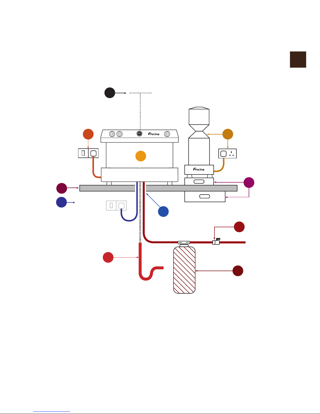
Installation
Overview
3
1
4
7
Cold
Water
(15mm)
Waste
PowerPower
Power
(2nd Position
Switch or plug)
9
10
11
23
8
300mm
11
Please ensure a gap of 300mm is maintained
above the top tray of the machine to allow for
cup storage and service access.
1
Coffee Machine.
2
Grinder – 13 amp socket required.
3
Power connection for coffee machine
(must be within 1 metre). Switch or plug.
4
1.5” (Minimum Diameter) Stand pipe for
waste as for washing machine.
5
¾'' B.S.P Washing machine type valve
for mains cold water with isolator handle.
7
Counter.
8
Under counter or under grinder
Knock-out drawer.
6
Water Softener (DSU) / inline filter
if required.
9
Hole in counter: 2'' Diameter.
10
Alternative position for power supply
(must be within 1 metre). Switch or plug.
Preparing for
Installation
Services and
equipment
required for
installation
A
4
All machines require a mains water & power supply as specied below. It is highly
recommended that a mains waste outlet is provided but a bucket is sufcient if not
available. All services must be in place prior to installation. ALL CALLS TO UNPREPARED
SITES ARE FULLY CHARGEABLE.
Mains water:
15mm mains cold water supply with ¾'' BSP standard washing machine stop cock.
Note: Min inlet water pressure : 100kPa (1 Bar)
Max inlet water pressure : 600kPa (6 Bar)
If water pressure in excess of 600kPa (6 Bar) a Pressure Reducing Valve must be tted.
Mains waste:
1 ½'' (minimum diameter) stand pipe for exi hose.
Water and waste connections to be directly beneath the location of the machine
Power supply: As below
Note: Socket to be located on the same side of the coffee machine that the grinder will
stand. (Recommended right hand side - see installation overview).
Grinders - All models 13amp
Coffee Machines - Standard Power Ratings
Coffee Machines - Alternative Power Ratings
Note: Alternative power ratings must be specied on order if required.
1 Group 2.7kw 13amp
2 Group* 4.0kw 20amp single phase
3 Group 7.5kw 32amp single phase
4 Group 7.5kw 32amp single phase
* Except Bambino which is 2.85KW / 13amp. 4kw available as an
alternative power rating on 20amp single phase supply
Group kw amp
Group kw amp
2 Group 2.85kw 13amp
2 Group* 4.0kw 20amp single phase
2 Group 7.5kw 32amp single phase
3 Group 9.0kw 45amp single or three phase
4 Group 9.0kw 45amp single or three phase
* Bambino model only

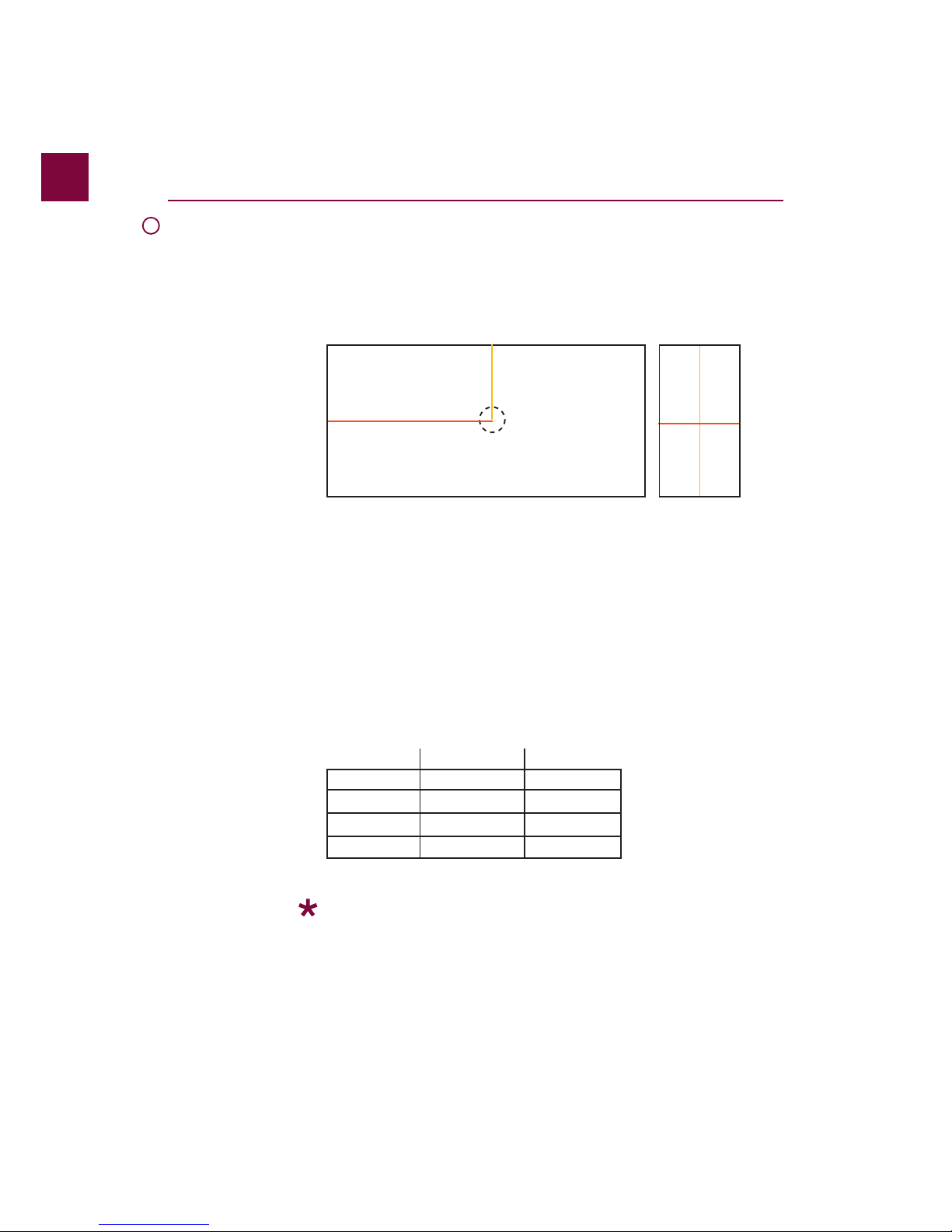
Preparing the area
for installation
(All except
Romano)
5
B
(1) Depth from the back of the machine to the hole.
(2) Length from the side of the machine to the hole.
(3) Hole in counter: 2'' Diameter
(4) Depth needed for grinder
(5) Width needed for grinder
Work out the location of the coffee machine on the bar or counter and find the position.
Drill a 2’’ hole using the measurements below as a guide. All the coffee machines power
and waste connections feed from the bottom at the centre of the coffee machine. These
connections then feed down through the 2’’ hole in the bar or counter.
Note: The power connections for the coffee machine and grinder must be within 1 metre
behind or beneath the machine. The power point must be easily accessible at all times.
The water and waste connections for the coffee machine must be directly beneath it.
All services, including hole in bar counter, must be in place prior to engineer arriving to install
the coffee machine.
Ensure that the surface the coffee machine is to be placed on is sufficiently strong and stable
enough to carry the weight of the coffee machine.
(1) (4)
(3)
(2)
(5)
Plan view for drilling counter for Coffee Machine Area for Grinder
1 Group (1) 110mm (2) 235mm
2 Group (1) 110mm (2) 300mm
3 Group (1) 110mm (2) 400mm
4 Group (1) 110mm (2) 500mm
Grinder (4) 450mm (5) 240mm
Group Depth Length
6
Preparing the area
for installation
(Romano)
C
(1) Depth from the back of the machine to the hole.
(2) Length from the side of the machine to the hole.
(3) Hole in counter: 2'' Diameter
(4) Depth needed for grinder
(5) Width needed for grinder
Work out the location of the coffee machine on the bar or counter and find the position.
Drill a 2’’ hole using the measurements below as a guide. All the coffee machines power
and waste connections feed from the bottom at the centre of the coffee machine. These
connections then feed down through the 2’’ hole in the bar or counter.
Note: The power connections for the coffee machine and grinder must be within 1 metre
behind or beneath the machine. The power point must be easily accessible at all times.
The water and waste connections for the coffee machine must be directly beneath it.
All services, including hole in bar counter, must be in place prior to engineer arriving to install
the coffee machine.
Ensure that the surface the coffee machine is to be placed on is sufficiently strong and stable
enough to carry the weight of the coffee machine.
(1) (4)
(3)
(2)
(5)
Plan view for drilling counter for Coffee Machine Area for Grinder
1 Group (1) 110mm (2) 240mm
2 Group (1) 110mm (2) 360mm
3 Group (1) 110mm (2) 480mm
Grinder (4) 110mm (5) 240mm
Group Depth Length
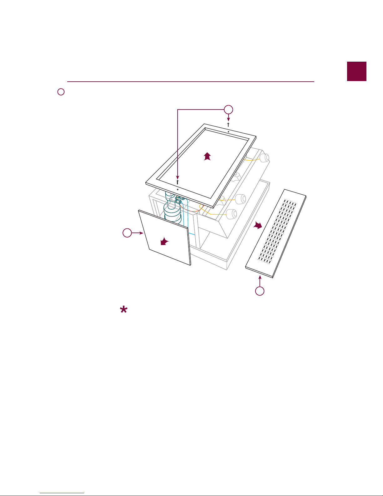
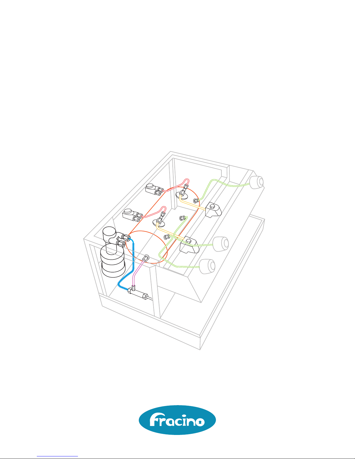
Note: Remove all packaging before working on / installing the machine and remove plastic
protective coating from stainless steel.
All except Romano
1) Remove the top tray of the machine by locating and unscrewing the two M4 screws at
either end of the tray. Carefully lift off the top tray and place somewhere flat.
2)The sides of the machine just need a gentle tug to remove. They are fixed using ball studs
for quick and easy access.
3) Remove the drip tray to reveal the waste funnel. This is done by lifting it upwards at the
front as it simply rests in place again for easy access and cleaning.
Romano only
1) Remove the top tray of the machine by locating and unscrewing the 2 x M5 screws from
each side of the top tray which hold the side panels and the 2 x M4 screws at either end.
Carefully lift off the top tray and place somewhere flat.
2)The sides of the machine just need a gentle tug to remove. They are fixed using ball studs
for quick and easy access.
3) Remove the drip tray to reveal the waste funnel. This is done by lifting it upwards at the
front as it simply rests in place again for easy access and cleaning.
7
Preparing the
machine for
installation
D
2
3
1
8
Installing the
coffee machine
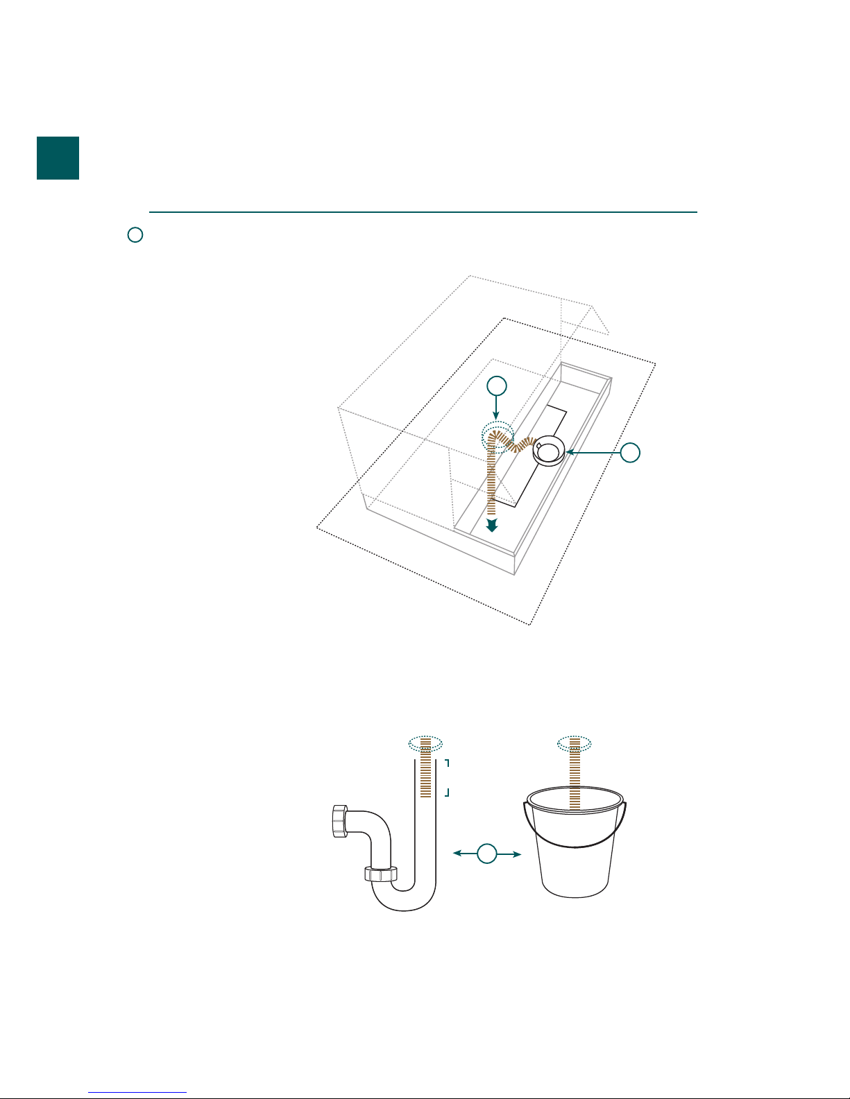
Connecting
the waste
pipe
A
1) Fit the grey push-on flexible waste hose onto the round waste funnel located in the centre
of the machine and tighten with the wormdrive clip provided. 2) Then feed the waste hose
under the machine and down through the 2” hole already cut out. Pull taught and ensure no
kinks are present in pipe.
3) Place the waste pipe into a bucket below the machine or into the stand pipe with a ‘P’ or
‘S’ trap to prevent smell. Ensure waste pipe is cut to length and is only 75mm into the
bucket or stand pipe. It must not touch the bottom as this will block and cause floods under
the machine. Clip or cable tie the pipe into position to prevent it from moving.
1
2
3
75mm
 Loading...