

Page 1
®
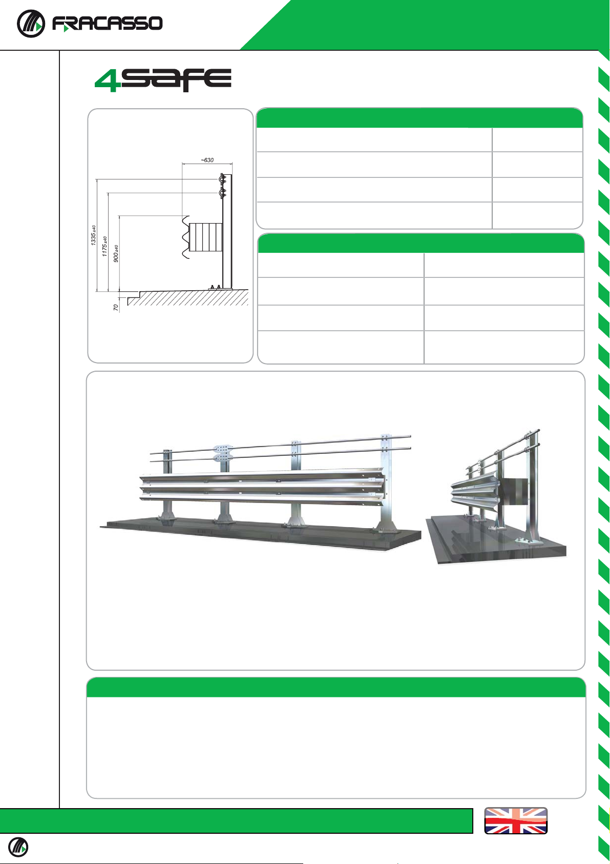
SINGLE SIDED SAFETY BARRIER ON BRIDGE
H4b-A-W6 (3n31622)
Performance
Containment level
Acceleration Severity Index “ASI”
Working width
Extreme lateral position of the vehicle
Characteristics
Height out of ground
Transversal overall dimensions
Centre to centre between posts
Tested minimum length
(without terminal end)
H4b
A
W6 (2,0 m)
2,3 m
1335 mm/1175 mm/900 mm
630 mm
1500 mm
78 m
Description
Supply and erection of a 3-wave safety barrier, thickness 2.5 mm, posts HEA 120 h. 1350 mm with welded plate
300x400x20 mm. Anchor bolts TOGE, fi xed to ground every 1500 mm, spacers 415x80x5 mm L=330 mm, with double
upper threaded retaining bars diam. 32 mm, assembled with nuts and bolts and provided with refl ectors.
S235-S275-S355JR-FeB44K steel quality according to EN 10025
Hot dip galvanization according to EN ISO 1461:2009
Nuts and bolts according to EN ISO 898 – EN 20898 – UNI 3740/6
All particulars are in accordance with crash tests requirements.
Revision 2 of 28/04/2010
Technical Documentation
Via Barbariga 7, 30032 Fiesso d’Artico (VE) Italy Tel +39 049 9899111 Fax + 39 049 504619 - [email protected] - www.fracasso.it
Page 2
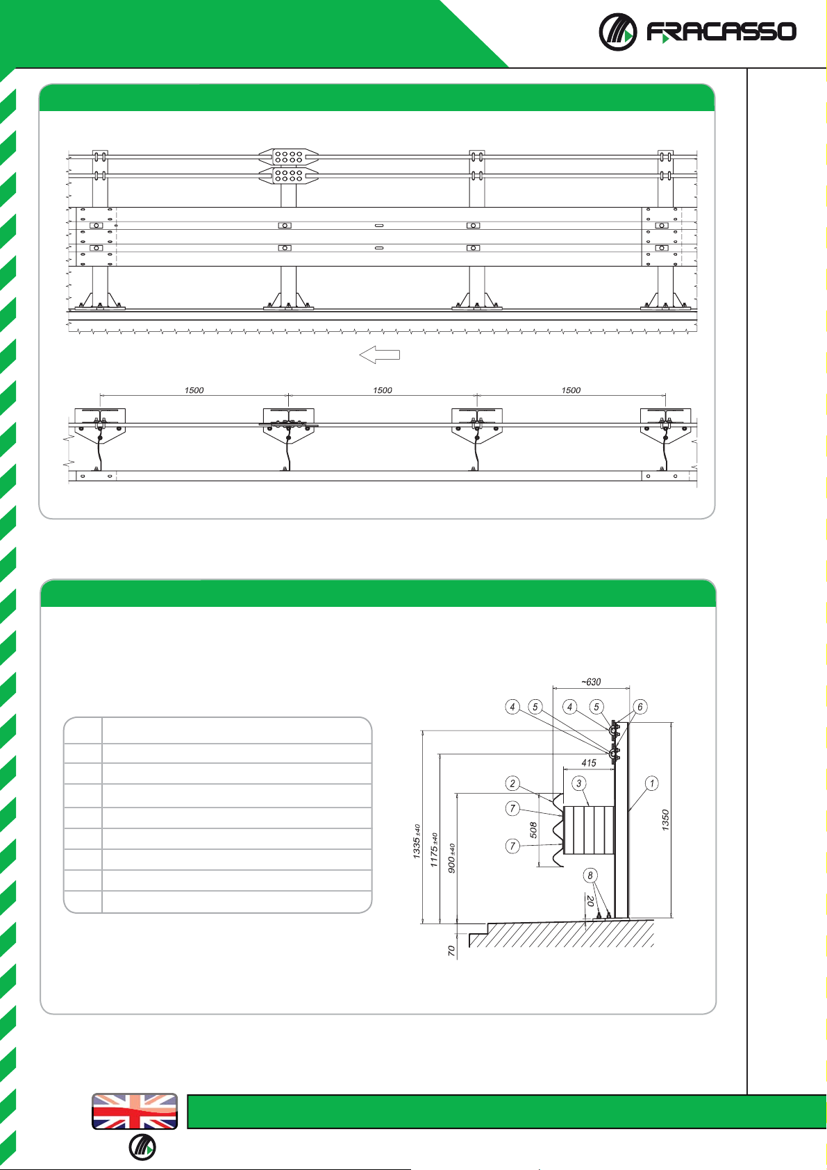
Elevation
Description
1
Post HEA120 h=1350 mm + welded plates
2
“3n” Beam c/c 4500 mm th. 2,5 mm
3
Spacers 415x80x5 mm L=330 mm
Clamp M16 4
Upper thr. ret. bars Ø 32 mm L=9250 mm with welded plate
5
Plate 100x40x5 mm
6
Cover plate 100x45x5 mm
7
Anchor bolts M18 TSM B16 cl.10.9 L=190 mm
8
Section
Via Barbariga 7, 30032 Fiesso d’Artico (VE) Italy Tel +39 049 9899111 Fax + 39 049 504619 - [email protected] - www.fracasso.it
Page 3
®
SINGLE SIDED SAFETY BARRIER ON BRIDGE
H4b-A-W6 (3n31622)
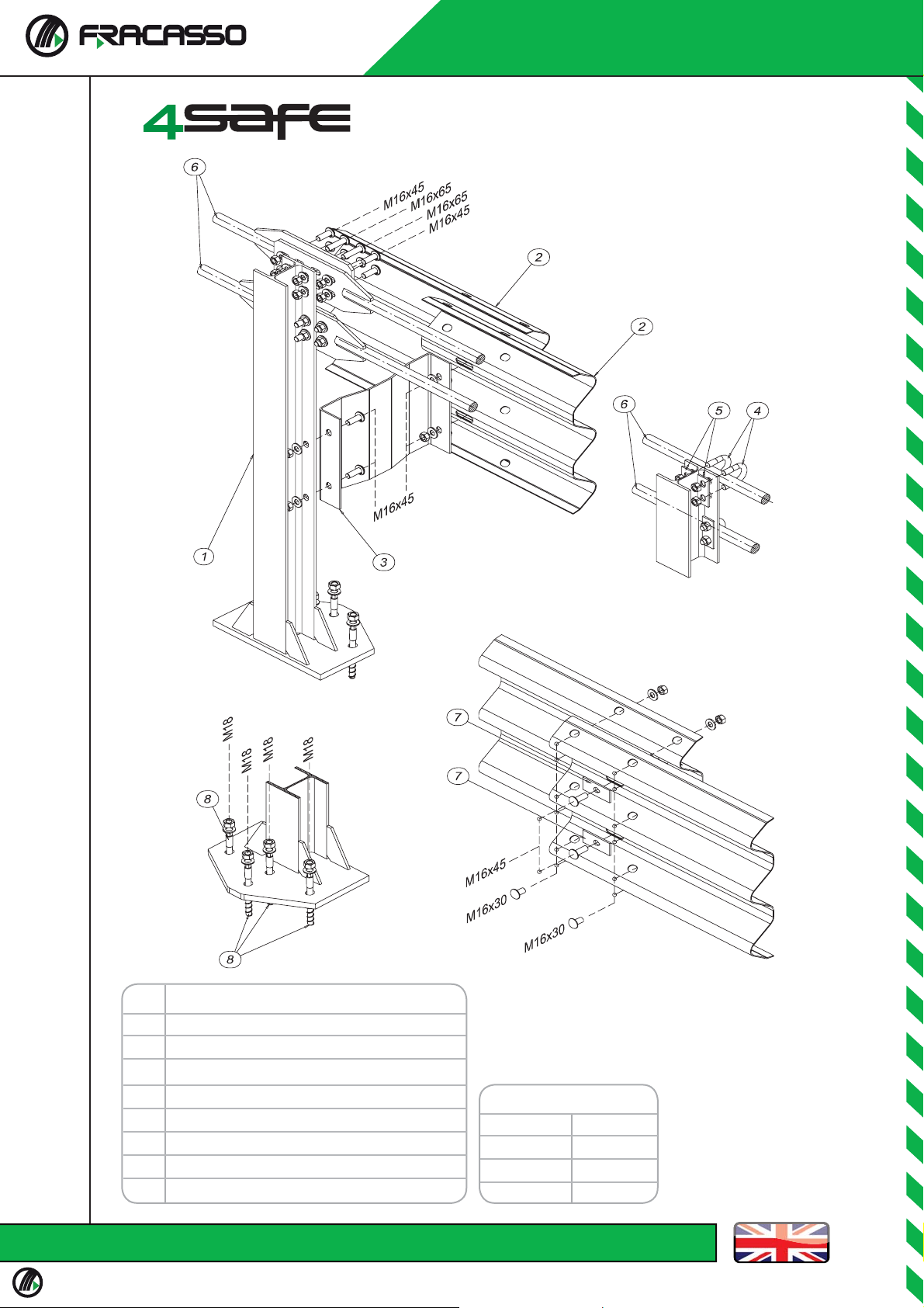
Description
1
Post HEA120 h=1350 mm + welded plates
2
“3n” Beam c/c 4500 mm th. 2,5 mm
3
Spacers 415x80x5 mm L=330 mm
Clamp M16 4
Upper thr. ret. bars Ø 32 mm L=9250 mm with welded plate
5
Plate 100x40x5 mm
6
Cover plate 100x45x5 mm
7
Anchor bolts M18 TSM B16 cl.10.9 L=190 mm
8
Torque value
M16 x 30
M16 x 45
90 Nm
90 Nm
90 NmM16 x 65
40 NmM18
Revision 2 of 28/04/2010
Via Barbariga 7, 30032 Fiesso d’Artico (VE) Italy Tel +39 049 9899111 Fax + 39 049 504619 - [email protected] - www.fracasso.it
Page 4

INSTALLATION CRITERIA FOR 4Safe BARRIER H4b W6 A (3n31622)
In concomitanza con le norme generali di montaggio specifi cate nel capitolo introduttivo vanno osservate le seguenti
linee guida per l’installazione della barriera 3n31622.
Preliminary operations
Where installation is to be carried out in traffi c, all necessary road signs must be set up in order to direct traffi c and
protect workers from vehicles, in accordance with safety regulations.
The parts making up the road barrier can be unloaded from the transport vehicles by means of a crane fi tted to the
vehicle, or forklift truck, in accordance with current safety regulations.
Workers must be supplied with all required equipment, including safety shoes, gloves and goggles and - where
necessary - helmets, safety harnesses and all else specifi cally needed for the site and required by current safety
regulations.
Installation sequence
The assembly diagram provides instructions for correct barrier installation. Fully and completely follow these
instructions.
Main steps:
1. Trace out a full line of reference on the ground, which will serve to align mounts, beams, and all other
longitudinal parts.
2. Place the beams (2) along the traced line taking into account the direction of traffi c.
3. Prepare the anchor rod holes 1500 mm apart and install the M18 TSM B 16x190 mm (8) anchoring screws
as follows:
Drill a hole with an electric drill and 16 mm bit to the recommended 130 mm depth
Remove dirt from the hole using compressed air.
Brush the hole interior using a 18 mm diameter brush.
rimuovere ancora con aria compressa la polvere dall’interno del foro.
Starting from the bottom, fi ll the hole with the chemical anchoring component.
Insert the anchor rod in the hole and screw it in with an impact screwdriver, with minimum
40 Nm torque.
When the screw reaches the bottom of the hole, a small part of the previously injected
chemical anchoring component should seep out.
In case the chemical component does not seep out, this means that an insuffi cient quantity was
injected. In this case, unscrew the anchor rod and inject more of the chemical anchoring
component.
Screw in the anchor rod with the impact screwdriver with minimum 40 Nm torque.
4. The uprights HEA120 h=1350 mm (1) are vertically lifted and fastened to the base at the anchoring rods,
screwing the lock nut onto the anchoring rod.
5. Apply the upper barrier (6) on the upright using the clamps(4). At the joint between the two subsequent
barrier elements, connect the plates between them using 8 bolts: 6 M16x45 mm bolts and 2 M16x65 mm
bolts, which are also used to connect the plates to the corresponding upright.
6. Apply the second lower barrier (6) on the same side of the upright following the instructions above and
keeping joints between barriers at the same pole.
7. Assemble the spacers (3) on the two sides of the upright using the M16x45 mm bolts;
8. Assemble the beams (2) that have been laid on the ground, attaching them to the spacers (3) and
themselves, by means of the bolts supplied and the set plates.
9. Use the calibrated pneumatic screwdrivers to fasten all nuts and bolts into place, checking levels and
alignments.
10. Installation must always take place under the surveillance of a specialist technician, and in full
compliance with the fi nal drawing and current safety regulations.
Via Barbariga 7, 30032 Fiesso d’Artico (VE) Italy Tel +39 049 9899111 Fax + 39 049 504619 - [email protected] - www.fracasso.it
Page 5

Inspection of installation conformity
The technician responsible for the installation shall, at the very least, control conformity of the following, prior
to beginning assembly, during work and upon conclusion, by using all measurement instruments necessary and
in his possession:
1. Full compliance of the installation with the fi nal drawings of reference.
2. Pole spacing and height of upper beam and current edge in accordance with that specifi ed on the
fi nal drawings of the barrier, dilation joints and ends.
3. Length and alignment of the installation on the basis of the fi nal drawings and the road layout and
altimetry.
4. Final coupling bolt torque according to that set in the assembly diagram.
5. Compliance with all applicable safety regulations.
Revision 2 of 28/04/2010
Via Barbariga 7, 30032 Fiesso d’Artico (VE) Italy Tel +39 049 9899111 Fax + 39 049 504619 - [email protected] - www.fracasso.it
 Loading...