

2018.03
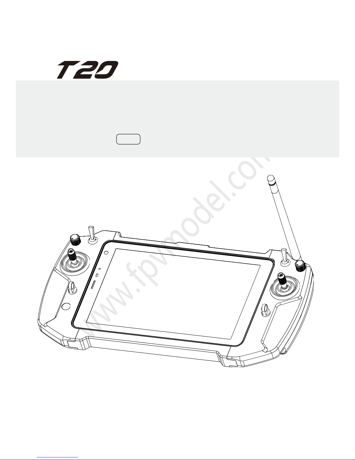
All-in-one Handheld Ground Station
User Manual
v 1.1

INDEX
Disclaimer
...................................................................................................................... 1
Cautions
.........................................................................................................................1
Installation note
...................................................................................................... 1
Precautions for Use
...............................................................................................1
Introduction..................................................................................................................2
Check List....................................................................................................................... 2
Product Diagram
........................................................................................................3
Receiver parts
.........................................................................................................3
Remote Controller Parts
...................................................................................... 4
Receiver Installation Guide
.................................................................................5
Remote Controller Operation
............................................................................. 6
Tablet Computer Power ON and OFF
............................................................. 6
Remote Controller Power ON and OFF
.......................................................... 6
Remote Controller Alarms
................................................................................... 6
Remote Controller & Receiver Indicators
....................................................... 7
Remote Control Assistant Software Operation
....................................... 8
Channel monitoring and calibration
................................................................. 8
Channel configuration
.......................................................................................... 9
Receiver pairing and configuration
.................................................................10
Remote Controller Charging............................................................................. 12
FAQ .................................................................................................................................13

1
Disclaimer
Thank you for choosing T20 All-in-one handheld ground station.(Hereinafter to
be referred as "T20". Please use T20 according to your local radio regulation. Please
read this statement carefully before use. It is deemed as acceptance of the entire
contents of this statement,once the product has been used.Please strictly follow
this instruction to install and use the product. FPV MODEL Co., Ltd. do not accept
any legal responsibility and will not be liable for any result or loss caused by
improper use, installation, assembly or modification of users.
Cautions
When using the T20, if it is not operated properly, the aircraft may cause a certain
degree of injury or damage to property. Please be careful when using it.
Installation note
1. Be sure to use the parts provided by FPV MODEL.
2. Be sure to install the antenna before power on to avoid damage to
the circuit.
3. Be sure the antenna is not obstructed by any obstacles and the end of the
antenna is facing down vertically and no bent, to avoid the communication
distance being shortened, or even unable to communicate.
4. Do not disassemble or modify the T20. If you encounter any problems that
cannot be solved during the installation process, please contact FPV MODEL
Co., Ltd. or your local distributor.
5. Be aware of the proper distance between all the electronic devices during
installation, to minimize the electromagnetic interference between the
devices.
Precautions for Use
1. Before use, please make sure all the connecting wires are tight and all parts
are working properly.
2. Please open the remote controller configuration software and check if the
channels are all working after booting.
3. Please check the surrounding environment to ensure that there are no
other device interference in 840MHz-930MHZ , otherwise T20 data
transmission performance may be seriously affected.
4. Check the remote controller battery before use. If the battery is lower than
25%, please recharge the remote controller. If the remote control is turned off,
the receiver will go out of control.
2
Introduction
T20 is a water, sun & shock resistant handheld ground station that integrates
an industrial-grade computer with Windows system and an integrated link remote
control system.The transmitter can be used to control the aircraft or a gimbal with
real-time flight and remote status feedback, route planning, and other functions. It
supports most of the ground station software on the market. The industrial grade
computer and military grade transmission links not only ensure the safety and
stability of the aircraft,but also are simple to operate and easy to carry.
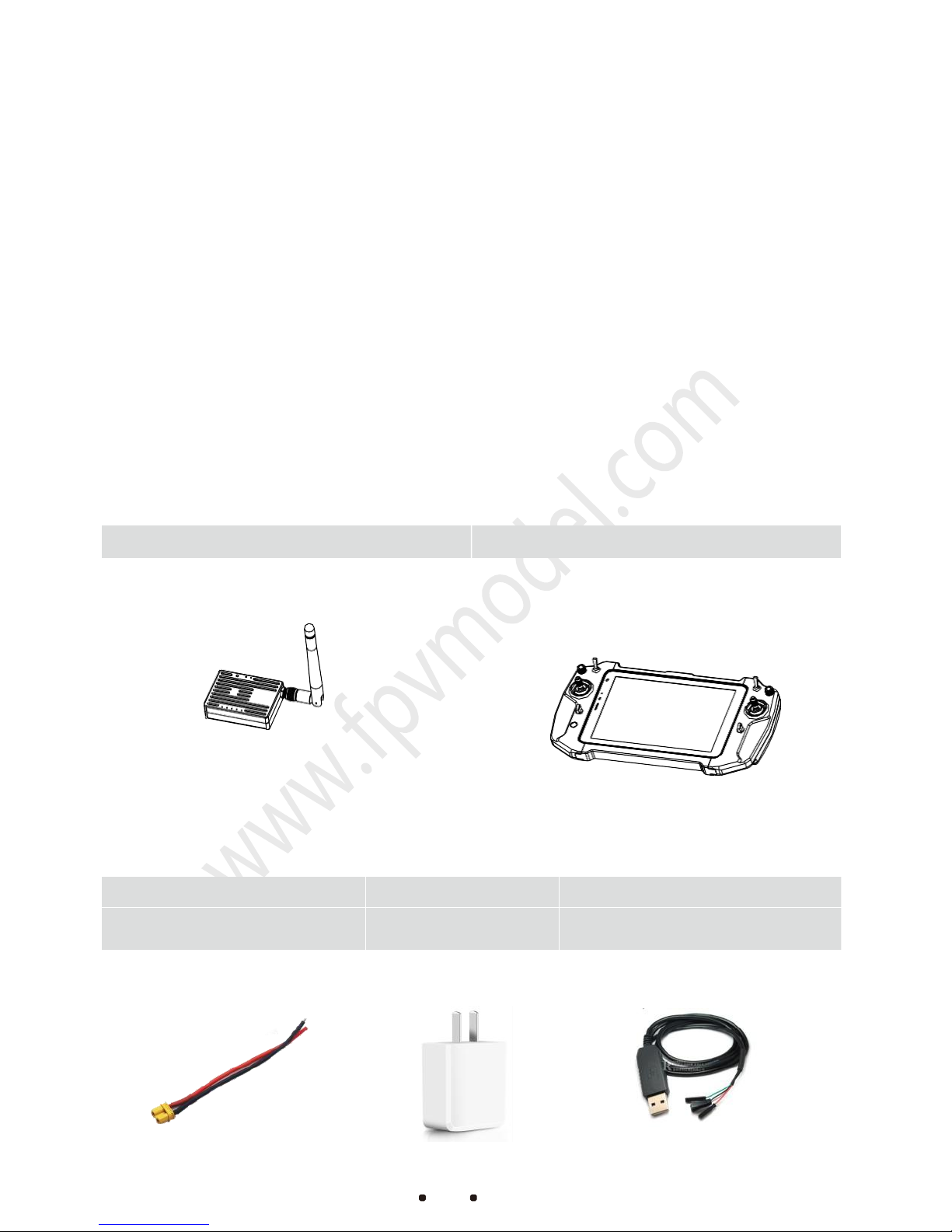
Check List
Main modules
Accessories
Power cord
Power adapter
Receiver paring cable ×1
Charge the receiver
(DC:7.4-12V)
Charge the Remote
Controller
Used for frequency paring
and parameter setup
Receiver ×1
Remote Controller x 1
3
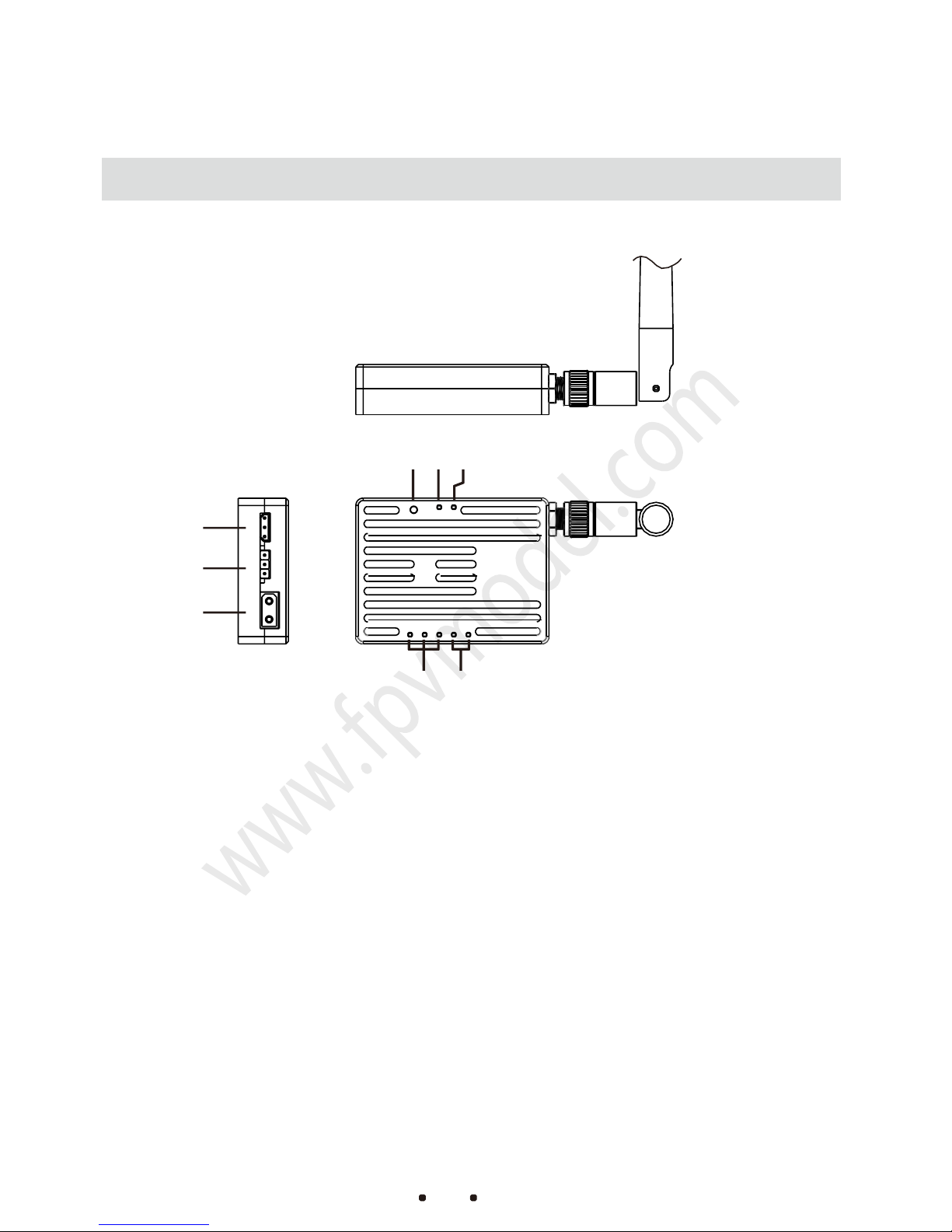
Product Diagram
Receiver parts
⑥ ⑦ ⑧
③
②
①
④ ⑤
①Power port
Use XT30 power plug,Supply voltage:7.4-12V
②S-BUS port
Use a servo wire to connect the S-BUS port of a flight controller or other equipment
③COM port
The COM port is TTL ,used to connect to the COM or API port of a flight controller
④Signal strength indicators
S1 S2 S3 are signal strength indicators
⑤Data transmission indicator
When the RXD light is on, it indicates that the receiver is receiving data.
When the TXD light is on, it indicates that the receiver is transmitting data.
⑥Set button
Used to configure the radio module or pair with the remote controller
⑦Radio configuration mode indicator
It indicates if the receiver is in configuration mode
⑧Link indicator
It indicates whether the link communication between the receiver and the remote controller is normal

4
Remote Controller Parts
⑤ ⑥ ⑦ ⑧ ⑩ ⑨
④
⑪
③
②
⑫
①
①Remote Controller
Power Button
Turn on and off the
remote controller
②Computer Power Indicator
Indicates computer power and
whether it is charging
③Joystick
Control flight status (There are 4 joystick
modes that can be setup by built-in
software)
④Auxiliary Channel Switch
SA and SB are three-gear switches, LD
and RD are knobs
⑦TF Card Slot
Used to read TF cards
⑩SMA Jack
For antenna installation, SMA female
connector
⑤Computer Power Button
Turn on and off the tablet computer
⑧SIM Card Slot
Used to insert SIM cards to enable
internet access on tablet
⑪
Type-C Charging Port
For charging the tablet.The maximum
charging current is 3A(The tablet and
remote controller can be used while
charging)
⑥Volume +/-
Increase or decrease the tablet volume
⑨Auxiliary Channel Switch
SA and SB are three-gear switches
⑫Standard USB2.0 Port
For external keyboard, mouse or other
devices.

5
Receiver Installation Guide
1. Tighten and install the antenna to the transmitter SMA connector.
2. Fix the transmitter to the plane, with the antenna vertically down
Figure 1-1
3. As shown in Figure 1-1, use the servo wire to connect the COM port and S-
BUS of the transmitter with other devices.
RX TX S S
Receiver GND GND
FC or other
Receiver+
+
FC or other
TX RX devices
-
-
devices
4.
Connect to a stable 7.4-12V DC Power supply.Ensure that the supply
current is greater than 2A. When the L1 indicator flashes blue, it
indicates that the transmitter and remote controller are connected
properly.
The receiver power is 1W. Please keep the receiver antenna away from other electronic devices
(GPS, compass, etc.) to avoid interference with flight.
Make sure to install the antenna before power on,otherwise the radio module may get burned
Try to get the antenna upside down and avoid obstructed obstacles when using, to avoid
communication distance shortened and even unable to communicate.
Be sure to use the specified model of antenna to properly install and use. Do not use other
types of antenna
DC:7.4~12V
TXGNDRX
- + - +
TX GNDRX
Flight
Controller
S-BUS
COM
- +
- +

6
Remote Controller Operation
Tablet Computer Power ON and OFF
1. Press and hold the computer power button.When you see the startup
screen, release the button.
2. After the computer is turned on, you can check the remaining power
through the battery indicator in the lower right corner of the desktop. If
the power is less than 20%, please charge it in time.
3. After using the computer, you can shut down the computer through the
computer shutdown interface.
If the computer cannot be turn on by long-pressing the power
button, please use the charger to recharge the computer to
activate and try it again.
Remote Controller Power ON and OFF
Remote Controller Alarms
Low Battery:When the battery level is detecte d to be 3.65V,the remote controller
will sound a “bee p-beep”al a rm and th e remote control ler power indica t or will flash
red. Whe n the bat tery leve l is low er than 3.65v, the remote co n troller will
automatically sh u tdown for protection。
No opera t ion for a long time :When the joystick s or th e switches have no operations
on them for 10 mi nutes, the remote control ler will sound a contin uous “bee p-beep”
alarm . At this time, if any joys ticks or switch es are toggled, the alarm sound will be
automatically sh u t down.
If the computer is not in use for a long time, please turn it off to avoid standby
power consumption.
Press and hold for 5
secs to turn it on/off

7
Remote Controller & Receiver Indicators
Remote Controller Indicators
Indicator
Prompt tone
Status
Solid Red
D-long tone
Boot Successfully
Red goes out
D-long tone
Shutdown Successfully
Flashing Red
D-D-D...
Low Battery Alarm
Receiver Indicators
Indicators
Status
L1
Flashing Blue
The receiver and remote controller are
connected successfully
L2
Solid Blue
The receiver is currently in configuration
mode and has no power output
RXD
Flashing Yellow
The receiver is receiving data
TXD
Flashing Yellow
The receiver is receiving data
S
1 、S2 、S3
Flashing Red
High signal quality
S
2、S
3
Flashing Red
Medium signal quality
S3
Flashing Red
Low signal quality

8
Remote Control Assistant Software Operation
Channel monitoring and calibration
Figure 1-2
1. Turn on the remote controller and computer power button, and then
open tablet remote control assistant software.
2. Figure 1-2 is the monitor interface. Toggle each switch or joystick to
check if they are working.
3. Click on “CALIB”button. Then toggle the joysticks and rotate the knobs
maximally in 10 seconds.Now the software will collect the maximum value of
each joystick or knob and perform calibration (the factory has already
calibrated before delivery)

9
Channel configuration
Figure 1-3
1. Click on “Function” button. The channel configuration interface is
shown as figure1-3. CH01-CH04 are default flight channels and
CH05-CH14 are auxiliary channels
2. The configuration of REVERSE, SUB-TRIM and END POINT are the same
as common remote controller setting method.(Please refer toFUTABA
remote controller setting)
3. “FAIL SAFE” setting: Click on the white checkbox.When there is a √
in the white checkbox,the loss of control protection is working in that
channel.Set the value in corresponding input field with specified
output pwm value when the protection is enabled.
(After setting up,
please connect the receiver to your flight controller and switch off the
rem ote controller to ch eck if th e calibration is correct.)
4. The red marked box in Figure1-3 is the physical joystick configuration
outputs corresponding to CH5 - CH14. (One channel can be set to
one single joystick or multiple ones at once)
“Read data”Button:Read current configuration file
“Write data ” Button:Write new configuration data
“Load cfg”Button:Load a different saved configuration file
“Save dfg”Button: Save the current configuration to a file for loading next time
After changing the configuration each time, you need to click the Write Data
button. The changed configuration will take effect.
The remote controller and the receiver have been paired before leaving the
factory. Do not re-pair and configure them without special circumstances.

10
Receiver pairing and configuration
Figure 1-4
1. As shown in figure 1-4,Before the receiver is powered on, long press
the SET button with a pin until the L2 indicator lights up solid blue,
and then release.
2. As shown in figure 1-5,connect the receiver and remote controller using
the equipped configuration cable.
Figure 1-5

11
3. Turn on the remote controller and open the assistant software. Click
on“Link” button, then the interface will be shown as in Figure 1-6.
Figure 1-6
4. When changing any value of remote contr oller or receiver, the
corresponding receiver or remote control value will change too.
“Change ID”:The receiver and remote controller IDs will be changed
randomly at the same time after clicking this button.
“Refresh Data”:After modifying the data, click “Refresh Data”
button to see if the data is displaying correctly.
When using two remote control devices at a same site, please set the
communication channel to a different value
The default communication bandwidth is 100k. Please do not alter it
if you do not have sufficient RF knowledge.
When the software is in the “Link” interface, the radio is in
configuration mode and there is no transmitting power output. Please
exit the interface after configuration.
Configuration parameters can be modified only if the assistant software
reads data both from the remote controller and receiver at the same
time.

12
Receiver Parameters
Name
Modification
method
Value
Comment
Device ID
Random
0-65535
Unique ID code for pairing
between receiver and
remote controller
Serial baud
rate
Manually
modify
1200、2400、4800、
9600、
19200、3400、57600、
115200
This baud rate setting needs to
be set according to the required
baud rate for the flight control
(default is 115200)
Channel
Manually
modify
1-8
Bandwidth
Manually
modify
100K、200K
The default is 100K. The larger the
bandwidth is, the closer the
communication distance is.
Transmit
power
Manually
modify
30DBM 1W
29DBM 0.8W
27DBM 0.5W
24DBM 0.25W
20DBM 0.1W
The default is 1W. The greater the
power is, the longer the
communication distance is.
Remote Controller Charging
1. Please use the standard charger for charging.(Charging:5V-3A)
2. If there is no time to use a charger, you can use a power bank to charge
the remote controller. The remote controller can be used while charging.
3. The computer indicator will indicate solid red when charging and will go
out after full charge.
4. If you do not use it for a long time after fully charged, Please turn off the
computer to avoid standby power consumption.

13
FA Q
1:Q: When pressing the remote controller power, there is no “beep” boot
sound and the power indicator only flash red one time.
Please confirm whether the tablet has enough battery.
2:Q: Receiver powers up normally but there is no signal output.
Please make sure the ID, channel, and airspeed of the receiver are set to be
the same as the ones of the remote controller.
3:Q: The receiver SBUS has a signal output, but the serial port is not able to
connect, or the transmission signal is garbled.
Please make sure the serial port baud rate of the remote controller and the
receiver are the same and set the corresponding baud rate of the ground
software.
4:Q:There is interference when two or more devices are working at the same
time.
Please note that the ID of each set must be different and the channels must
be set to different signals to avoid any interference.
 Loading...