

FPS 9650 Series Installation And Maintenance Manual

9650 Valve Series
Fossil Power Systems Inc.
10 Mosher Drive
Dartmouth
Nova Scotia, Canada,
B3B 1N5
Tel: 1 902 468 2743
Fax: 1 902 468 2323
E-mail: support@fossil.ca
Installation
And Maintenance Manual
July 2019

9650 Valve Series
Installation and Maintenance Manual
9650 Valve Series
Instruction Manual
9640-1103
Last Revised: July, 2019
Copyright 2017 - 2018 Fossil Power Systems Inc. All rights reserved.
All trademarks referenced herein are property of their respective corporation.
The information contained herein is subject to change without notice.
2

9650 Valve Series
Installation and Maintenance Manual
About this Manual
This instruction manual describes the installation and maintenance of the 9650 Valve Series as supplied
by Fossil Power Systems Inc.
Although care was exercised to make this Manual specific and complete, it is not intended that it should
cover all potential operating and maintenance conditions. It must be recognized that no amount of
written instruction can replace intelligent thinking and reasoning on the part of qualified personnel. It
is the responsibility of operations and maintenance personnel to become completely familiar with the
mechanical, electrical and control systems involved, including their characteristics and performance
under various operating conditions.
This knowledge can be obtained through the basic information provided in this manual, supplemented
by field experience and by advice and recommendations from this Company’s field agents.
3

9650 Valve Series
Installation and Maintenance Manual
TABLE OF CONTENTS
1 OVERVIEW .................................................................................................................................................... 6
1.1 AUTOMATIC VALVES ................................................................................................................................ 6
1.1.1 Definition ....................................................................................................................................... 6
1.2 MANUAL VALVES ...................................................................................................................................... 6
2 SPECIFICATIONS ............................................................................................................................................ 8
2.1 CSA AUTOMATIC GAS VALVE OPERATING SPECIFICATIONS ..................................................................... 8
2.2 CSA MANUAL GAS VALVE OPERATING SPECIFICATIONS ........................................................................... 8
2.3 FM AUTOMATIC LIQUID & GAS VALVE OPERATING SPECIFICATIONS ....................................................... 8
2.4 ALL OTHER VALVE OPERATING SPECIFICATIONS ...................................................................................... 8
3 SOLENOID ..................................................................................................................................................... 9
3.1 GENERAL INFORMATION .......................................................................................................................... 9
3.2 STANDARD SOLENOID AIR SUPPLY SPECIFICATIONS ................................................................................ 9
3.3 LOW PRESSURE SOLENOID AIR SUPPLY SPECIFICATIONS ......................................................................... 9
3.4 SOLENOID VOLTAGE / RATING FOR ASCO & PARKER SOLENOIDS........................................................... 10
3.5 MAINTENANCE (NAMUR MOUNT SPOOL TYPE SOLENOID) - REPLACING SOLENOID ............................. 12
3.6 MAINTENANCE (POPPET TYPE SOLENOID) - REPLACING SOLENOID ....................................................... 16
4 LIMIT SWITCH ............................................................................................................................................. 18
4.1 GENERAL INFORMATION ........................................................................................................................ 18
4.2 LIMIT SWITCH WIRING ........................................................................................................................... 18
4.3 LIMIT SWITCH CONTACT RATINGS .......................................................................................................... 19
4.3.1 FPS 10 - WATERTIGHT LIMIT SWITCH (FPS PN 6010-1008) ......................................................... 19
4.3.2 FPS 20 - EXPLOSION PROOF LIMIT SWITCH (FPS PN 6010-1009) ................................................ 19
4.4 MAINTENANCE - REPLACING LIMIT SWITCH ........................................................................................... 20
4.5 CSA CLOSED/PROOF OF CLOSURE LIMIT SWITCH ................................................................................... 26
5 ACTUATOR .................................................................................................................................................. 27
5.1 GENERAL INFORMATION ........................................................................................................................ 27
5.1.1 ACTUATOR AIR SUPPLY SPECIFICATIONS ..................................................................................... 27
5.1.2 DOUBLE ACTING ACTUATOR- TORQUE ....................................................................................... 27
5.1.3 SPRING RETURN ACTUATOR- TORQUE ........................................................................................ 27
5.2 MAINTENANCE - REPLACING ACTUATOR ............................................................................................... 28
6 BALL VALVE ................................................................................................................................................ 30
6.1 GENERAL INFORMATION ........................................................................................................................ 30
6.1.1 SERIES 88 BODY BOLTS- TORQUE ................................................................................................ 30
6.1.2 SERIES 90D BODY BOLTS- TORQUE .............................................................................................. 30
6.1.3 SERIES 88 STEM NUT- TORQUE ................................................................................................... 31
6.1.4 SERIES 90D STEM NUT- TORQUE ................................................................................................. 31
6.2 MAINTENANCE – 3 PIECE THREADED/SOCKET WELD VALVES ................................................................ 32
6.2.1 EXPLODED VIEW OF THREADED / SOCKET WELD VALVE ............................................................. 34
6.3 MAINTENANCE – 2 PIECE FLANGED VALVES ........................................................................................... 35
6.3.1 EXPLODED VIEW OF FLANGED VALVE ......................................................................................... 37
7 VALVE TESTING ........................................................................................................................................... 38
7.1 REPLACEMENT OF SOLENOID, ACTUATOR OR DISASSEMBLY OF VALVE BODY ....................................... 38
4

9650 Valve Series
Installation and Maintenance Manual
7.1.1 ALL VALVE ASSEMBLIES: .............................................................................................................. 38
7.1.2 CSA APPROVED VALVE ASSEMBLIES: ........................................................................................... 38
7.1.3 FM APPROVED & NON-APPROVED VALVE ASSEMBLIES: ............................................................ 39
7.2 REPLACEMENT OF LIMIT SWITCH ........................................................................................................... 39
8 TROUBLE SHOOTING ................................................................................................................................... 40
9 GENERAL DIMENSIONS ............................................................................................................................... 41
10 SPARE PARTS .............................................................................................................................................. 42
5

9650 Valve Series
Installation and Maintenance Manual
1 OVERVIEW
1.1 AUTOMATIC VALVES
The FPS automatic valve assembly consists of an FPS Fire-Safe Ball Valve, FPS Rack & Pinion/Scotch Yoke Type Spring
Return or Double-Acting Actuator, ASCO Solenoid Control Valve and FPS Rotary Type Limit Switch.
Available Certifications:
CSA 6.5-2000/ANSI Z21.21-2015 – Automatic Valves for Gas Appliances
CGA 3.9-M94 – Automatic Safety Shut-off Gas Valves
CSA – Commercial / Industrial (C/I)
API 607 4th Edition Fire Safe
FM Class 7400 – Liquid and Gas Safety Shutoff Valves
The following sections of this manual discuss in detail the individual components which comprise the automated
valve assembly.
1.1.1 Definition
Automatic valves are available in both normally open and normally closed variations. The assembly is comprised of
the same parts for normally open and normally closed valves so it is imperative to follow assembly procedures
properly and take care while assembling the valve.
Normally closed valves fail to a closed position when power is lost to the automatic valve.
Normally open valves fail to an open position when power is lost to the automatic valve.
1.2 MANUAL VALVES
FPS manual valves may be supplied as CSA/API approved for use with natural gas or propane, or the valves may be
supplied without specific approvals.
Available Certifications:
API 607 4th Edition Fire Safe
CSA Interim Requirement No.60 – Lever Operated Gas Shut-Off Valves
CSA 3.16-15
Section 6 of this manual details and discusses the specifications of the ball valves, and their maintenance.
6
9650 Valve Series
CAUTION
CAUTION: Never place any part of your body inside the valve at any time. Unexpected actuation of the valve
will result in the valve ball turning causing severe personal injury.
CAUTION: De-pressurize system and turn off electrical power to the valve before attempting repair.
CAUTION: Label all wires and air connections prior to disconnection when servicing valves. Wiring and/or air
connection errors can cause improper and dangerous operation.
CAUTION: Verify Proper Operation after servicing.
CAUTION: All wiring to valve must conform to National Electrical Code, ANSI/NFPA 70 and or Canadian Electrical
Code CSA C22.1, Part 1.
Installation and Maintenance Manual
IT IS THE SOLE RESPONSIBILITY OF ANY USER TO ENSURE PROPER VALVE OPERATION AND INTEGRITY AFTER
SERVICING. FPS BEARS NO RESPONSIBILITY, EXPRESSED OR IMPLIED FOR CLAIMS OR LIABILITIES ARISING OUT OF
IMPROPER USE OR INADEQUATE SERVICING OF THE VALVE ASSEMBLIES.
7

9650 Valve Series
Installation and Maintenance Manual
2 SPECIFICATIONS
2.1 CSA AUTOMATIC GAS VALVE OPERATING SPECIFICATIONS
Maximum Operating Pressure: 1380kPa (200psig)
Maximum Ambient Operating Temperature: 50°C (122ºF)
Minimum Ambient Operating Temperature - 45°C (-49ºF)
Mounting: Multi-position
Flow: Bi-Directional
Materials: CF8M or WCB Valve Body; 316 S/S Ball;
Stem and Hardware
Actuator: Spring Return
2.2 CSA MANUAL GAS VALVE OPERATING SPECIFICATIONS
Maximum Operating Pressure: CSA Interim Requirement 60: 1380kPa (200 psig)
CSA 3.16 860 kPa (125 psig)
Maximum Ambient Operating Temperature: 65°C (149ºF)
Minimum Ambient Operating Temperature: - 40°C (-40ºF)
Mounting: Multi-position
Flow: Bi-Directional
Materials: CF8M or WCB Valve Body; 316 S/S Ball;
Stem and Hardware
2.3 FM AUTOMATIC LIQUID & GAS VALVE OPERATING SPECIFICATIONS
Maximum Operating Pressure: 1380kPa (200psig)
Maximum Ambient Operating Temperature: 60°C (140ºF)
Minimum Ambient Operating Temperature: - 10°C (14ºF)
Mounting: Multi-position
Flow: Bi-Directional
Materials: CF8M Valve Body; 316 S/S Ball;
Stem and Hardware
Actuator: Spring Return
2.4 ALL OTHER VALVE OPERATING SPECIFICATIONS
Maximum Operating Pressure: Consult Factory
Maximum Ambient Operating Temperature: Consult Factory
Minimum Ambient Operating Temperature: - 45°C (-49ºF)
Mounting: Multi-position
Flow: Bi-Directional
Materials: CF8M or WCB Valve Body; 316 S/S Ball;
Stem and Hardware
Actuator: Spring Return or Double Acting
8

9650 Valve Series
Installation and Maintenance Manual
3 SOLENOID
3.1 GENERAL INFORMATION
FPS’s valve range includes both spool and poppet type solenoids depending on the particular valve.
The spool solenoid valve body is made of anodized aluminum that mounts directly to the spring return or doubleacting pneumatic valve actuator, which has been manufactured to accept the NAMUR pattern of mounts and port
holes.
Poppet solenoid valve bodies mount to the limit switch of the valve. These are tubed with stainless steel to the
actuator. Wiring is terminated at the limit switch terminal block.
Various voltages are available for seamless system integration. Explosion proof and low power models are also
available to meet the specific application needs (see specification table – page 6).
Media filtration: Filtration to 5 microns is recommended in all cases. Foreign material in the media may cause
excessive leakage, wear or in exceptional cases, malfunction. Install the filter on the inlet side as close to the valve
as possible. Clean periodically depending on service condition.
Lubrication: Lubrication is not required.
Coil Temperature: Valves are supplied with coils designed for continuous duty service. Normal free space must be
provided for proper ventilation. When the coil is energized continuously for long periods of time, the coil assembly
will become hot. The coil is designed to operate permanently under these conditions. Any excessive heating will be
indicated by smoking and/or odour of burning coil insulation.
3.2 STANDARD SOLENOID AIR SUPPLY SPECIFICATIONS
Non-corrosive lubricated or non-lubricated air or other inert gas
Min 414 kPa (70psig)
Max 828 kPa (120psig)
3.3 LOW PRESSURE SOLENOID AIR SUPPLY SPECIFICATIONS
Non-corrosive lubricated or non-lubricated air or other inert gas
Min 345 kPa (50psig)
Max 414 kPa (70psig)
9

9650 Valve Series
MODEL/
MODEL #
VOLTAGE
FPS PN
RATING
Inrush
Current
Steady
State
Current
ASCO
WT8551A1MMS
12VDC/WT
1250-0016
NEMA 2, 3, 3S, 4, 4X
0.82A
0.58A
ASCO
EF8551A1MMS
12VDC/EXP
1250-0017
Ex. Coil; Haz Loc
CLI, Div 1, GR A, B, C, D
CL II, Div 1, GR E, F & G
NEMA 3, 3S, 4, 4X, 6, 6P,
7, 9
0.82A
0.58A
ASCO
WT8551A1MMS
24VDC/WT
1250-0013
NEMA 2, 3, 3S, 4, 4X
0.42A
0.30A
ASCO
EF8551A1MMS
24VDC/EXP
1250-0014
Ex. Coil; Haz Loc
CLI, Div 1, GR A, B, C, D
CL II, Div 1, GR E, F & G
NEMA 3, 3S, 4, 4X, 6, 6P,
7, 9
0.42A
0.30A
ASCO 8551
WT8551A1MMS
120VAC/WT
1250-0011
NEMA 2, 3, 3S, 4, 4X
0.08A
0.06A
ASCO 8551
EF8551A1MMS
120VAC/EXP
1250-0012
Ex. Coil; Haz Loc
CLI, Div 1, GR A, B, C, D
CL II, Div 1, GR E, F & G
NEMA 3, 3S, 4, 4X, 6, 6P,
7, 9
0.08A
0.06A
ASCO 8551
WT8551A001MMS0
120VDC/WT
1250-0053
NEMA 2, 3, 3S, 4, 4X
0.08A
0.06A
ASCO 8551
WT8551A1MMS
240VAC/WT
1250-0010
NEMA 2, 3, 3S, 4, 4X
0.05A
0.03A
ASCO 8551
EF8551A1MMS
240VAC/EXP
1250-0015
Ex. Coil; Haz Loc
CLI, Div 1, GR A, B, C,D
CL II, Div 1, GR E, F & G
NEMA 3, 3S, 4, 4X, 6, 6P,
7, 9
0.05A
0.03A
ASCO EF8320G202-12
12VDC/EXP
1250-0103
Ex. Coil; Haz Loc
CLI, Div 1, GR A, B, C, D
CL II, Div 1, GR E, F & G
NEMA 3, 3S, 4, 4X, 6, 6P,
7, 9
0.97
0.97
ASCO 8320G202-24
24VDC/WT
1250-0095
NEMA 1, 2, 3, 3S, 4, 4X
0.48
0.48
ASCO EF8320G202-24
24VDC/EXP
1250-0081
Ex. Coil; Haz Loc
CLI, Div 1, GR A, B, C, D
CL II, Div 1, GR E, F & G
NEMA 3, 3S, 4, 4X, 6, 6P,
7, 9
0.48
0.48
ASCO 8320G202-120
120VAC/WT
1250-0094
NEMA 1, 2, 3, 3S, 4, 4X
0.42A
0.21A
ASCO EF8320G202-120
120VAC/EXP
1250-0080
Ex. Coil; Haz Loc
CLI, Div 1, GR A, B, C, D
CL II, Div 1, GR E, F & G
NEMA 3, 3S, 4, 4X, 6, 6P,
7, 9
0.42A
0.21A
Installation and Maintenance Manual
3.4 SOLENOID VOLTAGE / RATING FOR ASCO & PARKER SOLENOIDS
10

9650 Valve Series
ASCO
EVX8316G081MF/1544424VDC
24VDC/EXP
1250-0092
Ex. Coil; Haz Loc
CLI, Div 1, GR A, B, C, D
CL II, Div 1, GR E, F & G
NEMA 3, 3S, 4, 4X, 6, 6P,
7, 9
0.48
0.48
ASCO
EVX8316G081MF/15444120-60
120VAC/EXP
1250-0093
Ex. Coil; Haz Loc
CLI, Div 1, GR A, B, C, D
CL II, Div 1, GR E, F & G
NEMA 3, 3S, 4, 4X, 6, 6P,
7, 9
0.42A
0.21A
PARKER
73417AKDKN7AN0C111C1
12VDC/WT
1250-0009
Class F, NEMA 4X
PARKER
73417AKDKN7AN0H111C1
12VDC/EXP
1250-0033
Class F, NEMA 4X, 7, 9
PARKER
73417AKDKZ02N0C111C2
24VDC/WT
1250-0028
Class F, NEMA 4X
0.57A
0.41A
PARKER
73417AKDKN7AN0H611C2
24VDC/EXP
(Low Power)
1250-0031
Class F, NEMA 4X, 7, 9
0.09A
0.06A
PARKER
73417AKDKZ02N0C111P3
120VAC/WT
1250-0050
Class F, NEMA 4X
0.23A
0.14A
PARKER
73417AkDKN7AN0H111P3
120VAC/EXP
1250-0027
Class F, NEMA 4X, 7, 9
0.23A
0.14A
PARKER
73417AKDKN7AN0C111Q3
240VAC/WT
1250-0029
Class F, NEMA 4X
0.12A
0.08A
PARKER
73417AKDKN7AN0H111Q3
240VAC/EXP
1250-0032
Class F, NEMA 4X, 7, 9
0.12A
0.08A
Installation and Maintenance Manual
11
9650 Valve Series
Installation and Maintenance Manual
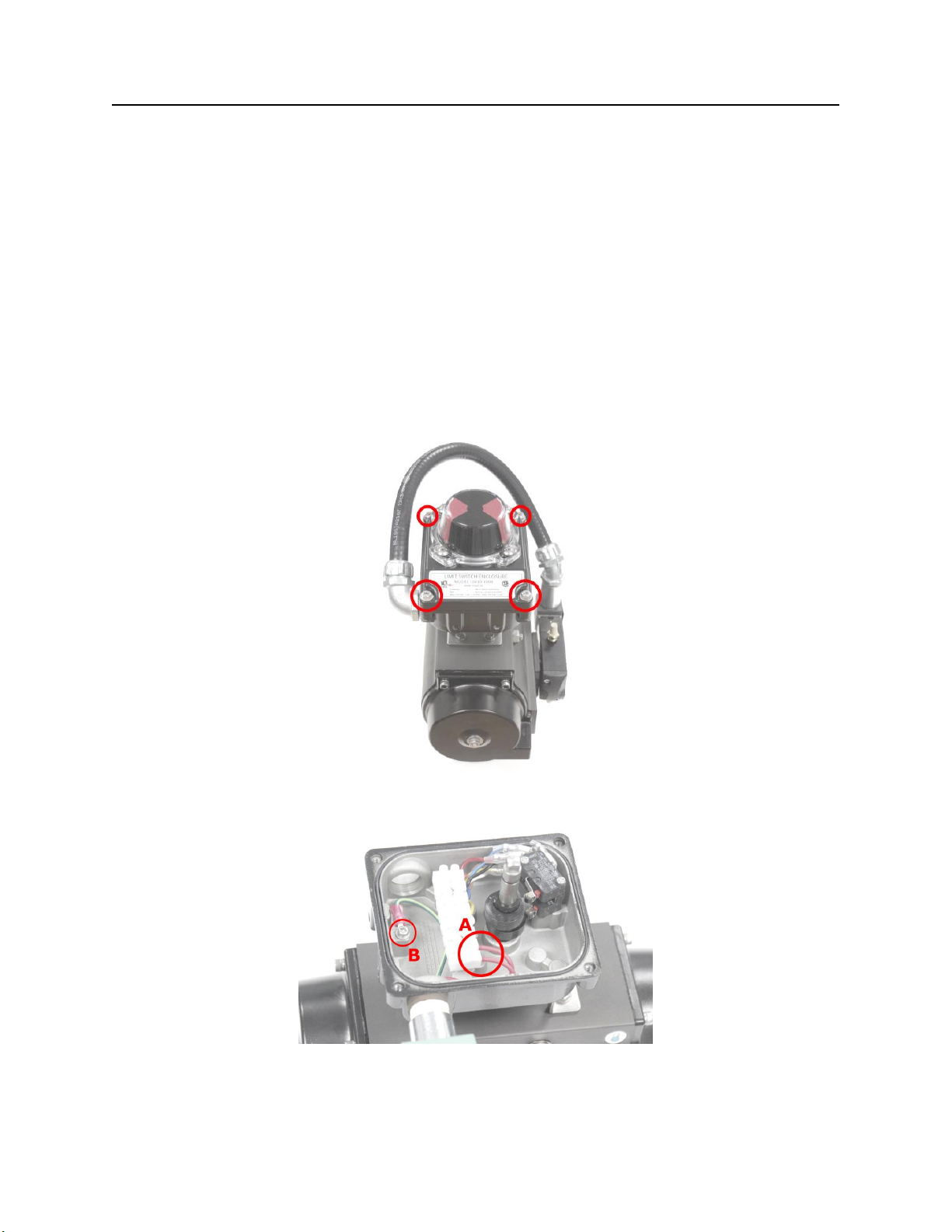
3.5 MAINTENANCE (NAMUR MOUNT SPOOL TYPE SOLENOID) - REPLACING SOLENOID
Caution: following ANY valve maintenance it is required to fully test valve operation and to complete FPS valve
automated valve repair check sheet FP081.0.
Note: for replacement of Parker spool-type solenoids with ASCO poppet type solenoids, refer to FPS instruction
bulletin 9640-1106.
Disassembly:
To remove the solenoid:
1) Ensure valve is in its fail-safe (not actuated) position fully open or closed before disassembly. Pressure trapped
in the valve or actuator if partially stroked could be hazardous.
2) De-pressurize process media and instrument air and turn off electrical power to the valve before attempting
any repair.
3) Remove limit switch cover by loosening four capscrews shown.
4) Disconnect the two power leads A from the limit switch terminal block (terminals 7 and 8), and the ground lead
B from the ground stud.
12
9650 Valve Series
Installation and Maintenance Manual
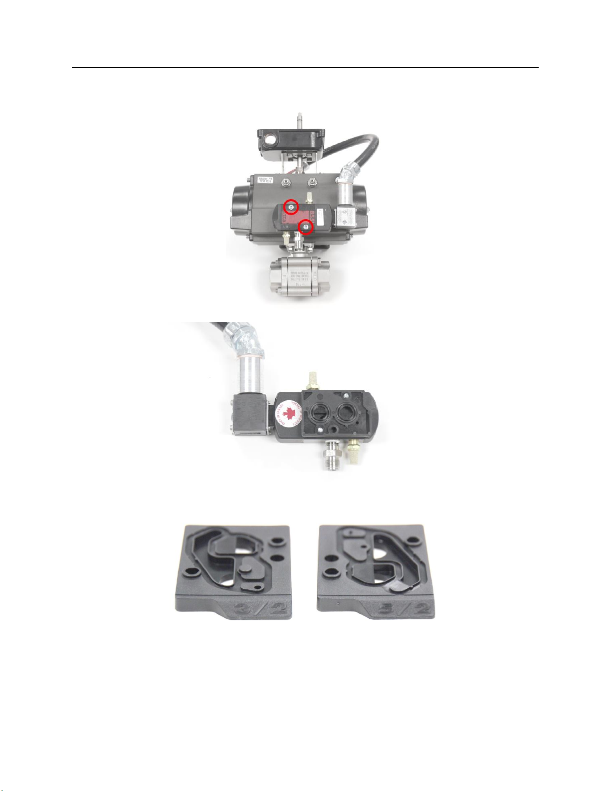
5) Remove the electrical conduit from the limit switch housing leading to the solenoid.
6) Loosen the two capscrews holding the solenoid onto the actuator.
7) Remove the solenoid, taking care not to lose the adapter plate, rubber gasket or two O-rings.
8) Note whether the adapter plate is for 5/2 or 3/2 configuration from the markings.
13
 Loading...