

FPI L234-NG, L234-LP, L234 Owners & Installation Manual
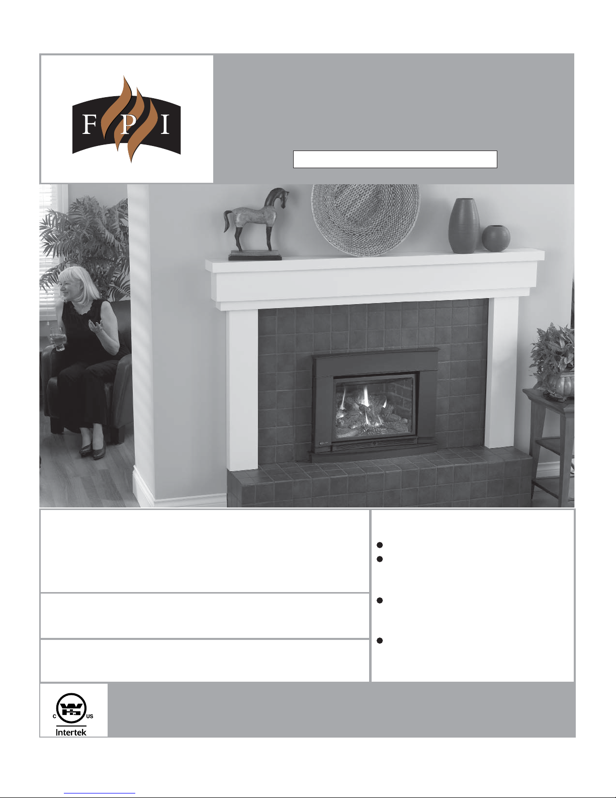
L234 Gas Insert
MODELS: L234-NG Natural Gas L234-LP Propane
Owners & Installation Manual
WARNING:
Improper installation, adjustment, alteration, service or
maintenance can cause injury, property damage, or loss
of life. Refer to this manual. For assistance or additional
information consult an authorized installer, service agency
or the gas supplier.
FOR YOUR SAFETY:
Do not store or use gasoline or other fl ammable vapours and
liquids in the vicinity of this or any other appliance.
Installation and service must be performed by an authorized
installer, service agency or the gas supplier.
Tested by:
Homeowner: Please keep these instructions for future reference.
918-667a
FPI FIREPLACE PRODUCTS INTERNATIONAL LTD. 6988 Venture St., Delta, BC, Canada V4G 1H4
FOR YOUR SAFETY:
What to do if you smell gas:
Do not try to light any appliance
Do not touch any electrical switch:
do not use any phone in your
building.
Immediately call your gas supplier
from a neighbour's phone. Follow
the gas supplier's instructions.
If you cannot reach your gas
supplier, call the fi re department.
Installer: Please complete the details on the back cover
and leave this manual with the homeowner.
06/29/11
REGENCY GAS FIREPLACE INSERT
TO THE NEW OWNER
Congratulations! You are the owner of a state-of-the-art Gas Insert by FPI.
The L234 Direct Vent Gas Insert has been designed to provide you with all the warmth and charm
of a fi replace, at the fl ick of a switch. The L234-NG and L234-LP have been approved by W arnock
Hersey for both safety and effi ciency.
As it also bears our own mark, it promises to provide you with economy, comfort and security for
many trouble free years to follow. Please take a moment now to acquaint yourself with these
instructions and the many features of your FPI Fireplace.
2
Regency® L234 Direct Vent Gas Insert

TABLE OF CONTENTS
SAFETY LABEL
Safety Label...................................................................4
REQUIREMENTS
MA Code - CO Detector.................................................5
UNIT DIMENSIONS
Unit & Faceplate Dimensions .......................................6
INSTALLATION
For Your Safety ..............................................................7
Important Message .......................................................8
Gas Pressure Testing ....................................................8
Specifi cations ................................................................8
Installation Into A Solid Fuel Burning Fireplace .............8
Before You Start ............................................................8
Installation Checklist .....................................................9
Materials Required ........................................................9
Minimum Fireplace Opening..........................................9
Minimum Clearances To Combustibles .......................10
Combustible Mantel ...................................................10
Clearances ..................................................................10
Venting.........................................................................11
Converting from 3" & 3" venting to 3" & 2" ..................12
Vent Restrictor Position ...............................................12
Flue Liner Installation ..................................................13
Gas Connection ..........................................................13
Gas Insert Aeration System .........................................13
Gas Pipe Pressure Testing ..........................................14
SIT Valve Description ..................................................14
Conversion Kit #536-969 from NG to LP .....................15
Optional Brick Panel Installation .................................17
Screen door install/ removal ........................................18
Glass door install/ removal ..........................................18
Contour or Contemporary Faceplate ..........................19
Optional Backing Plate ................................................22
Optional Hearth Trim ...................................................24
Log Set Installation ......................................................25
Wiring Diagrams ..........................................................29
Optional Remote Control ............................................30
Optional Wall Thermostat ...........................................30
Final Check..................................................................30
First Fire ......................................................................31
OPERATING INSTRUCTIONS
Operating Instructions .................................................31
Lighting Procedure ......................................................31
Shutdown Procedure ...................................................31
Copy Of Lighting Instruction Plate ..............................32
Automatic Convection
Fan Operation..............................................................32
Normal Operating Sounds Of Gas Appliances ............32
Maintenance Instructions.............................................33
Log Replacement ........................................................33
Glass Gasket ...............................................................33
General Vent Maintenance .......................................33
Door Glass ..................................................................33
Fan Replacement ........................................................34
Valve Replacement .....................................................36\
PARTS LIST
Main Assembly ............................................................38
Faceplate Assembly ....................................................39
Backing Plate & Hearth Trim Assembly .......................40
WARRANTY
Warranty ......................................................................43
Regency® L234 Direct Vent Gas Insert
33
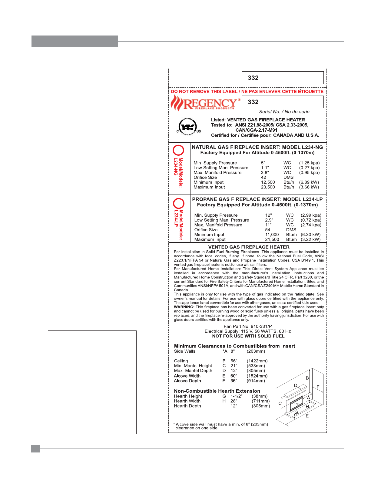
SAFETY LABEL
This is a copy of the labels that accompany each
L234 Gas Insert. We have printed a copy of the
contents here for your review. The safety label
is located on a plate inside the base of the unit
visible when the bottom louver is opened. Ensure
that the safety label is attached to the unit.
NOTE: FPI units are constantly being
improved. Check the label on the unit and
if there is a difference, the label on the unit
is the correct one.
For the State of Massachusetts, installation
and repair must be done by a plumber or
gasfi tter licensed in the Commonwealth of
Massachusetts.
For the State of Massachusetts, fl exible
connectors shall not exceed 36 inches in
length.
For the State of Massachusetts, the appliances individual manual shut-off must be a
t-handle type valve.
The State of Massachusetts requires the
installation of a carbon monoxide alarm in
accordance with NFPA 720 and a CO alarm
with battery back up in the same room where
the gas appliance is installed.
4
Regency® L234 Direct Vent Gas Insert

REQUIREMENTS
MA Code - CO Detector
(for the State of Massachusetts only)
5.08: Modifications to NFPA-54, Chapter 10
(2) Revise 10.8.3 by adding the following additional requirements:
(a) For all side wall horizontally vented gas fueled equipment installed in every dwelling, building or structure used in whole or in part for
residential purposes, including those owned or operated by the Commonwealth and where the side wall exhaust vent termination is less than
seven (7) feet above finished grade in the area of the venting, including but not limited to decks and porches, the following requirements shall
be satisfied:
1. INSTALLATION OF CARBON MONOXIDE DETECTORS. At the time of installation of the side wall horizontal vented gas fueled
equipment, the installing plumber or gasfitter shall observe that a hard wired carbon monoxide detector with an alarm and battery back-up is
installed on the floor level where the gas equipment is to be installed. In addition, the installing plumber or gasfitter shall observe that a battery
operated or hard wired carbon monoxide detector with an alarm is installed on each additional level of the dwelling, building or structure
served by the side wall horizontal vented gas fueled equipment. It shall be the responsibility of the property owner to secure the services of
qualified licensed professionals for the installation of hard wired carbon monoxide detectors
a. In the event that the side wall horizontally vented gas fueled equipment is installed in a crawl space or an attic, the hard wired carbon
monoxide detector with alarm and battery back-up may be installed on the next adjacent floor level.
b. In the event that the requirements of this subdivision can not be met at the time of completion of installation, the owner shall have a period of
thirty (30) days to comply with the above requirements; provided, however, that during said thirty (30) day period, a battery operated carbon
monoxide detector with an alarm shall be installed.
2. APPROVED CARBON MONOXIDE DETECTORS. Each carbon monoxide detector as required in accordance with the above provisions
shall comply with NFPA 720 and be ANSI/UL 2034 listed and IAS certified.
3. SIGNAGE. A metal or plastic identification plate shall be permanently mounted to the exterior of the building at a minimum height of eight
(8) feet above grade directly in line with the exhaust vent terminal for the horizontally vented gas fueled heating appliance or equipment. The
sign shall read, in print size no less than one-half (1/2) inch in size, "GAS VENT DIRECTLY BELOW. KEEP CLEAR OF ALL
OBSTRUCTIONS".
4. INSPECTION. The state or local gas inspector of the side wall horizontally vented gas fueled equipment shall not approve the installation
unless, upon inspection, the inspector observes carbon monoxide detectors and signage installed in accordance with the provisions of 248 CMR
5.08(2)(a)1 through 4.
(b) EXEMPTIONS: The following equipment is exempt from 248 CMR 5.08(2)(a)1 through 4:
1. The equipment listed in Chapter 10 entitled "Equipment Not Required To Be Vented" in the most current edition of NFPA 54 as adopted by
the Board; and
2. Product Approved side wall horizontally vented gas fueled equipment installed in a room or structure separate from the dwelling, building or
structure used in whole or in part for residential purposes.
(c) MANUFACTURER REQUIREMENTS - GAS EQUIPMENT VENTING SYSTEM PROVIDED. When the manufacturer of Product
Approved side wall horizontally vented gas equipment provides a venting system design or venting system components with the equipment, the
instructions provided by the manufacturer for installation of the equipment and the venting system shall include:
1. Detailed instructions for the installation of the venting system design or the venting system components; and
2. A complete parts list for the venting system design or venting system.
(d) MANUFACTURER REQUIREMENTS - GAS EQUIPMENT VENTING SYSTEM NOT PROVIDED. When the manufacturer of a
Product Approved side wall horizontally vented gas fueled equipment does not provide the parts for venting the flue gases, but identifies
"special venting systems", the following requirements shall be satisfied by the manufacturer:
1. The referenced "special venting system" instructions shall be included with the appliance or equipment installation instructions; and
2. The "special venting systems" shall be Product Approved by the Board, and the instructions for that system shall include a parts list and
detailed installation instructions.
(e) A copy of all installation instructions for all Product Approved side wall horizontally vented gas fueled equipment, all venting instructions,
all parts lists for venting instructions, and/or all venting design instructions shall remain with the appliance or equipment at the completion of
the installation.
Regency® L234 Direct Vent Gas Insert
5
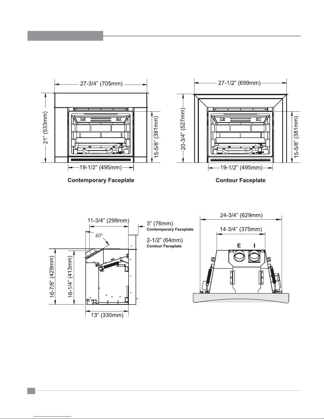
DIMENSIONS
6
Regency® L234 Direct Vent Gas Insert
INSTALLATION
FOR YOUR SAFETY
This appliance requires air for proper combustion.
Always provide adequate combustion and
ventilation air. Follow instructions and information
in CSA B149.1 (in Canada) or the National Fuel Gas
Code ANS Z223.1/NFPA (in the USA), regarding
requirements for combustion and ventilation air.
INSTALLATION AND REPAIR SHOULD
BE DONE BY AN AUTHORIZED
SERVICE PERSON. THE APPLIANCE
SHOULD BE INSPECTED BEFORE
USE AND AT LEAST ANNUALLY BY A
PROFESSIONAL SERVICE PERSON.
MORE FREQUENT CLEANING MAY
BE REQUIRED DUE TO EXCESSIVE
LINT FROM CARPETING, BEDDING
MATERIAL, ETC. IT IS IMPERATIVE THAT
CONTROL COMPARTMENTS, BURNERS
AND CIRCULATING AIR PASSAGEWAYS
OF THE APPLIANCE BE KEPT CLEAN.
DUE TO HIGH TEMPERATURES, THE
APPLIANCE SHOULD BE LOCATED
OUT OF TRAFFIC AND AWAY FROM
FURNITURE AND DRAPERIES.
YOUNG CHILDREN SHOULD BE CAREFULLY SUPERVISED WHEN THEY ARE
IN THE SAME AREA AS THE APPLIANCE. TODDLERS, YOUNG CHILDREN
AND OTHERS MAY BE SUSCEPTIBLE
TO ACCIDENTAL CONTACT BURNS. A
PHYSICAL BARRIERS IS RECOMMENDED IF THERE ARE AT RISK INDIVIDUAL
IN THE HOUSE. TO RESTRICT ACCESS
TO A FIREPLACE OR STOVE, INSTALL
AN ADJUSTABLE SAFETY GATE TO
KEEP TODDLERS, YOUNG CHILDREN
AND OTHER AT RISK INDIVIDUALS OUT
OF THE ROOM AND AWAY FROM HOT
SURFACES.
CLOTHING OR OTHER FLAMMABLE
MATERIAL SHOULD NOT BE PLACED
ON OR NEAR THE APPLIANCE.
WARNING: FAILURE TO INSTALL THIS
APPLIANCE CORRECTLY WILL VOID
YOUR WARRANTY AND MAY CAUSE A
SERIOUS HOUSE FIRE.
CHILDREN AND ADULTS SHOULD BE
ALERTED TO THE HAZARDS OF HIGH
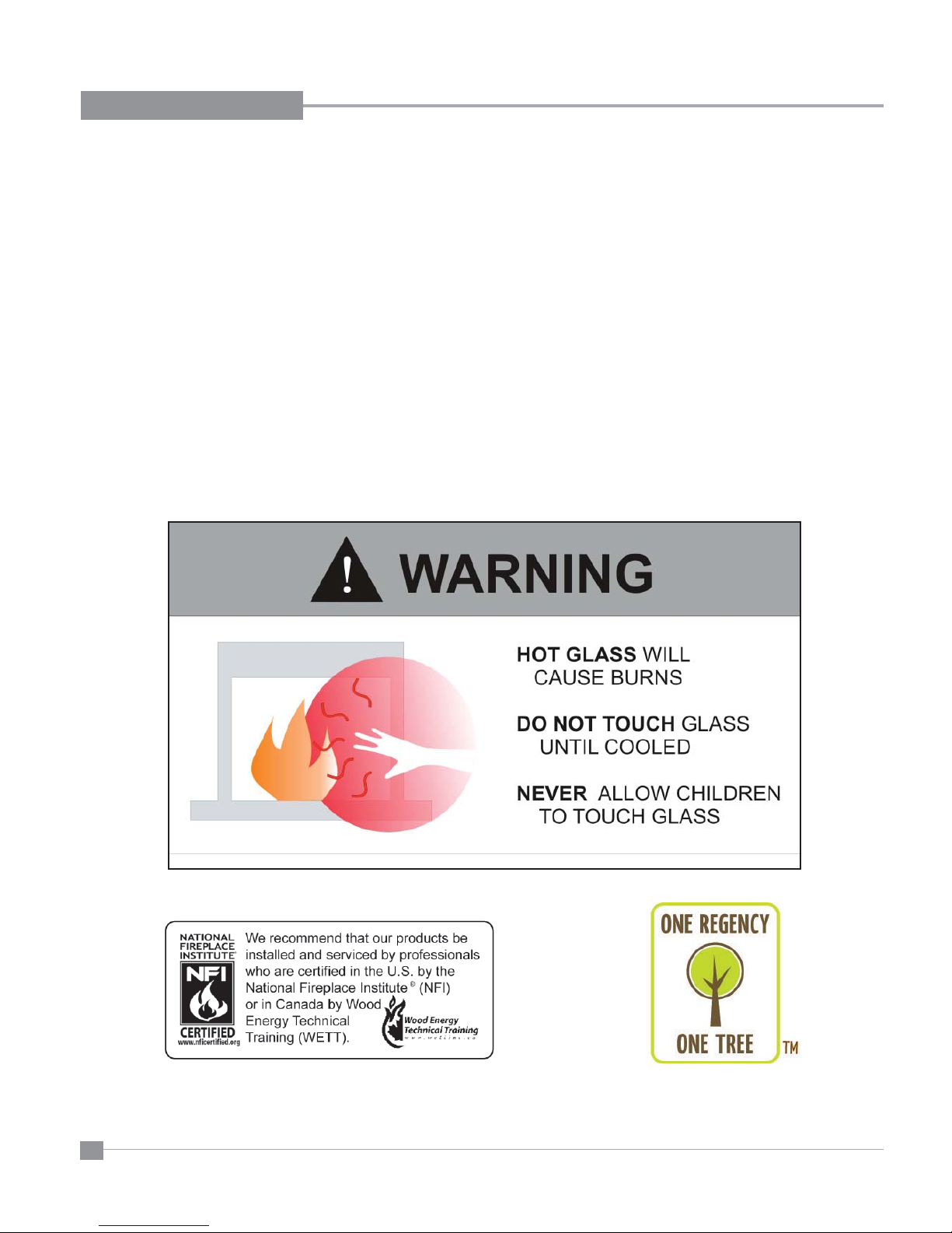
SURFACE TEMPERATURES, ESPECIALLY THE FIREPLACE GLASS, AND
SHOULD STAY AWAY TO AVOID BURNS
OR CLOTHING IGNITION.
Regency® L234 Direct Vent Gas Insert
7

INSTALLATION
IMPORTANT MESSAGE
SAVE THESE
INSTRUCTIONS
The FPI Direct Vent Gas Insert must be installed in
accordance with these instructions. Carefully read
all the instructions in this manual fi rst. Consult the
building authority having jurisdiction to determine
the need for a permit prior to starting the installation.
NOTE: Failure to follow the instructions could cause
a malfunction of the heater which could result in
death, serious bodily injury, and/or property damage.
Failure to follow these instructions may also void
your fi re insurance and/or warranty.
GAS PRESSURE
TESTING
The appliance must be isolated from the gas supply
piping system by closing its individual manual shut off
valve during any pressure testing of the gas supply
piping system at test pressures equal to or less than
1/2 psig. (3.45 kPa).
SPECIFICATIONS
At pressures over 1/2 psig, the pipe to the unit must
be disconnected.
Gas Input Capacity:
Natural Gas 23,500 Btu/h
Propane 21,500 Btu/h
Min. Input:
Natural Gas 12,500 Btu/h
Propane 11,000 Btu/h
Fuels: Approved for use with both natural gas,
and propane. Approved as is for use at 0' to 4,500'
(0-1370m).
Electrical: 120V A.C. system.
Circulation Fan: Variable speed, 127 CFM.
Log Set: Ceramic fi bre, 6 per set.
Vent System: 3" co-linear aluminum fl ex
or 2" intake with 3" exhaust.
INSTALLATION INTO A
SOLID FUEL BURNING
FIREPLACE OR
FACTORY BUILT
FIREPLACE
The L234 Gas Inserts have been tested and
approved to be vented into any masonry fi replace
or approved solid fuel burning factory built fi replace
that will allow the insert to physically fi t into the
fi rebox. Refer to the "Minimum Fireplace Opening"
section.
If the factory built fi replace* height is too low
for your Insert, you may remove the smoke
baffl e plate and damper from the factory built
fi replace as long as these items are saved and
are reinstalled in the event that the Insert is
removed. NOTE: Any alterations made to the
listed solid fuel burning factory built fi replace
may void the listing of the fi replace. Cutting
any sheet-metal parts of the fi replace, in which
the gas fi replace insert is to be installed, is
prohibited.
If the factory-built fireplace has no gas
access hole(s) provided, an access hole of
1.5" (37.5mm) or less may be drilled through
the lower sides or bottom of the fi rebox in a
proper workmanship like manner. This access
hole must be plugged with non-combustible
insulation after the gas supply line has been
installed.
The fi replace and fi replace chimney must
be clean and in good working order and
constructed of non-combustible materials and
chimney cleanouts must fi t properly. Refractory,
glass doors, screen rails, screen mesh, and
log grates can be removed from the fi replace
before installing the gas fi replace insert. Smoke
shelves, shields and baffl es may be removed if
attached by mechanical fasteners. A tight seal
between the gas fi replace insert fl ue collar and
the fi replace chimney must be made to prevent
heat loss.
*Check with your local inspector before commencing
with this installation.
Installer must mechanically attach the supplied
label to the inside of the fi rebox of the fi replace
into which the gas fi replace insert is installed.
BEFORE YOU ST ART
Safe installation and operation of this appliance
requires common sense, however, we are required
by the Canadian Safety Standards and ANSI
Standards to make you aware of the following:
General Safety Information
1) The appliance installation must conform
with local codes or in the absence of local
codes, with CAN/CSA B149.1 (in Canada)
or the National Fuel Gas Code ANSI Z223.1
NFPA 54 in the U.S.A. This appliance should
be installed by a qualifi ed gas fi tter technician
only.
2) Installation and repair should be done by a
qualifi ed service person.
3) The appliance should be inspected before
use and at least annually by a professional
service person. More frequent cleaning
may be required due to excessive lint from
carpeting, bedding material, animal hair, etc.
It is imperative that control compartments,
burners and circulating air passageways of
the appliance be kept clean.
4) See general construction and assembly
instructions. This appliance may only be
installed in a vented, noncombustible fi replace.
5) This appliance is Listed for bedroom installations
when used with a Listed Millivolt Thermostat.
Some areas may have further requirements,
check local codes before installation.
6) Always connect this appliance to a vent system
vent that is run (or routed) to the outside of the
building envelope. Never vent to another room
or inside a building. Make sure that the vent
is properly sized and is of adequate height to
provide the proper draft.
7) Inspect the venting system annually for blockage
and any signs of deterioration.
8) Any glass removed for servicing must be
replaced prior to operating the appliance.
9) WARNING: Failure to position the parts in
accordance with the diagrams in this manual
or failure to use only parts specifi cally
approved with this appliance may result in
property damage or personal injury.
8
"WARNING: This fi replace has been converted
for use with a gas fi replace insert only and
cannot be used for burning wood or solid fuels
unless all original parts have been replaced,
and the fi replace re-approved by the authority
having jurisdiction."
10) To prevent injury, do not allow anyone who is
unfamiliar with the operation to use the fi replace.
Regency® L234 Direct Vent Gas Insert
INSTALLATION
aaaaa
aaaaa
aaaaa
aaaaa
aaaaa
aaaaa
aaaaa
aaaaa
aaaaa
aaaaa
aaaaa
aaaaa
aaaaa
aaaaa
aaaaa
aaaaa
aaaaa
aaaaa
aaaaa
aaaaa
aaaaa
aaaaa
aaaaa
aaaaa
aaaaa
aaaaa
aaaaa
aaaaa
aaaaa
aaaaa
aaaaa
aaaaa
aaaaa
aaaaa
aaaaa
aaaaaaaaaa
aaaaaaaaaa
aaaaaaaaaa
aaaaaaaaaa
aaaaaaaaaa
aaaaaaaaaa
11) Due to high temperatures, the appliance
should be located out of high traffi c areas
and away from furniture and draperies.
Children and adults should be alerted to
the hazards of high surface temperatures,
especially the fi replace glass, and should
stay away to avoid burns or clothing
ignition. Y oung children should be carefully
supervised when they are in the same
room as the appliance. Clothing or other
fl ammable material should not be placed
on or near the appliance.
Emissions from burning wood or gas could
contain chemicals known to the State of
California to cause cancer, birth defects or
other reproductive harm.
INSTALLATION
CHECKLIST
Before installing vent system ensure that the
damper plate is open and secure to prevent the
damper plate from falling down and crushing
the liner.
The FPI Gas Insert is installed as listed
below.
1) Check all clearances to combustibles.
Refer to the following sections where
applicable:
a. Minimum Clearances to Combustibles.
b. Combustible Mantel Clearances
c. Mantel Clearances
2) Make the gas connection. Refer to the "Gas
Connection" section.
3) Install the 3" x 3" or 3" x 2" fl ue liner to the
sliding connector plate. Refer to the "Flue
Liner Installation" section.
4) Slide the unit half way into the fi replace.
5) Pull the vent connector plate through the
tapered brackets and fasten to the front
plate. Refer to the "Flue Liner Installation"
section.
6) Slide the unit fully into the fi replace.
7) Test gas pressure, refer to the "Gas Pipe
Pressure Testing" section. Check aeration
system, refer to "Gas Insert Aeration
Systems" section.
Regency® L234 Direct Vent Gas Insert
8) Install standard and optional features.
Refer to the following sections where
applicable:
a. Brick Panels
b. Log Installation
c. Faceplate
d. Hearth Trim
e. Backing Plate
f. Remote Control (brick panels are
mandatory with remote control option)
g. Wall Thermostat
9) Final check. Refer to the "Final Check"
section. Before leaving this unit with the
customer, the installer must ensure that the
appliance is fi ring correctly. This includes:
a) Clocking the appliance to ensure the
correct fi ring rate.
b) Adjusting the primary air, if required,
to ensure that the fl ame does not
carbon. Refer to the "Gas Insert
Aeration System" section.
c) Ensuring that the appliance is venting
correctly.
MATERIALS
REQUIRED
No electrical power supply is required for the gas
control to operate. A 120 V olt AC power cord is
hooked up to the fan. Plug the 3 wire cord into
a suitable receptacle. Do not cut the ground
terminal off under any circumstances. When
connected with 120 volts, the appliance must
be electrically grounded in accordance with
local codes, current version of the Canadian
Electrical Code CSA C22.1 (in Canada) or in
the absence of local codes, with the National
Electrical Code ANSI/NFPA 70.
WARNING:
Electrical Grounding Instructions
This appliance is equipped with
a three pronged (grounding) plug
for your protection against shock
hazard and should be plugged
directly into a properly grounded
three-prong receptacle. Do not cut
or remove the grounding prong
from this plug.
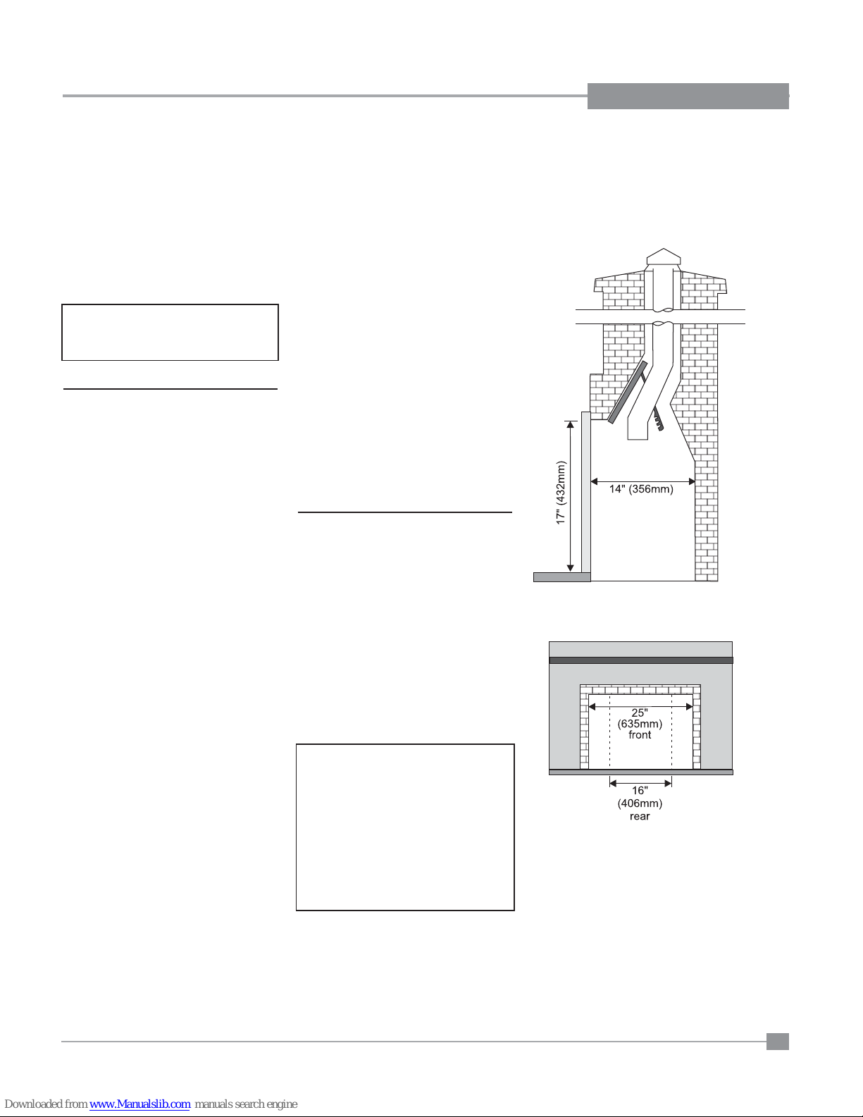
MINIMUM FIREPLACE
OPENING
The minimum fi replace opening for the L234
gas fi replace insert is shown in the following
diagrams:
9
INSTALLATION
Faceplate
12” Min.
Hearth
Mantel
C
12" Max.
D
Existing or
Non-Combustible Hearth
To p o f
Door Frame
G
Faceplate
Combustible
Flooring
Mantel
C
12" Max.
D
To p o f
Door Frame
4” min
MINIMUM CLEARANCES TO
COMBUSTIBLES
Unless otherwise stated the clearances listed below are Minimum distances
to combustible materials. Please Note: A major cause of chimney
related fi res is due to a failure to maintain required clearances (air
space) to combustible materials. It is of the greatest importance
that this insert and vent system be installed only in accordance with
these instructions.
Side Walls A 8" (203 mm)*
Ceiling B 56" (1422 mm)
Min. Mantel Height C 21" (533 mm) see Diagram 1
Max. Mantel Depth D 12" (305 mm)
Alcove Width E 60" (1524 mm)
Alcove Depth F 36" (914 mm)
Hearth Height G 1-1/2" (38 mm)
Hearth Width H 28" (686 mm)
Hearth Depth I 12" (305 mm)
* Alcove side wall must have a min. of 8" clearance.
see Diagram 1
COMBUSTIBLE MANTEL
CLEARANCES
Because of the extreme heat this fi replace emits, the mantel clear-
ances are critical. Combustible mantel clearances from top of door frame
are shown in the diagram below. Mantel may be installed anywhere in the
shaded area or higher.
Note: A non-combustible mantel may be installed at a lower
height.
Note: Ensure the paint that is used on the mantel and the facing is
“heat resistant” or the paint may discolour.
INSTALLATION WITH NON-COM-
BUSTIBLE HEARTH IN FRONT
10
Diagram 1
INSTALLATION WITH COMBUSTIBLE
FLOORING IN FRONT
No hearth required if the unit
is raised 4" (102mm) or more.
Regency® L234 Direct Vent Gas Insert
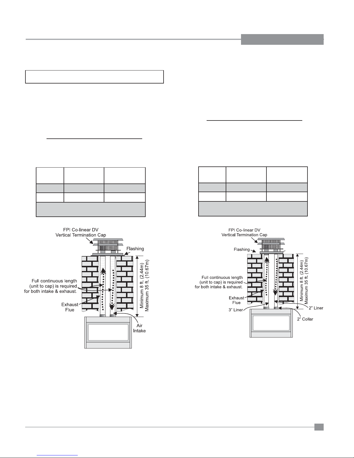
VENTING
INSTALLATION
THE APPLIANCE MUST NOT BE CONNECTED TO A CHIMNEY
FLUE SERVING A SEPARATE SOLID FUEL BURNING APPLIANCE.
This appliance is designed to be attached to two 3" (76mm) co-linear
aluminium fl ex running the full length of the chimney. The fl ue length
must be a minimum length of 8' (2.44m) and a maximum of 35' (10.7m).
Periodically check that the vent is unrestricted.
Masonry chimneys may take various contours which the fl exible liner will
accommodate. However, keep the fl exible liner as straight as possible,
avoid unnecessary bending.
INSTALLATION WITH 3" & 3" LINERS
Part # Description
948-305 3" Flex - 35 ft. (intake & exhaust)
946-529 FPI Co-linear DV Vertical Termination Cap & Flashing
Vent Run
8' to 20' 1" 3/16"
20' to 35' 3/4" 3/16"
NOTE: See instructions in the "Vent Restrictor Positon"
section on positioning of the vent restrictor.
Vent Restrictor
Position
Burner Aeration
Setting
The L234 is also approved for use with a 2" liner for air intake and a 3" liner
for exhaust. This would be suitable for a Class A wood burning chimney
with a minimum 6" round fl ue.
The chimney must be lined with one 2" diameter liner for intake and one
3" diameter liner for exhaust. The minimum vent length is 8' and maximum
is 35'.
INSTALLATION WITH 3" & 2" LINERS
Part # Description
948-305 3" Flex - 35 ft. (exhaust)
948-316 2" Flex - 35 ft. (intake)
946-582 FPI Co-linear DV Vertical Termination Cap, Flashing &
2" Collar
Vent Run
8' to 20' 1" 3/16"
20' to 35' 1" 1/8"
NOTE: See instructions in the "Vent Restrictor Positon"
section on positioning of the vent restrictor.
Vent Restrictor
Position
Burner Aeration
Setting
Alternative Approved Venting Components*
46dva-vc Vertical Termination Cap
46dva-VCH High Wind Cap
923GK 3" Co-linear Adaptor with fl ashing
In areas of consistently high winds, we recommend using the Simpson
Dura-Vent System (923GK adapter and 991 high-wind cap).
The Air Intake pipe must be attached to the inlet air collar of the termination
cap.
*NOTE: Simpson Duravent can only be used with 3" and 3" liners.
Regency® L234 Direct Vent Gas Insert
11
INSTALLATION
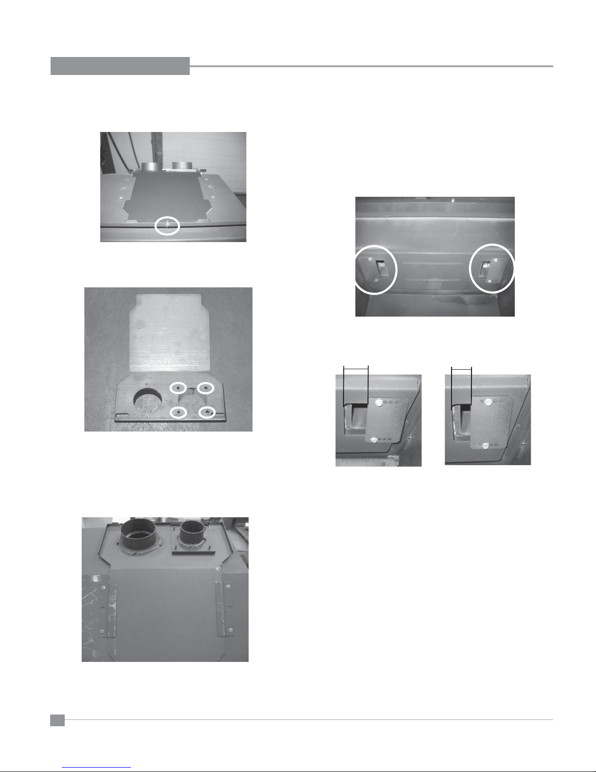
CONVERTING FROM 3" & 3" VENTING TO 3" & 2"
1) Remove the top plate from the unit by undoing the screw at the front
of the fi rebox and slide out towards the back of the unit.
2) Remove the 3" collar from the top plate by undoing the 4 screws.
NOTE: The screws are secured from the underside of the top plate.
VENT RESTRICTOR POSITION
The Vent Restrictor plate is located on the inside top of the fi rebox.
To change the vent restrictor position, refer to the instructions below;
1) Remove the glass door.
2) Remove brick panels if installed.
3) Remove the 4 screws that hold the vent restrictor plate in place.
4) Adjust the vent restrictor plate to the required vent restrictor
position.
1"
›
‹
3/4"
›
‹
Underside of Top Plate
3) Secure the 2" collar to the top plate using 4 screws in place of the 3"
collar.
4) Re-install the top plate to the unit.
Top Plate with 2" Collar shown on Unit
12
Factory Set at 1"
5) Once the vent restrictor plate is in the required position, secure using
the 4 screws removed from step 3.
6) Re-install brick panels if removed.
7) Re-install glass door.
Regency® L234 Direct Vent Gas Insert
Adjusted to 3/4"
INSTALLATION
FLUE LINER
INSTALLATION
1) Cut the fl ex liner as required.
2) Mark the end of one liner with an "E" to indicate Exhaust.
3) Connect the other end of the above liner to the exhaust side of the
termination cap, seal connection with high temperature silicone.
Secure with gear clamp or screws.
4) Connect the 2nd liner to the inlet side of the cap, seal connection
with high temperature silicone. Secure with gear clamp or screws.
5) Install fl ashing.
6) Insert both liners into chimney, passing through the damper open-
ing.
7) Install termination cap.
8) Connect the marked end of the liner to the exhaust collar of the
vent connector plate marked with an "E", seal connection with high
temperature silicone. Secure with gear clamp or screws.
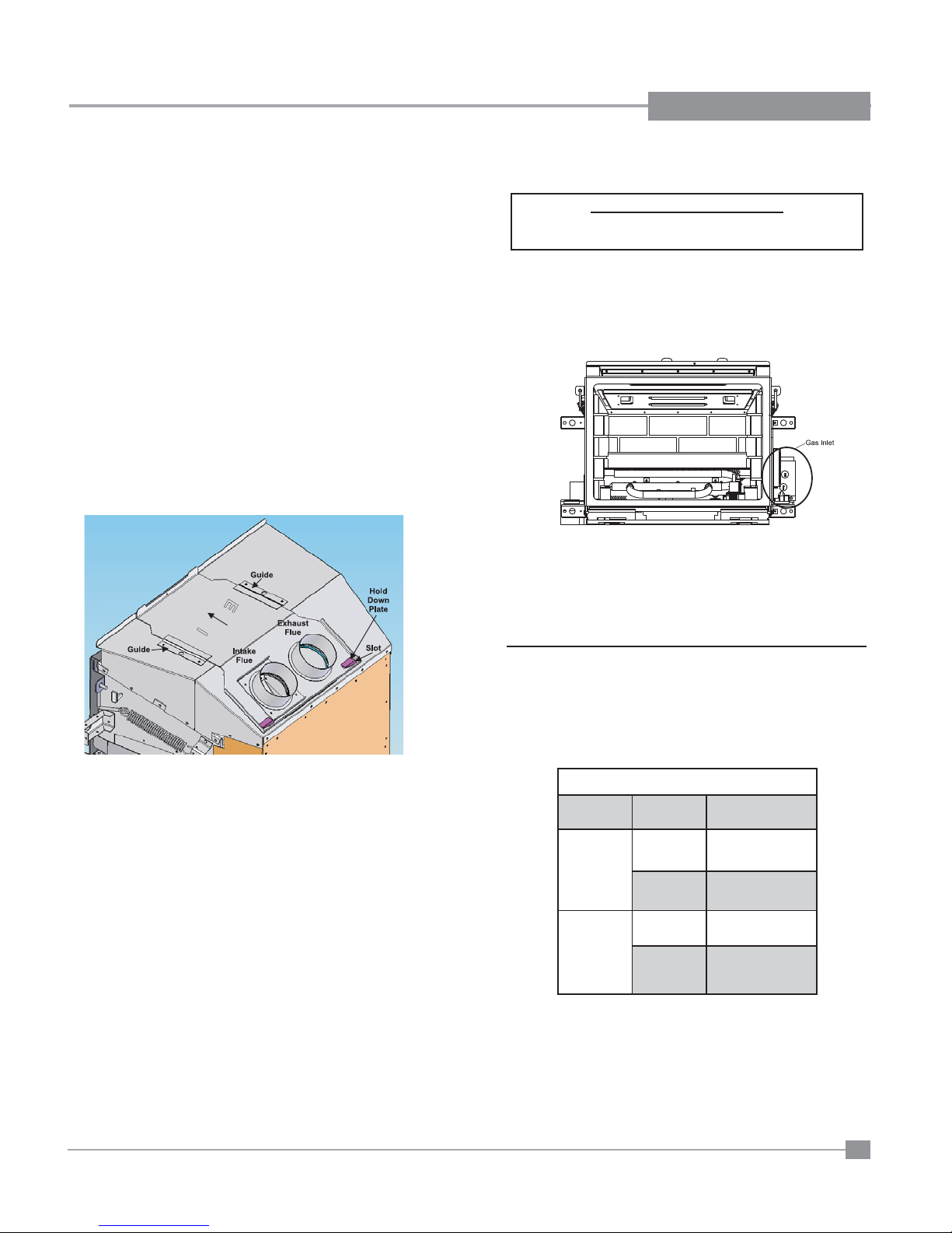
GAS CONNECTION
GAS CONNECTION WARNING:
Only persons licensed to work with gas piping may
make the necessary gas connections to this appliance.
1) When the appliance is to be installed into either an existing masonry
chimney system or factory built fi replace, thoroughly clean the
chimney before installation.
2) A 3/8" NPT gas supply pipe must be brought near the inlet hole.
The valve inlet is on the right side of the unit.
3) Locate the center point where the vent will pass through the chimney
above the appliance. Move the appliance into the exact location
where it is to be installed. Ensure that the Insert is level.
NOTE: This unit is equipped with a heat sensor thermodisc which
will prevent the blower from operating until the unit reaches the
correct temperature.
9) Connect the 2nd liner to the intake collar, seal connection with high
temperature silicone. Secure with gear clamp or screws.
10) Align vent connector plate with guides on unit.
11) Slide unit into masonry opening, while ensuring that the slots at the
rear of the connector plate mates up with the hold down plate on
the unit.
12) Secure with screw.
NOTE:
1) Final gas connection should be made after unit is in place to avoid
damage to the liner when pushing the unit into position.
2) Mill-pac may be used instead of high tempture silicone and screws
may be used instead of gear clamps at connections of liner to inlet
and vent collars.
GAS INSERT
AERATION SYSTEM
The burner aeration is factory set but may need adjusting due to either
the local gas supply or altitude. Open the air shutter for a blue fl ame
or close for a more yellow fl ame.
Minimum Air Shutter Openings
Vent Run
8' to 20'
3" x 3"
20' to 35'
8' to 20'
3" x 2"
20' to 35'
CAUTION: Carbon will be produced if the air shutter is closed
too much.
Note: Any damage due to carboning resulting from improperly setting
the aeration controls is NOT covered under warranty.
Note: Aeration Adjustment should only be performed by an authorized
FPI Installer at the time of installation or service.
Burner Aeration
Setting
NG: 3/16"
LP: 3/16"
NG: 3/16"
LP: 3/16"
NG: 3/16"
LP: 3/16"
NG: 1/8"
LP: 1/8"
Regency® L234 Direct Vent Gas Insert
13
INSTALLATION
1
2
3
4
5
6
IN OUT
GAS PIPE
PRESSURE TESTING
The appliance must be isolated from the gas supply piping system by closing
its individual manual shut-off valve during any pressure testing of the gas
supply piping system at test pressures equal to or less than 1/2 psig.
(3.45 kPa). Disconnect piping from valve at pressures over 1/2 psig.
The manifold pressure is controlled by a regulator built into the gas control,
and should be checked at the pressure test point.
NOTE: To properly check gas pressure, both inlet and manifold
pressures should be checked using the valve pressure ports
on the valve.
1) Make sure the valve is in the "OFF" position.
2) Loosen the "IN" and/or "OUT" pressure tap(s), turning counterclockwise
with a 1/8" wide fl at screwdriver.
3) Attach manometer to "IN" and/or "OUT" pressure tap(s) using a 5/16"
ID hose.
4) Light the pilot and turn the valve to "ON" position.
5) The pressure check should be carried out with the unit burning and
the setting should be within the limits specifi ed on the safety label.
6) When fi nished reading manometer, turn off the gas valve, disconnect
the hose and tighten the screw (clockwise) with a 1/8" fl at screwdriver .
Note: Screw should be snug, but do not over tighten.
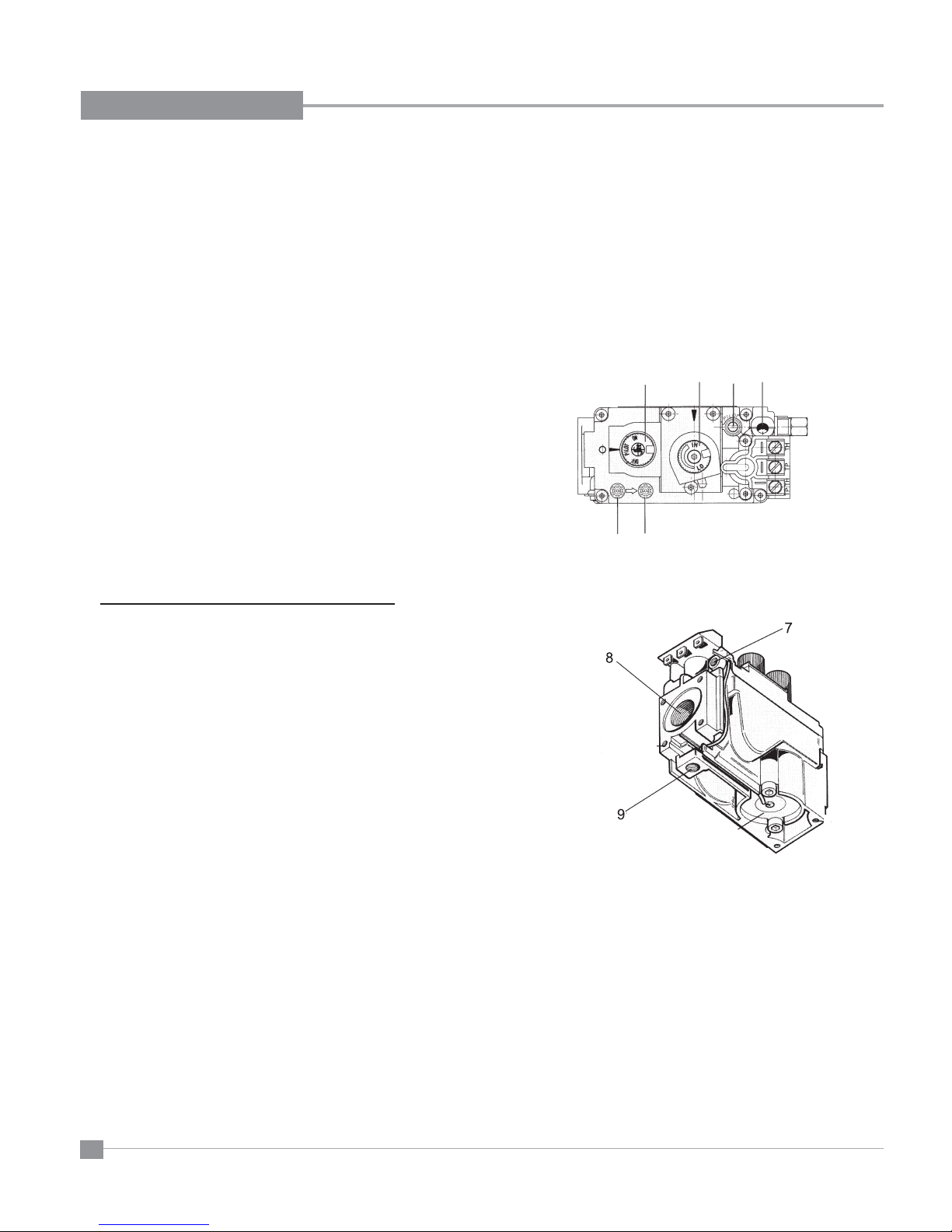
SIT VALVE DESCRIPTION
1) Gas on/off knob
2) Manual high/low adjustment
3) Pilot Adjustment
4) Thermocouple Connection - option
5) Manifold (Outlet) Pressure Tap
6) Inlet Pressure Tap
7) Pilot Outlet
8) Main Gas Outlet
9) Alternative TC Connection Point
14
Regency® L234 Direct Vent Gas Insert
 Loading...