

Page 1
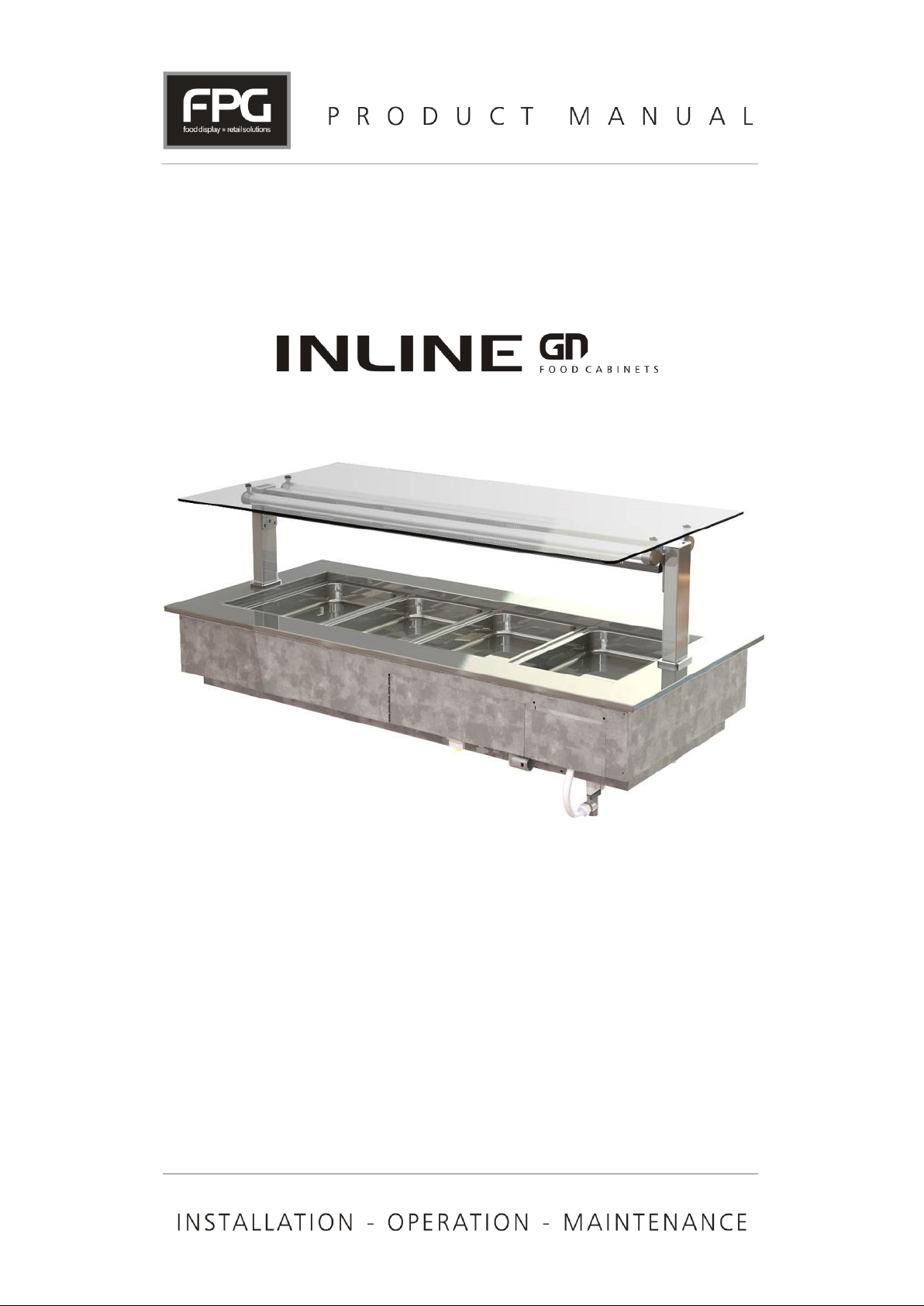
Inline GN Series
Heated Well
Page 2

Copyright © February 2016 Future Products Group Limited.
All rights reserved.
No part of this publication may be reproduced, stored in a retrieval
system, or transmitted in any form or by any means, electronic,
mechanical, photocopying, recording or otherwise, without the prior
written permission of Future Products Group Ltd.
Note: Cover Picture shows well fitted with optional gantry.
Part No.21966 Rev. M February 2016 - 2 - Heated Well GN Series
Page 3

Table of Contents
INTRODUCTION ................................................................................................................. 6
Welcome ........................................................................................................................................................... 6
Future Products Group (FPG) .................................................................................................................... 6
Guidance and Help ..................................................................................................................................... 6
Warranty ........................................................................................................................................................... 6
Warranty Period .......................................................................................................................................... 6
Liability Exceptions ..................................................................................................................................... 7
Specific Exclusions ..................................................................................................................................... 7
Assessment ................................................................................................................................................ 7
Time Limit ................................................................................................................................................... 7
Caution ....................................................................................................................................................... 7
OPERATION ....................................................................................................................... 8
Configuration ................................................................................................................................................... 8
Mechanical Features .................................................................................................................................. 8
Operational Modes ..................................................................................................................................... 8
Operating Temperature .............................................................................................................................. 8
Overflow and Drain ..................................................................................................................................... 8
Auto-fill ........................................................................................................................................................ 8
Optional Lighting ......................................................................................................................................... 8
Controls ............................................................................................................................................................ 9
Control Panel .............................................................................................................................................. 9
Temperature ............................................................................................................................................... 9
Operating Mode .......................................................................................................................................... 9
On/Off Switch ............................................................................................................................................. 9
Indicator Lamps .......................................................................................................................................... 9
Operating Mode ............................................................................................................................................. 10
Choice of Mode ........................................................................................................................................ 10
Dry Mode .................................................................................................................................................. 10
Steam Mode ............................................................................................................................................. 10
Wet Mode ................................................................................................................................................. 10
Temperature Settings .................................................................................................................................... 11
Setting Guide ............................................................................................................................................ 11
Dry Mode Temperature ............................................................................................................................ 11
Steam Mode Temperature ....................................................................................................................... 11
Wet Mode Temperature ........................................................................................................................... 11
Storage and Display Basics ......................................................................................................................... 11
Food Temperature .................................................................................................................................... 11
Display Time ............................................................................................................................................. 11
Unsuitable Food Type .............................................................................................................................. 11
Preparation ..................................................................................................................................................... 12
Power Supply ........................................................................................................................................... 12
Decide on the Required Mode .................................................................................................................. 12
Caution Turn on Lights If fitted ................................................................................................................ 12
Pre-heat the Well ...................................................................................................................................... 12
Fumes and Odours ................................................................................................................................... 12
Load Food ................................................................................................................................................ 12
Monitor Temperatures .............................................................................................................................. 12
Monitor Water Level ................................................................................................................................. 12
IN-GNH03/4/5/6/8 - 3 - © Future Products Group
Page 4

TROUBLE SHOOTING ..................................................................................................... 13
CLEANING ........................................................................................................................ 14
Cautions ......................................................................................................................................................... 14
Power ....................................................................................................................................................... 14
Water ........................................................................................................................................................ 14
Exterior ........................................................................................................................................................... 14
Metal Surfaces .......................................................................................................................................... 14
Glass ........................................................................................................................................................ 14
Interior............................................................................................................................................................. 15
Cabinet Well ............................................................................................................................................. 15
Stainless Steel Surfaces .......................................................................................................................... 15
Routines ......................................................................................................................................................... 15
Schedules ................................................................................................................................................. 15
Inspection ................................................................................................................................................. 15
Correction ................................................................................................................................................. 15
INSTALLATION ................................................................................................................ 16
Regulations .................................................................................................................................................... 16
Compliance with Local Requirements ...................................................................................................... 16
Setting Up ....................................................................................................................................................... 16
Unpacking ................................................................................................................................................. 16
Site Preparation ........................................................................................................................................ 16
Well Assembly Preparation ...................................................................................................................... 16
Grounding ................................................................................................................................................. 16
Power Supply ........................................................................................................................................... 17
Isolation .................................................................................................................................................... 17
Protection ................................................................................................................................................. 17
Water Supply ............................................................................................................................................ 17
Location .......................................................................................................................................................... 17
Ventilation ................................................................................................................................................. 17
Access ...................................................................................................................................................... 17
Fumes and Odours ................................................................................................................................... 17
SERVICING ....................................................................................................................... 18
Control Gear ................................................................................................................................................... 18
Location .................................................................................................................................................... 18
Heating ............................................................................................................................................................ 18
Caution ..................................................................................................................................................... 18
Element Replacement .............................................................................................................................. 18
Test ........................................................................................................................................................... 18
Temperature Probe .................................................................................................................................. 19
Over Temperature Cut Out ....................................................................................................................... 19
Part No.21966 Rev. M February 2016 - 4 - Heated Well GN Series
Page 5

Water Level Control ....................................................................................................................................... 19
Indicator Module ....................................................................................................................................... 19
Water Sensing Probes ............................................................................................................................. 19
Auto-fill ...................................................................................................................................................... 19
Mains Lead ..................................................................................................................................................... 19
Lead Replacement ................................................................................................................................... 19
SPECIFICATIONS ............................................................................................................. 20
Mechanical ..................................................................................................................................................... 20
Electrical ......................................................................................................................................................... 20
Compliance .................................................................................................................................................... 21
Safety Aspects .......................................................................................................................................... 21
Improvements ................................................................................................................................................ 21
Ongoing Development .............................................................................................................................. 21
ELECTRICAL CIRCUIT DIAGRAMS ................................ ................................ ................ 22
Model: IN-GNH03 ..................................................................................................................................... 22
Model: IN-GNH03 Auto-fill ........................................................................................................................ 22
Model: IN-GNH04 ..................................................................................................................................... 23
Model: IN-GNH04 Auto-fill ........................................................................................................................ 23
Model: IN-GNH05 ..................................................................................................................................... 24
Model: IN-GNH05 Auto-fill ........................................................................................................................ 24
Model: IN-GNH06 ..................................................................................................................................... 25
Model: IN-GNH06 Auto-fill ........................................................................................................................ 25
Model: IN-GNH08 Auto-fill ........................................................................................................................ 26
SPARE PARTS ................................................................................................................. 27
Assembly Serial Number .......................................................................................................................... 27
MECHANICAL DRAWINGS .............................................................................................. 28
Dimensions .................................................................................................................................................... 28
IN-GNH03 to GNH06 ................................................................................................................................ 28
.................................................................................................................................................................. 28
IN-GNH08 ................................................................................................................................................. 29
Bench Cut-outs .............................................................................................................................................. 30
Over Mount Installation ............................................................................................................................ 30
Flush Mount Installation ........................................................................................................................... 31
Under Mount Installation .......................................................................................................................... 32
Auto-fill Components .................................................................................................................................... 33
IN-GNH03/4/5/6/8 - 5 - © Future Products Group
Page 6
Future
Products
Group (FPG)
Welcome to the world of FPG! Our products are designed and engineered to
give you the optimal performance that you deserve with innovative visual
merchandising appeal.
We are confident that you will be delighted with your state of the art inline food
service cabinet, and that it will become a valued appliance.
Guidance and
Help
Any new appliance can seem very complex and confusing at first glance. To
ensure you receive the utmost benefit from your new inline cabinet, there are
two things you can do.
Before operating the cabinet, please read the instruction book carefully and
follow its recommendations. The time taken will be well spent. These
instructions both general and technical tell you how to install, operate and
look after your inline food service cabinet so that you can receive the full
benefits that this cabinet has to offer.
These instructions cannot, however, cover all eventualities. If you are
unsure of any aspect of the installation, instructions or performance of your
cabinet, contact your dealer promptly or contact us via email to
[email protected].
Warranty
Period
Future Products Group Limited warrants, to the original purchaser of an FPG
manufactured food service cabinet that for ONE YEAR (12 months), from the
date of purchase, any defect in workmanship or material resulting in the product
malfunctioning while under correct use will be rectified.
Liability under this warranty is limited to replacing or repairing a part, without
charge.
Welcome
DROP-IN HEATED WELL ASSEMBLIES
INTRODUCTION
-
INTRODUCTION
Warranty
DROP-IN HEATED WELL ASSEMBLIES
Part No.21966 Rev. M February 2016 - 6 - Heated Well GN Series
-
INTRODUCTION
Continued on next page
Page 7
Liability
Exceptions
Liability under this warranty does not include:
Any loss, or damage or expenses directly or indirectly arising from use or
inability to use the product or from any other cause.
Any part of the cabinet which has been subject to misuse, neglect,
alteration, incorrect installation, accident, or damage caused by
transportation, use of abrasive or caustic chemicals, flooding, fire or acts of
God.
Any damage or malfunction resulting from the use of non-FPG supplied
spare parts.
Specific
Exclusions
The following are specifically excluded from warranty:
Breakage of glass or plastic components or the replacement of lamps,
fluorescent tubes or gaskets.
Failure resulting from incorrect assembly after cleaning.
Fair wear and tear.
Failure of heating elements exhibiting excessive lime deposits, resulting
from the use of high mineral content water without adequate treatment.
Any loss, or damage or expenses directly or indirectly arising from incorrect
adjustment of the flow control valve, on auto-fill models.
Assessment
The liability under this warranty is dependent on an assessment by FPG, to
determine the defect in workmanship or materials.
Time Limit
FPG does not guarantee that any service to be performed under this warranty
will be carried out within any particular time limit.
Caution
No warranty claim will be accepted unless authorised by FPG prior to
commencement of service.
Warranty cont.
DROP-IN HEATED WELL ASSEMBLIES - INTRODUCTION
IN-GNH03/4/5/6/8 - 7 - © Future Products Group
Page 8
Mechanical
Features
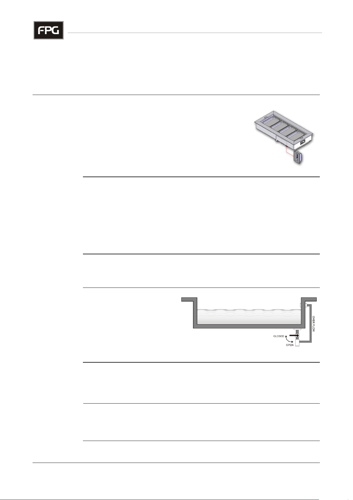
The drop-in well consists of a main assembly, in which
gastronorm dishes of various sizes can be mounted.
A separate control panel is pre-connected to the well
assembly, by a two metre cable.
Operational
Modes
This versatile heated well can be operated in various modes, and with various
dish depths:
Wet well with 65 mm dishes
Wet well with 100 mm dishes
Wet well with 150 mm dishes
Steam well with assorted dish sizes
Dry well with assorted dish sizes
Operating
Temperature
The operating temperature of the well is adjustable, using the digital controller.
There are optimum temperature settings for each of the modes of operation.
Overflow and
Drain
A combined water overflow
and drain is provided.
Ideally this should be
connected to an external
drain. Otherwise a suitable
receptacle must be used.
Larger models are fitted with two drains.
Auto-fill
Auto-fill options are available for all cabinet sizes, see Mechanical Drawings.
A valve, connected to the water level sense unit, a flow control valve and a
sediment trap are plumbed to the mains water supply.
Optional
Lighting
An optional lighting gantry is available. The well assembly has provision for
mounting the gantry and is pre-wired for the heat lamps and water level
indicator.
Configuration
DROP-IN HEATED WELL ASSEMBLIES
-
OPERATION
OPERATION
Part No.21966 Rev. M February 2016 - 8 - Heated Well GN Series
Page 9
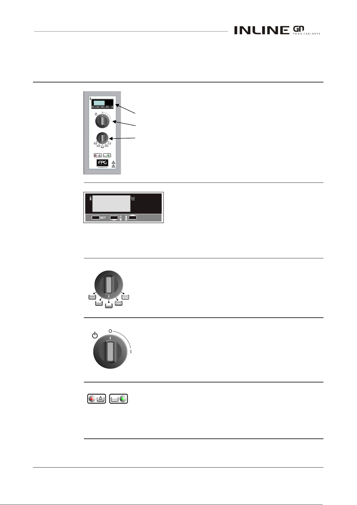
Control Panel
A control panel, mounted on the joinery, provides for all
operational adjustments.
Temperature
Main On/Off Switch
Operating Mode
Indicator lights are also provided to show when the water level is
low and when the heating elements are on.
Temperature
The display normally shows the actual well
temperature.
To adjust the operating temperature, first press and
hold the left hand button for two seconds. Whilst
still pressing it, use the up or down arrow button to change the temperature
setting. Release both buttons to store the new temperature setting.
The display will now revert to showing the actual well temperature.
Operating
Mode
Rotate the mode switch to the appropriate position for the
required dish depth and type of operation.
65mm – 100mm – 150mm – Steam – Dry
On/Off Switch
Rotate this switch to turn the heating on and off.
If an overhead lighting/heating gantry is fitted, it is controlled
by a switch on the support post.
Indicator
Lamps
The water level is monitored, according to the setting of the
mode switch, the lamp coming on if the level is too low.
Detector probes, positioned in the side of the well, ensure the
correct water level for three dish sizes and steam mode.
A second indicator lamp shows when the heating elements are operating.
Controls
DROP-IN HEATED WELL ASSEMBLIES
-
OPERATION
IN-GNH03/4/5/6/8 - 9 - © Future Products Group
Page 10
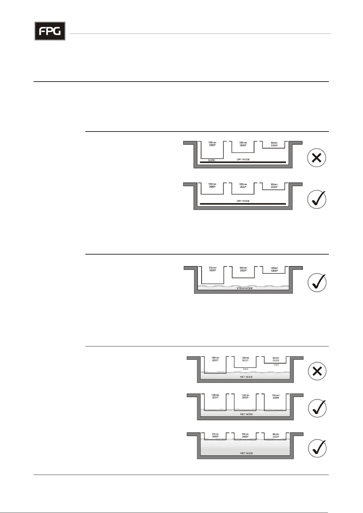
Choice of Mode
It is important to select an appropriate operating mode, to suit the type of food,
the type of dish and the required food temperature.
The actual food temperature can be influenced by many variables, and it is
important to regularly check actual food temperatures with a thermometer.
Dry Mode
In this mode, no water is
used. The air in the well is
heated by the elements, and
the dishes are warmed by
conduction and radiation
through the air.
The capacity of air to conduct
heat to the dishes is low, and
uniform heating is difficult to
achieve. The radiant heat from the elements can cause hot spots, particularly if
deep dishes are used.
This mode works best if the food in the dishes has a high liquid content, to allow
heat circulation inside the dish.
Steam Mode
In this mode, the heating
elements are covered with
water, but the dishes do not
touch the water.
Heat is transferred to the
dishes by the steam. The higher thermal capacity of the water vapour/steam
ensures faster heat transfer and more even dish temperatures than with a dry
well.
Dishes of differing depth can be used, but 150 mm dishes will tend to wet mode.
Wet Mode
In this mode the water level is
higher, so that the dishes are
in contact with the water.
This gives the highest heat
transfer rate to the dishes, and
a uniform temperature is more
easily achieved.
For correct operation, the
dishes should be of equal
depth. Settings are provided
for three sizes, 65 mm, 100
mm and 150 mm deep.
Operating Mode
DROP-IN HEATED WELL ASSEMBLIES
-
OPERATION
Part No.21966 Rev. M February 2016 - 10 - Heated Well GN Series
Page 11
Setting Guide
The following temperature settings for the operating modes are a guide only.
Actual food temperatures should be regularly monitored, to ensure appropriate
storage conditions.
The required settings will depend on ambient conditions, whether overhead heat
lamps are used and whether the dishes have lids etc.
Dry Mode
Temperature
The suggested temperature setting for dry mode operation is 110°C.
Steam Mode
Temperature
The suggested temperature setting for steam mode operation is 95°C.
Wet Mode
Temperature
The suggested temperature setting for wet mode operation is 75°C.
Food
Temperature
In general, hot food should be kept at 65°C or above.
The heated-well MUST have reached its working temperature, before food is
loaded.
Food MUST be pre-heated to the required temperature, before it is placed in the
display dishes. Alternatively a whole filled display dish can be pre-heated, and
exchanged for a dish in the heated-well.
Display Time
The permissible display time will depend on the ambient conditions and food
type. Use of an overhead heat/lighting gantry will increase display times.
Items such as fries, wedges and burgers could typically be displayed for 20
minutes.
Times can be greatly increased if lids are used.
Unsuitable
Food Type
Larger joints of meat are best kept in a closed heated cabinet, to prevent drying
out.
Temperature Settings
DROP-IN HEATED WELL ASSEMBLIES
-
OPERATION
Storage and Display Basics
DROP-IN HEATED WELL ASSEMBLIES
-
OPERATION
IN-GNH03/4/5/6/8 - 11 - © Future Products Group
Page 12
Power Supply
Ensure that power is connected to the cabinet.
Decide on the
Required Mode
If wet or steam operation is to be used, first add water to cover the elements.
The correct water level for the various modes is shown on the depth gauge, on
the inside of the well.
Turn the mode selector to the appropriate setting, to start heating up the well.
The level indicator lamp should be off and the element indicator on.
Caution
Turn on Lights
If fitted
It is important to turn on the overhead heat lamps, whenever steam is escaping
from the heated well, whilst pre-heating and during normal operation.
If this is not done, condensation will cause premature lamp failure.
Pre-heat the
Well
Set the temperature controller to the required setting and allow the well to reach
the required operating temperature, with dishes in place, before adding food.
The well temperature is indicated on the controller display, and the Element On
indicator lamp will extinguish when the set temperature is reached.
To reduce the pre-heating time, the well can be filled with hot water.
NOTE Setting the controller to a higher temperature than required will not
speed up the heating process. Set it to the desired temperature.
Fumes and
Odours
Before first use, operate the cabinet for 4 hours to remove any fumes or odours,
which may be present. This will avoid possible tainting of food.
Load Food
Load with pre-heated food products.
When correctly set, the temperature of pre-heated products will be held above
65C.
This is not an oven, so do NOT place cold products in the dishes.
Monitor
Temperatures
It is important to regularly monitor the temperatures of the food in the dishes.
Trim the electronic controller setting, as necessary, to obtain the required
temperature.
Monitor Water
Level
Monitor the water level indicator lamp, and if the lamp comes on, add more
water to restore the correct level for the chosen operating mode.
Preparation
DROP-IN HEATED WELL ASSEMBLIES
-
OPERATION
Part No.21966 Rev. M February 2016 - 12 - Heated Well GN Series
Page 13
FAULT
POSSIBLE CAUSE
REMEDY
Well does not operate/start
The mains isolating switch is
off, a circuit breaker or fuses
are off at the power board
Turn isolating switch On.
Check external circuit breaker
or fuses in the mains supply
External RCD has tripped
Eliminate leakage current
and reset RCD
The On/Off switch is in the Off
position
Turn control knob to On
Internal MCB has tripped
Have wiring checked and
reset MCB
Well does not reach
temperature
Controller setting disturbed
Re-set controller and re-test
after thirty minutes
Controller is faulty
Have controller replaced
An element is blown
Have the element replaced
Overhead lights not working
(If fitted)
The light switch is OFF
Turn light switch ON
Halogen lamp has failed
Replace lamp
Condensation on lamps
Ensure lamps are ON
whenever steam is present
Internal MCB has tripped
Have wiring checked and
reset MCB
Metal parts corroded
Caustic detergent damage
Order replacement parts
Mineral Deposits on elements
Poor water quality
Condition water supply
Excess water flow (auto-fill)
Incorrect flow valve adjustment
Adjust flow valve
Reduced water flow (auto-fill)
Blocked water sediment trap
Empty sediment trap
Service
Personnel Only
The table entries in italics indicate actions to be taken only by qualified Service
Personnel.
TROUBLE SHOOTING
IN-GNH03/4/5/6/8 - 13 - © Future Products Group
Page 14
Power
ALWAYS TURN THE POWER SUPPLY OFF BEFORE CLEANING.
Water
The water in the well will remain hot for a long time after switching off the
cabinet. Be careful when removing the food dishes or draining the water.
Metal Surfaces
Stainless steel or aluminium surfaces should be cleaned with hot soapy water or
a good quality metal cleaning compound.
DO NOT use abrasive pads or cleaners, as surfaces will be damaged.
Glass
All glass should be cleaned using a good quality glass cleaner and a clean
cloth.
DO NOT use abrasive pads or cleaners, because they will damage the surface
of the glass.
Cautions
DROP-IN HEATED WELL ASSEMBLIES
Exterior
DROP-IN HEATED WELL ASSEMBLIES
-
CLEANING
-
CLEANING
CLEANING
Part No.21966 Rev. M February 2016 - 14 - Heated Well GN Series
Page 15
Cabinet Well
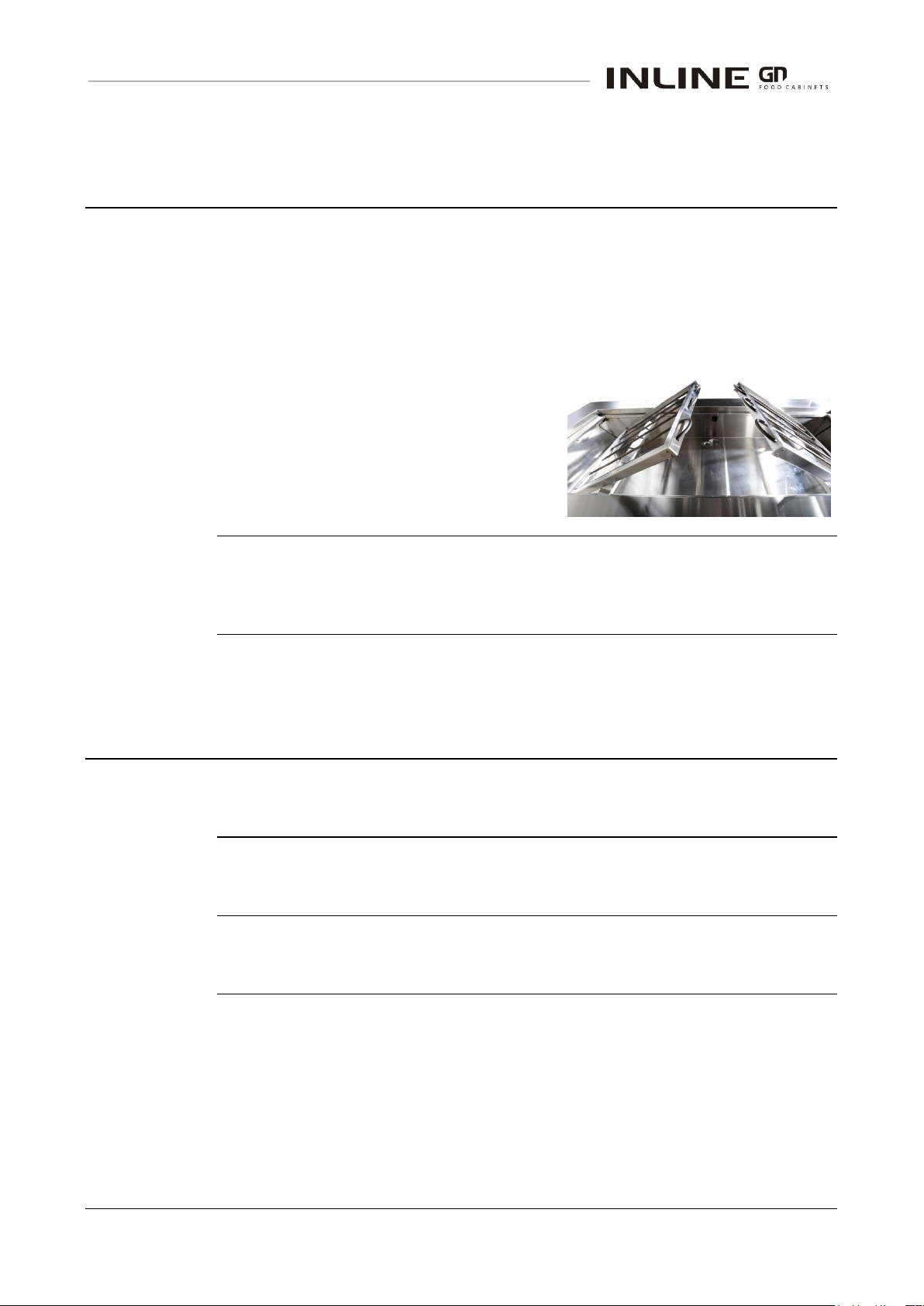
To clean the cabinet well, first lift out the dishes and dividers and then drain the
water out.
A drain tap and overflow, is provided under the well.
Clean the removable strainer from the drain.
CAUTION
The water will remain hot for a long time after switching off the cabinet.
The heating elements can be hinged
upwards to assist with cleaning.
Stainless Steel
Surfaces
The well, supports, grills and stainless steel dishes should be cleaned with hot
soapy water. Do not use abrasive pads or cleaners, as these may damage
surfaces.
Schedules
To maintain optimum performance, cleaning schedules must be regular and
thorough.
Inspection
As part of the cleaning routine, the controls, mechanical parts and electrical
wiring should be inspected for damage, deterioration or need of adjustment.
Correction
If any small faults are found, have them attended to promptly by a competent
serviceman. Don’t wait until they cause a complete breakdown.
Interior
DROP-IN HEATED WELL ASSEMBLIES
-
CLEANING
Routines
DROP-IN HEATED WELL ASSEMBLIES
-
CLEANING
IN-GNH03/4/5/6/8 - 15 - © Future Products Group
Page 16
Compliance
with Local
Requirements
It is very important that your drop-in heated well assembly is installed correctly
and that the operation is correct before use. Installation must comply with local
electrical, health & safety and hygiene requirements.
Unpacking
Unpack and check unit for damage and report any damage to the carrier and
supplier. Report any deficiencies to your supplier.
The well is supplied fully assembled, with the control panel connected to the
main assembly by a two metre cable.
Food dishes and supports may be packed separately.
Site
Preparation
Ensure the well location and any bench cut outs are made to the precise
measurements shown in the Mechanical Drawings. Position the well in its
allocated working position. Use a spirit level to ensure the well is level from side
to side and front to back. (If this is not carried out, uneven temperature
distribution could occur).
Well Assembly
Preparation
Remove all tapes, ties and packers, used to prevent movement during transit.
Lift out the food dishes, grills and divider bars.
Check that all plastic film protection has been removed from surfaces; otherwise
it will melt when the well heats up.
Grounding
WARNING: THIS APPLIANCE MUST BE GROUNDED TO EARTH
The grounding lead, in the mains cable, must always be connected to earth.
A binding post is also provided, to allow the cabinet to be bonded to a surge
grounding conductor or to adjacent equipment, should this be required.
Regulations
DROP-IN HEATED WELL ASSEMBLIES
Setting Up
DROP-IN HEATED WELL ASSEMBLIES
INSTALLATION
-
INSTALLATION
-
INSTALLATION
Continued on next page
Part No.21966 Rev. M February 2016 - 16 - Heated Well GN Series
Page 17
Power Supply
Before connecting to the power supply, check that the local supply is correct to
that shown on the rating plate, located on the side of the well.
To assist with load balancing, the heating elements are star-connected,
enabling the well to be connected to a three phase + neutral supply, or the
phase terminals can be bridged, to use a single phase supply.
Isolation
A mains switch is fitted on the well assembly, next to the control gear panel.
If the well is hard wired to the mains supply, an external means of isolation must
be provided.
If a plug and socket are used, they must be accessible after the well is installed.
Protection
For reasons of safety for personnel, it is strongly recommended to fit a Residual
Current Device, (RCD), in the mains supply to the well.
An over-temperature cut-out is fitted on the well. This will interrupt the mains
supply to the elements, if the well overheats for any reason.
Water Supply
Adjust the flow control valve, to achieve an appropriate fill rate on auto-fill units.
In areas where the water supply has a high mineral content, the water for the
well should be conditioned to prevent deposits forming on the inside of the well
and building up on the heating elements.
In severe cases, thick mineral layers could build up on the elements. This could
result in element failure, if the well is later run in dry mode.
Ventilation
The well is designed to meet the HACCP specifications with free room air
circulation.
The well should not be placed in a location where draughts could cool the
displayed food, i.e. close to a door or air conditioning vent.
Access
Access to the underside of the well is required for draining the water and
servicing.
Fumes and
Odours
Before use, add water to the well and operate the cabinet for 4 hours at 90°C, to
remove any fumes or odours, which may be present. This will avoid possible
tainting of food.
Setting Up cont.
DROP-IN HEATED WELL ASSEMBLIES - INSTALLATION
Location
DROP-IN HEATED WELL ASSEMBLIES
-
INSTALLATION
IN-GNH03/4/5/6/8 - 17 - © Future Products Group
Page 18
Location
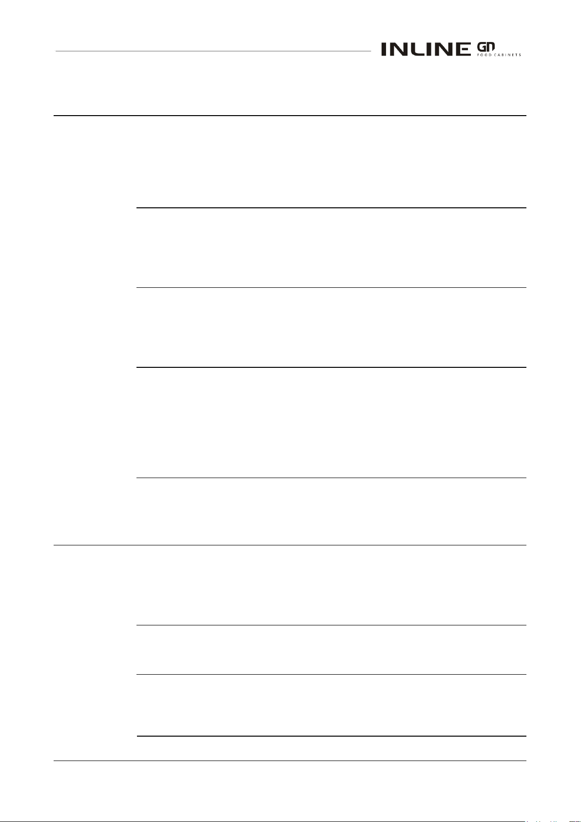
The incoming mains cable is terminated on a
connecting block in an enclosure on the side of the
well. A mains isolating switch is fitted next to the
enclosure.
This enclosure houses the contactor for the heating
elements, the protective MCBs, the over temperature
cut out, and terminals for connecting the elements.
The low power control gear is located behind the control panel. This is
connected to the power enclosure by a two metre cable. It contains the
switches, indicator lamps, the electronic temperature controller, and the
electronic water level indicator, see circuit diagram.
Caution
DO NOT attempt to replace heating elements without isolating the cabinet
at the supply switch or by unplugging it from the mains supply.
Element
Replacement
CAUTION:
This must only
be carried out by
a qualified
service person.
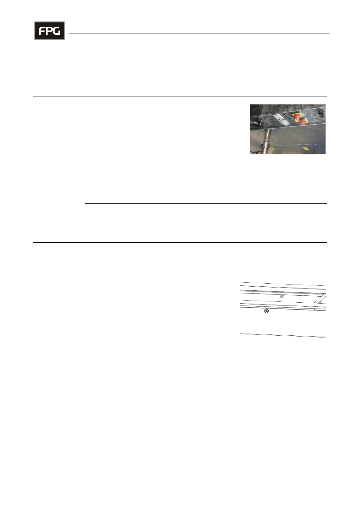
Remove all food dishes and drain the well, to
reveal the heating elements.
Remove the side panels to access the element
terminals.
Each end of the element has two 6.3mm “faston”
spade connectors. One for power and the other
an earth connection.
Pull off the connectors, remove the element retaining nuts and remove the
element.
Fit a new element of the same type, replacing the fixing nuts and spade
connectors.
Take care to fit the earth connectors to the correct terminal at each side of the
element.
Test
Turn the power on and test the heater operation. If normal operation cannot be
restored, by replacing the element, other circuit components will have to be
checked, see Fault Finding.
Control Gear
DROP-IN HEATED WELL ASSEMBLIES
Heating
DROP-IN HEATED WELL ASSEMBLIES
-
SERVICING
-
SERVICING
SERVICING
Part No.21966 Rev. M February 2016 - 18 - Heated Well GN Series
Page 19
Temperature
Probe
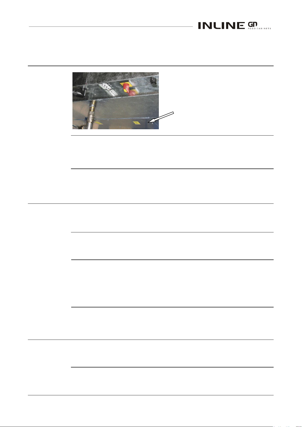
The temperature probe for the controller is
located on the base of the well.
Remove this panel from the underside of
the well to access the probe.
Over
Temperature
Cut Out
The over temperature cut out is mounted on the side of the well, within the
power connection enclosure.
Indicator
Module
The electronic water sensing module is located behind the control panel.
It is connected to the sensing probes and the “water Low” indicator lamp.
Water Sensing
Probes
The water sensing probes are located at various heights in the side of the well.
An earth reference connection is also made to the well wall.
Auto-fill
Some models have auto-fill water control valves, see Mechanical Drawings.
The water valve is operated by the water level sensing module.
Adjust the flow control valve, to achieve an appropriate fill rate.
A sediment trap is fitted on the inlet side of the valve, to avoid malfunction.
Lead
Replacement
If damaged, the mains lead must ONLY be replaced by a qualified service
person.
Heating cont.
DROP-IN HEATED WELL ASSEMBLIES - SERVICING
Water Level Control
DROP-IN HEATED WELL ASSEMBLIES
Mains Lead
DROP-IN HEATED WELL ASSEMBLIES
-
SERVICING
-
SERVICING
IN-GNH03/4/5/6/8 - 19 - © Future Products Group
Page 20
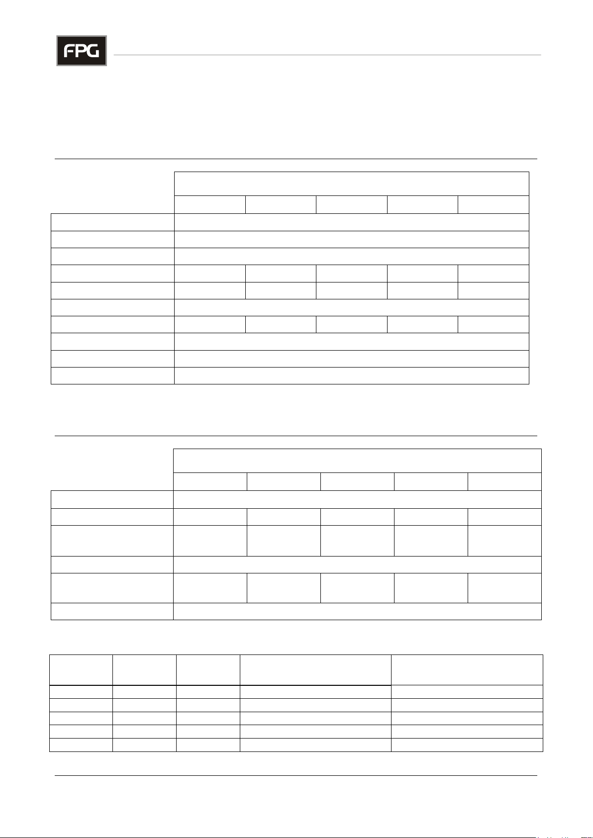
CABINET MODEL
IN-GNH03
IN-GNH04
IN-GNH05
IN-GNH06
IN-GNH08
Height above joinery
18 mm
Depth below joinery
260 mm plus drain tap assembly
Width
805 mm
Length
1320 mm
1660 mm
2000 mm
2340 mm
3020 mm
Dry Weight
123 kg
150 kg
178 kg
206 kg
269 kg
Well Material
Stainless steel
Approx. Display Area
0.45 m
2
0.6 m2
0.75 m2
0.9 m2
1.2 m2
Glass Type
Toughened glass is used in the optional overhead gantry
Top Heat Lamps
Optional overhead heating/lighting gantry available
Climatic Class & IP
All wells are suitable for class N climates and have an IP 22 rating
CABINET MODEL
IN-GNH03
IN-GNH04
IN-GNH05
IN-GNH06
IN-GNH08
Voltage
230 - 240 V 50 Hz 1 or 3 (Star connected)
Power
2.5kW
3.3kW
4.1kW
4.9kW
6.5kW
Current (1 operation)
(excluding gantry)
10.5A
13.8A
17A
20A
28A
Connection
Terminals
Heating Elements
1.6kW
+800W
2 x 1.6kW
2x1.6kW
+800W
3 x 1.6kW
4 x 1.6kW
Heat Lamps
300 W linear halogen lamps in optional overhead gantry
Cabinet
Model
1Ph Current
Draw, No
Light Gantry
1Ph Current
Draw, With
Light Gantry
3Ph+N Current Draw,
No Light Gantry
3Ph+N Current Draw,
With Light Gantry
IN-GNH03
10.5A
14.5A
L1=0.0A, L2=3.5A, L3=7.0A
L1=4.0A, L2=3.5A, L3=7.0A
IN-GNH04
14.0A
19.0A
L1=0.0A, L2=7.0A, L3=7.0A
L1=5.0A, L2=7.0A, L3=7.0A
IN-GNH05
17.5A
24.0A
L1=3.5A, L2=7.0A, L3=7.0A
L1=10.0A, L2=7.0A, L3=7.0A
IN-GNH06
21.0A
29.0A
L1=7.0A, L2=7.0A, L3=7.0A
L1=15.0A, L2=7.0A, L3=7.0A
IN-GNH08
28.0A
38.5A
L1=0.0A, L2=14.0A, L3=14.0A
L1=10.5A, L2=14.0A, L3=14.0A
Mechanical
DROP-IN HEATED WELL ASSEMBLIES
SPECIFICATIONS
-
SPECIFICATIONS
Electrical
DROP-IN HEATED WELL ASSEMBLIES
Details of individual Phase loads
-
SPECIFICATIONS
Part No.21966 Rev. M February 2016 - 20 - Heated Well GN Series
Page 21
Safety Aspects
This drop-in well has been designed to comply with the relevant requirements of
the following specifications:
AS/NZS 3100 : General Requirements for Electrical Equipment
IEC 335: Heated Food Cabinets
AS/NZS 3820 : Essential Safety Requirements
AS/NZS 4417 : Marking of Electrical Products
Ongoing
Development
FPG reserves the right to change specifications and construction, as part of
ongoing product improvement.
Compliance
DROP-IN HEATED WELL ASSEMBLIES
Improvements
DROP-IN HEATED WELL ASSEMBLIES
-
SPECIFICATIONS
-
SPECIFICATIONS
IN-GNH03/4/5/6/8 - 21 - © Future Products Group
Page 22
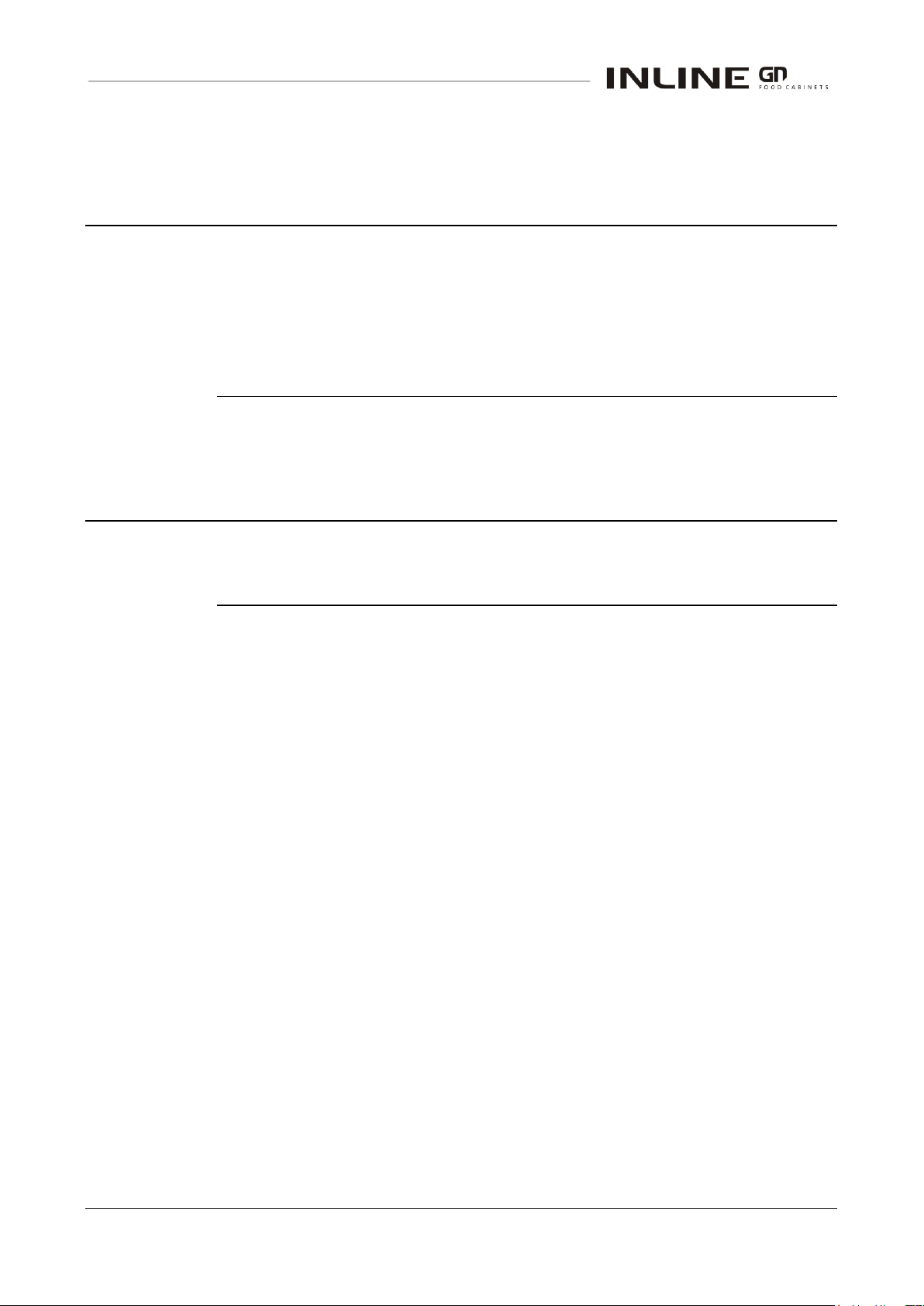
Model: IN-GNH03
Drop-in Heated Well, 3 Pan Bain Marie
Model: IN-GNH03 Auto-fill
Drop-in Heated Well, 3 Pan Bain Marie
ELECTRICAL CIRCUIT DIAGRAMS
Part No.21966 Rev. M February 2016 - 22 - Heated Well GN Series
Page 23
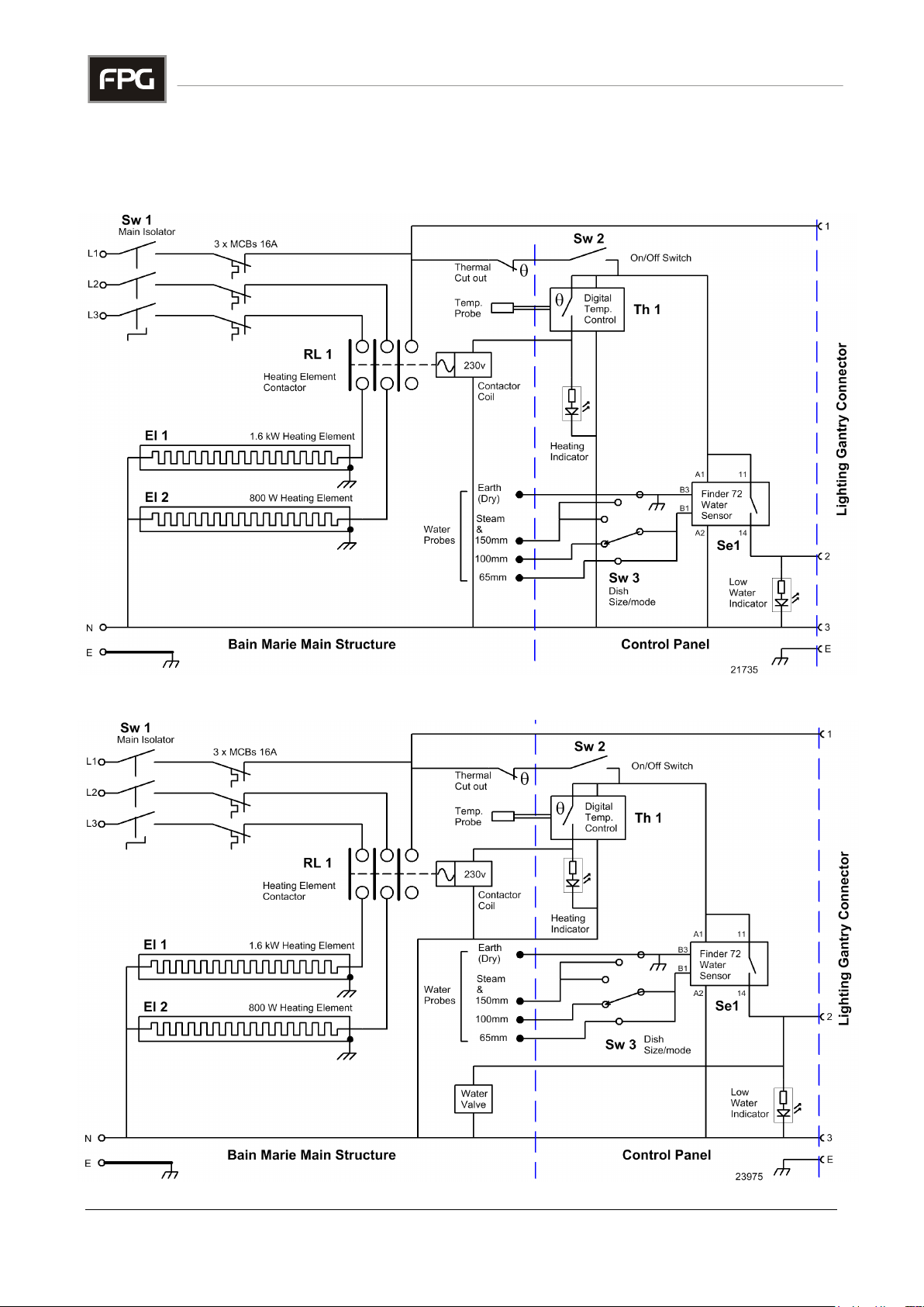
Model: IN-GNH04
Drop-in Heated Well, 4 Pan Bain Marie
Model: IN-GNH04 Auto-fill
Drop-in Heated Well, 4 Pan Bain Marie
ELECTRICAL CIRCUIT DIAGRAMS, Continued
IN-GNH03/4/5/6/8 - 23 - © Future Products Group
Page 24
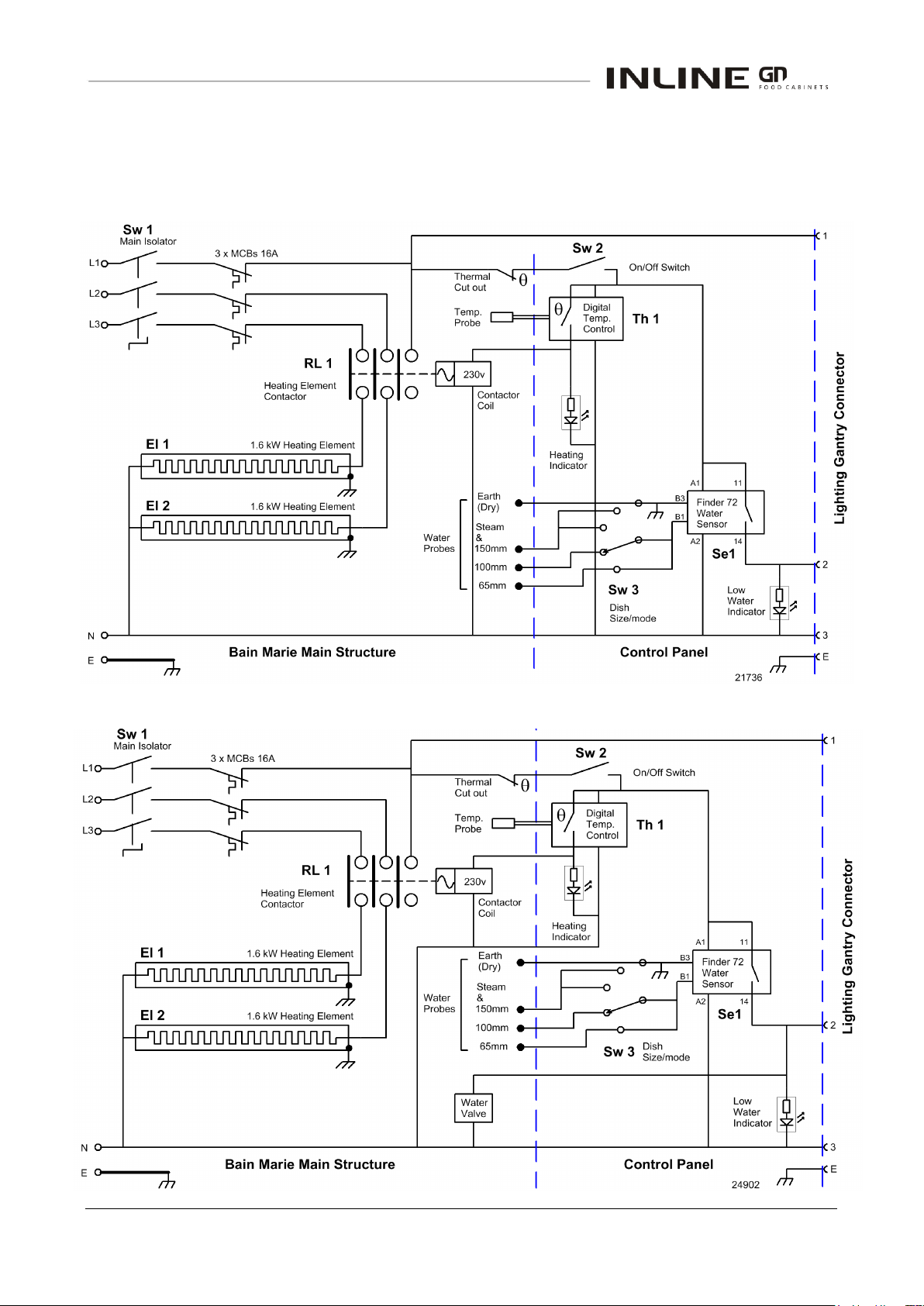
Model: IN-GNH05
Drop-in Heated Well, 5 Pan Bain Marie
Model: IN-GNH05 Auto-fill
Drop-in Heated Well, 5 Pan Bain Marie
ELECTRICAL CIRCUIT DIAGRAMS, Continued
Part No.21966 Rev. M February 2016 - 24 - Heated Well GN Series
Page 25
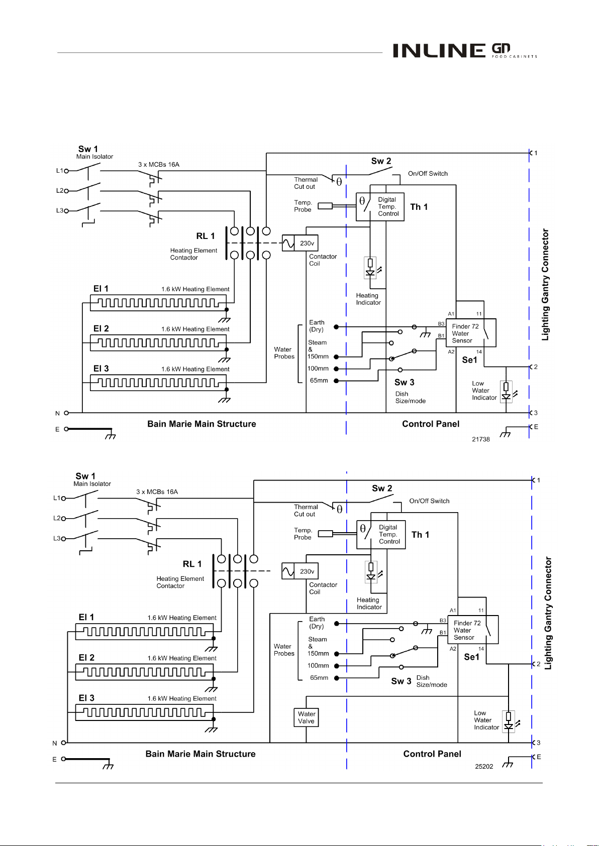
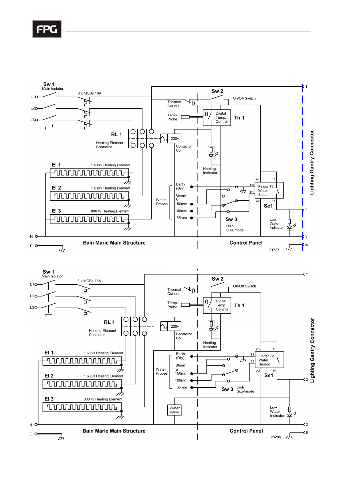
Model: IN-GNH06
Drop-in Heated Well, 6 Pan Bain Marie
Model: IN-GNH06 Auto-fill
Drop-in Heated Well, 6 Pan Bain Marie
ELECTRICAL CIRCUIT DIAGRAMS, Continued
IN-GNH03/4/5/6/8 - 25 - © Future Products Group
Page 26
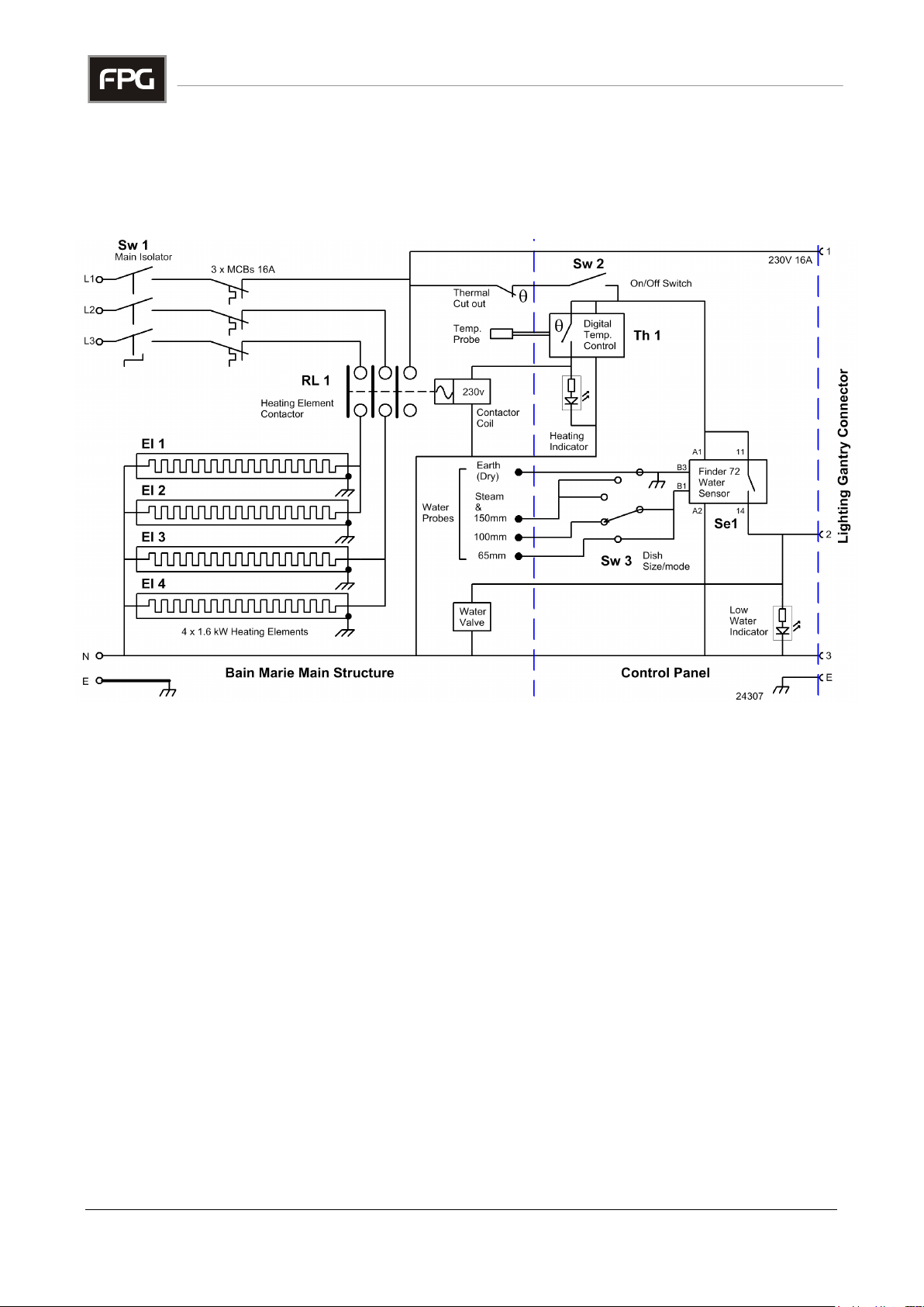
Model: IN-GNH08 Auto-fill
Drop-in Heated Well, 8 Pan Bain Marie
ELECTRICAL CIRCUIT DIAGRAMS, Continued
Part No.21966 Rev. M February 2016 - 26 - Heated Well GN Series
Page 27
Assembly
Serial Number
When ordering spare parts, it is important to quote the Serial Number printed on
the label fixed to the control panel.
This serial number will enable FPG to trace details of the build specification of
your particular assembly, and hence ensure that spare parts are fully
compatible.
To satisfy warranty conditions, and ensure optimum performance, use
only FPG supplied spare parts.
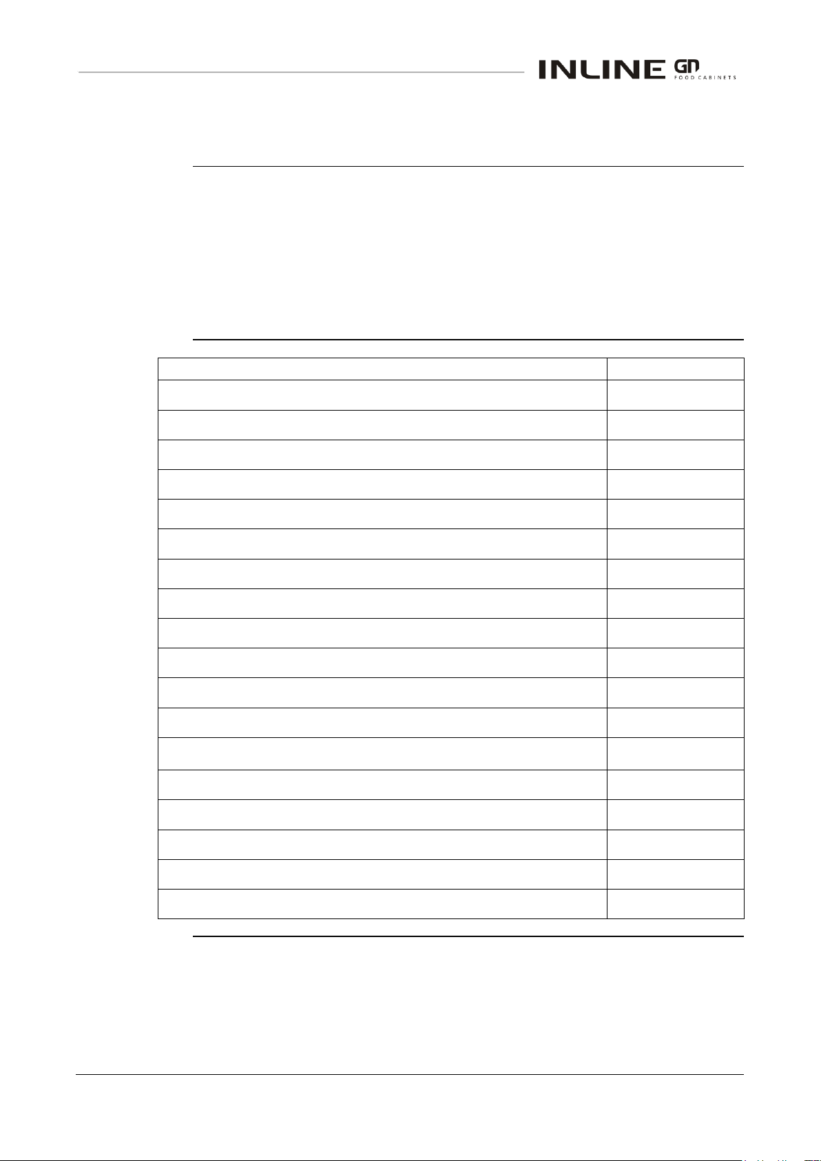
Part Description
FPG Part No.
Mains isolation switch 3-pole
11870
On/Off Switch
14372
Knob for On/Off switch
14374
Mode Switch (AC125V 0.3A)
24961
Knob for Mode switch
14374
Digital Thermostat
65529
Thermostat Probe
21620
Water Sensor, Finder 72
25309
Water valve 230V
20827
Level Sensor Probe
21601
Thermal cut-out
22040
Circuit Breaker 16A
19869
Element Contactor 3
16825
Heating Element 800 W
21525
Heating Element 1.6 kW
21524
Product Manual for Drop-in Heated Well Assemblies
21966
SPARE PARTS
IN-GNH03/4/5/6/8 - 27 - © Future Products Group
Page 28
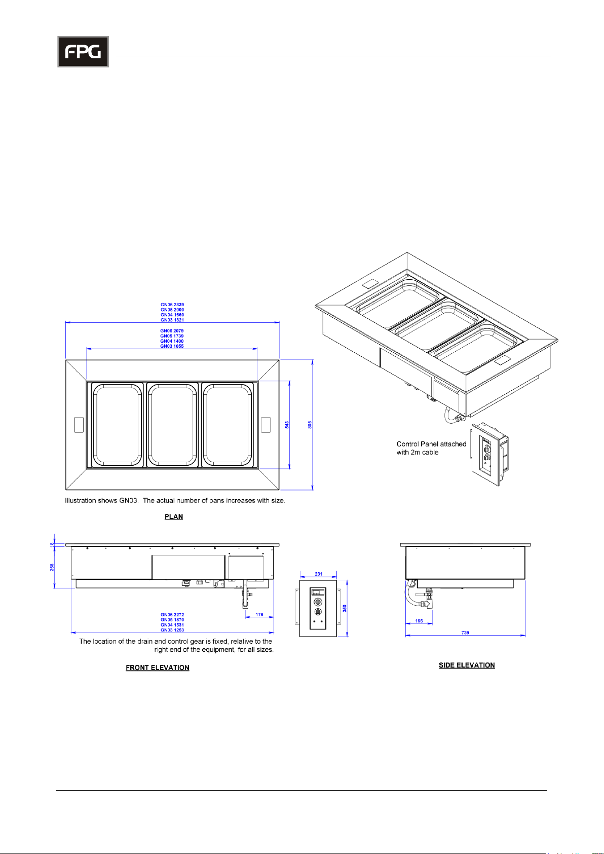
MECHANICAL DRAWINGS
Dimensions
DROP-IN HEATED WELL ASSEMBLIES
IN-GNH03 to GNH06
-
MECHANICAL DRAWINGS
Part No.21966 Rev. M February 2016 - 28 - Heated Well GN Series
Page 29
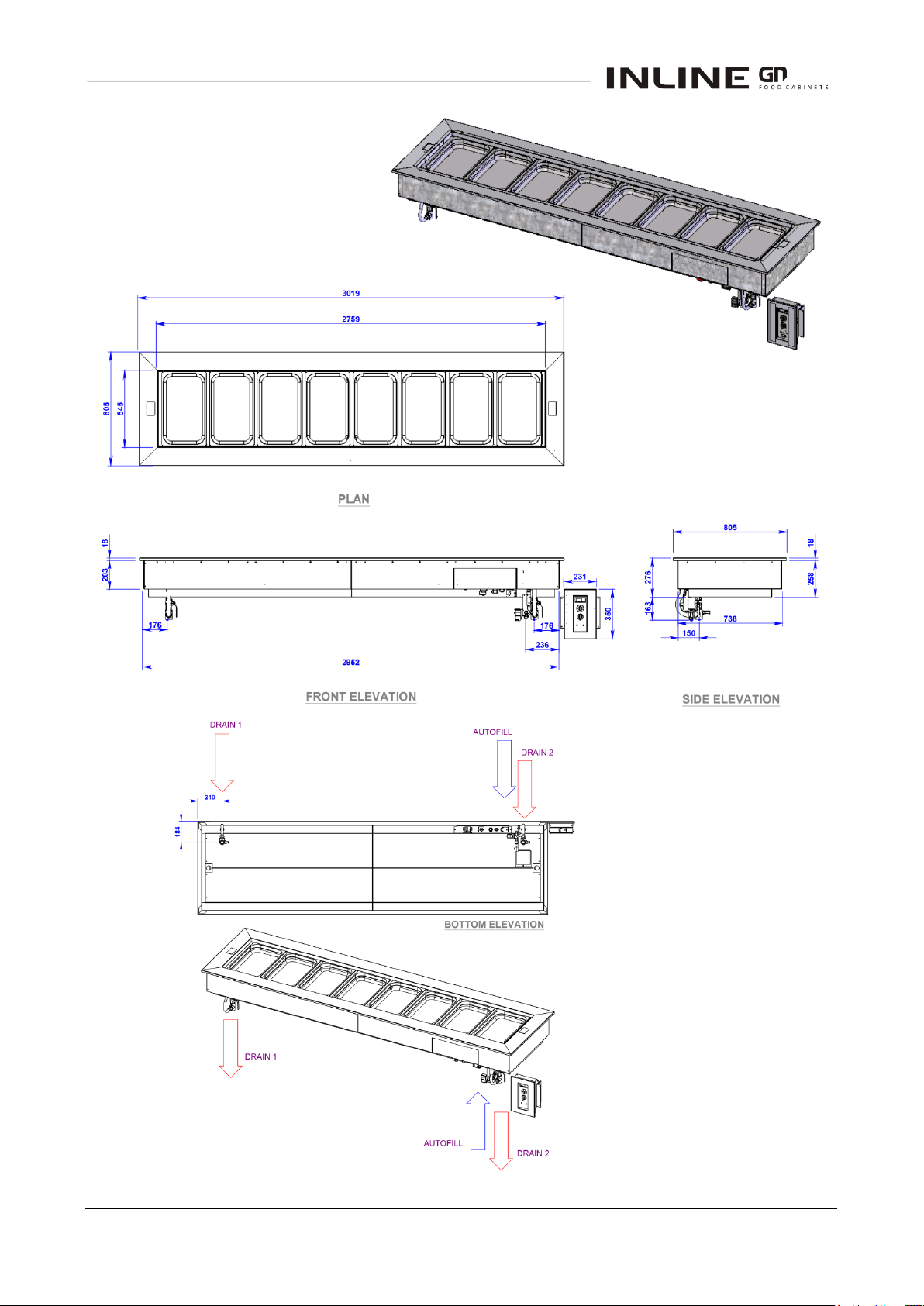
IN-GNH08
IN-GNH03/4/5/6/8 - 29 - © Future Products Group
Page 30
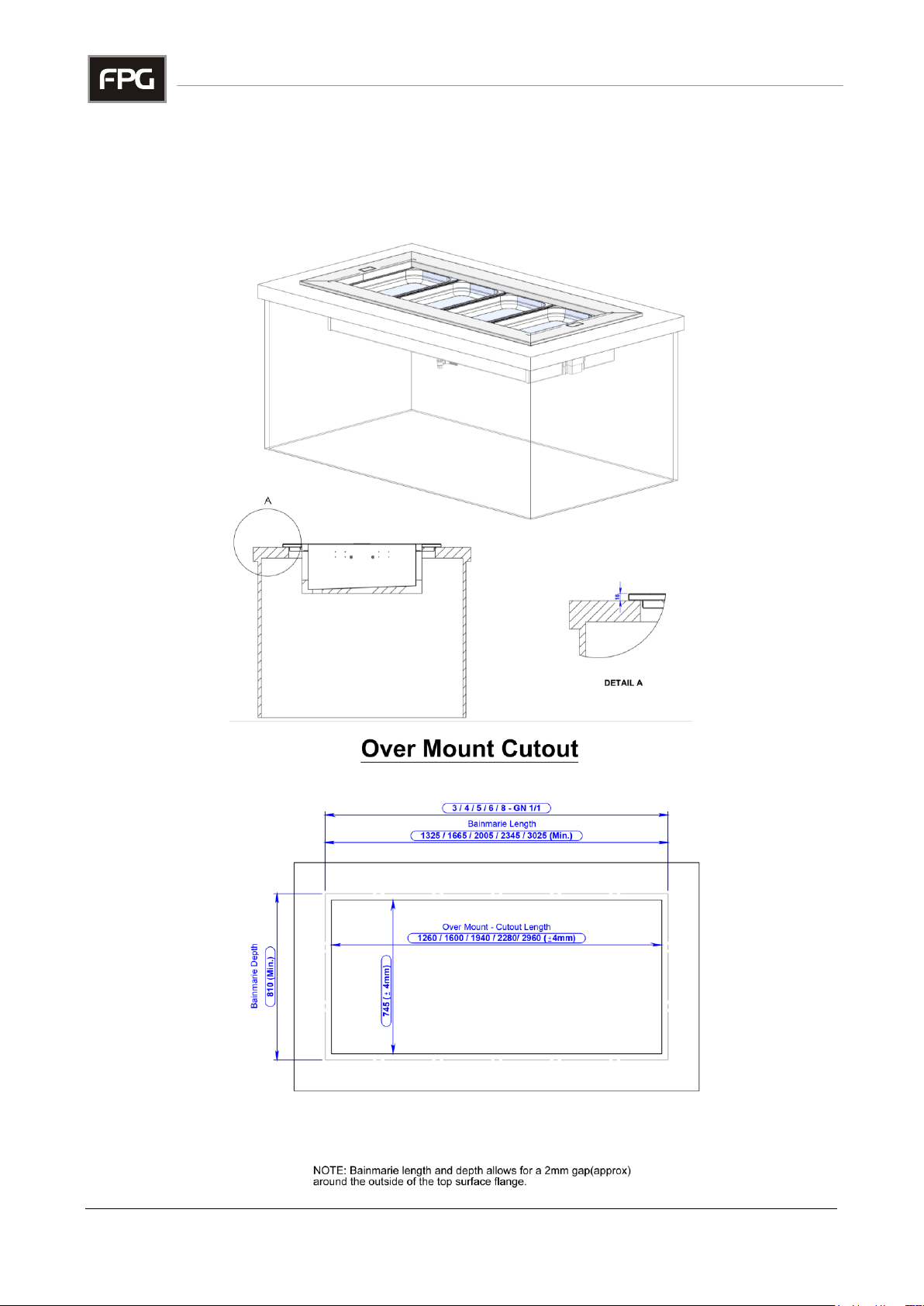
Bench Cut-outs
DROP-IN HEATED WELL ASSEMBLIES
Over Mount Installation
-
MECHANICAL DRAWINGS
Part No.21966 Rev. M February 2016 - 30 - Heated Well GN Series
Page 31
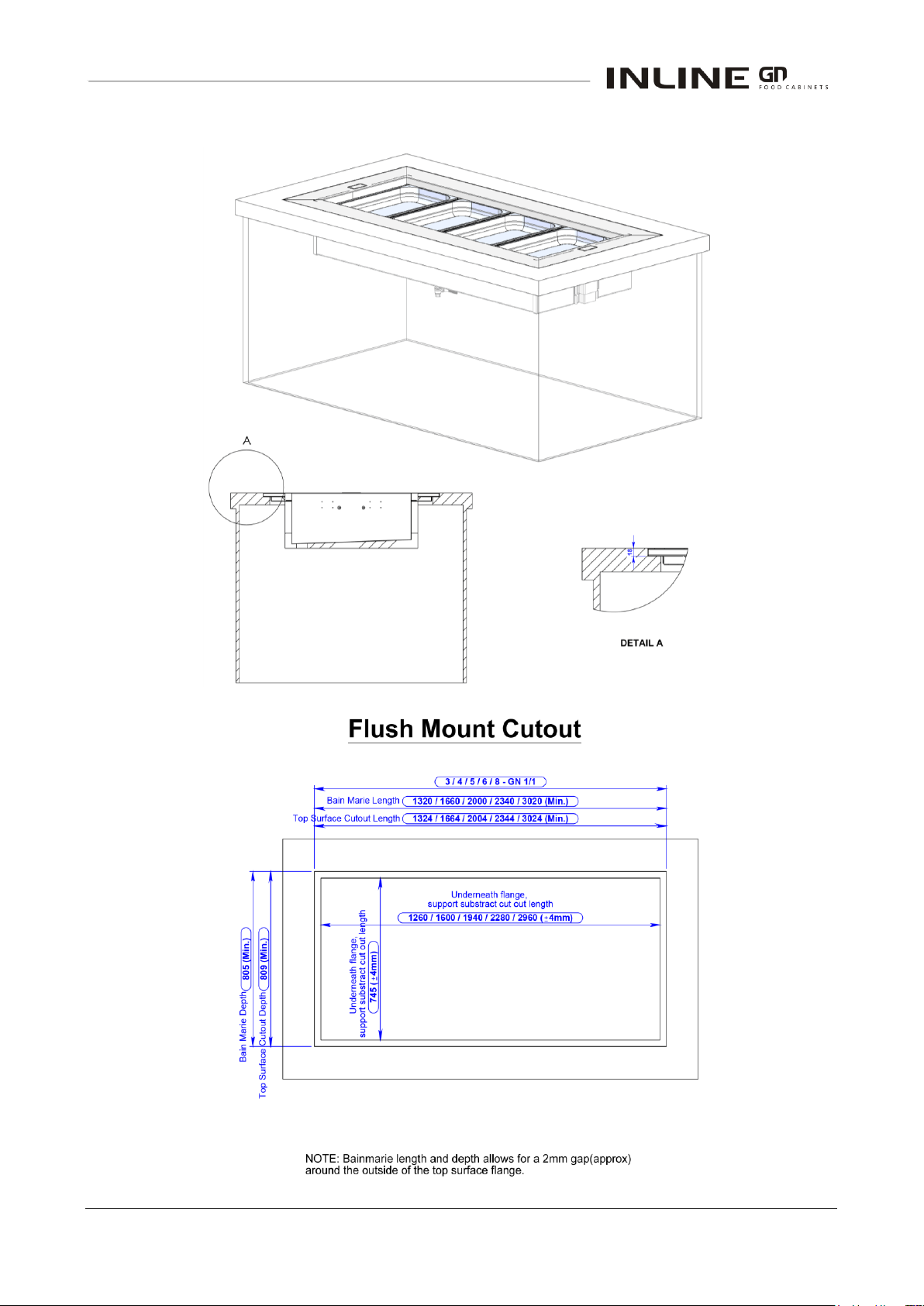
Flush Mount Installation
IN-GNH03/4/5/6/8 - 31 - © Future Products Group
Page 32
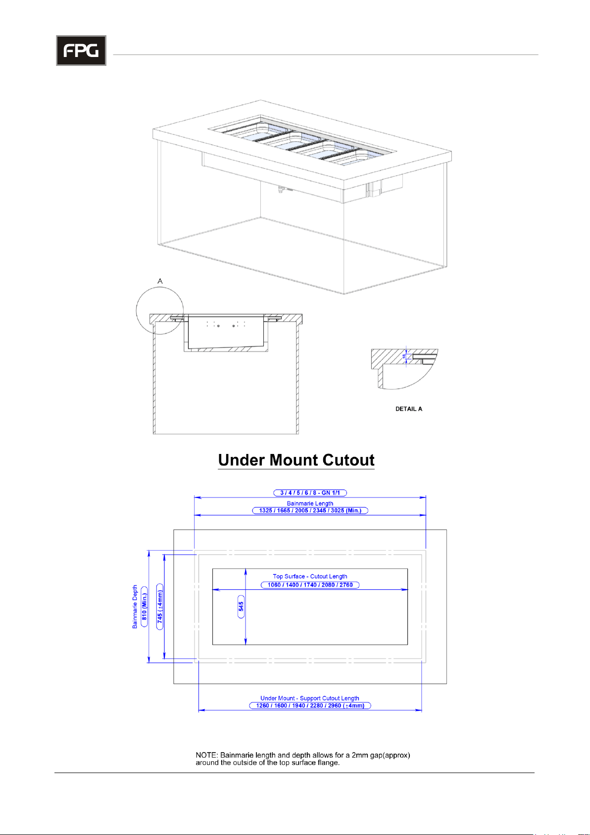
Under Mount Installation
Part No.21966 Rev. M February 2016 - 32 - Heated Well GN Series
Page 33
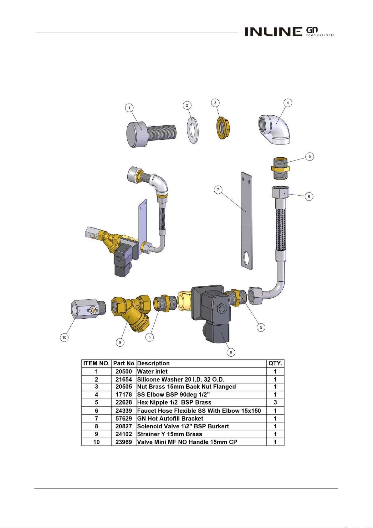
Auto-fill Components
DROP-IN HEATED WELL ASSEMBLIES
-
MECHANICAL DRAWINGS
IN-GNH03/4/5/6/8 - 33 - © Future Products Group
Page 34

Part No.21966 Rev. M February 2016 - 34 - Heated Well GN Series
Page 35

IN-GNH03/4/5/6/8 - 35 - © Future Products Group
Page 36
Part No.21966 Rev. M February 2016
 Loading...