

Page 1
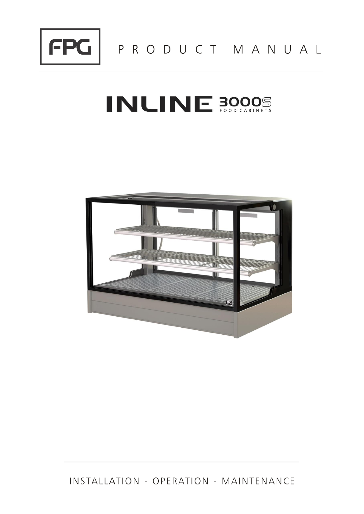
Heated Cabinets
Square Format
Page 2

Part No.26113 Rev. G September 2018 - 2 - Inline 3000 Square Series Cabinets
Copyright © September 2018 Future Products Group Limited.
All rights reserved.
No part of this publication may be reproduced, stored in a retrieval
system, or transmitted in any form or by any means, electronic,
mechanical, photocopying, recording or otherwise, without the prior
written permission of Future Products Group Ltd.
Page 3

IN 3H06/09/12/15 - 3 - © Future Products Group
Table of Contents
INTRODUCTION ................................................................................................................ 6
Welcome .......................................................................................................................................................... 6
Future Products Group (FPG) ................................................................................................................... 6
Guidance and Help .................................................................................................................................... 6
Warranty .......................................................................................................................................................... 6
Warranty Period ........................................................................................................................................ 6
Liability Exceptions .................................................................................................................................... 7
Specific Exclusions .................................................................................................................................... 7
Assessment ............................................................................................................................................... 7
Time Limit .................................................................................................................................................. 7
Caution ...................................................................................................................................................... 7
OPERATION ...................................................................................................................... 8
Cabinet Layout................................................................................................................................................ 8
3000 Square Series Cabinets.................................................................................................................... 8
Door Configuration .................................................................................................................................... 8
Shelf Lighting............................................................................................................................................. 8
Controls ........................................................................................................................................................... 8
Control Panel............................................................................................................................................. 8
Main Switch ................................ ................................ ................................ ............................................... 8
Heating ...................................................................................................................................................... 8
Thermometer ............................................................................................................................................. 8
Preparation ..................................................................................................................................................... 9
Shelf Location and Ticketing ..................................................................................................................... 9
Shelf Adjustment ....................................................................................................................................... 9
Power Supply ............................................................................................................................................ 9
Set the Temperature ................................................................................................................................. 9
Fumes and Odours .................................................................................................................................... 9
Load Cabinet ........................................................................................................................................... 10
WARNING: Aluminium Foil...................................................................................................................... 10
Close all Doors ........................................................................................................................................ 10
Turn on Lights ......................................................................................................................................... 10
Door Opening .......................................................................................................................................... 10
TROUBLE SHOOTING ................................ ................................ .................................... 11
CLEANING ...................................................................................................................... 12
Cautions ........................................................................................................................................................ 12
Power ...................................................................................................................................................... 12
Water ....................................................................................................................................................... 12
Exterior .......................................................................................................................................................... 12
Metal Surfaces ........................................................................................................................................ 12
Glass ....................................................................................................................................................... 12
Sliding Doors ........................................................................................................................................... 12
Page 4

Part No.26113 Rev. G September 2018 - 4 - Inline 3000 Square Series Cabinets
Interior ........................................................................................................................................................... 13
Cabinet Well ............................................................................................................................................ 13
Trays, Racks, Shelves & Air Grills ........................................................................................................... 13
Routines ........................................................................................................................................................ 13
Schedules................................................................................................................................................ 13
Inspection ................................................................................................................................ ................ 13
Correction ................................................................................................................................................ 13
INSTALLATION ................................................................................................ ............... 14
Regulations ................................................................................................................................................... 14
Compliance with Local Requirements ..................................................................................................... 14
Setting Up ..................................................................................................................................................... 14
Unpacking ............................................................................................................................................... 14
Site Preparation....................................................................................................................................... 14
Cabinet Preparation ................................................................................................................................ 14
Shelf Trays .............................................................................................................................................. 14
Grounding................................................................................................................................................ 15
Power Supply .......................................................................................................................................... 15
Isolation ................................................................................................................................................... 15
Location ........................................................................................................................................................ 15
Ventilation................................................................................................................................................ 15
Access ..................................................................................................................................................... 15
Fumes and Odours .................................................................................................................................. 15
SERVICING ..................................................................................................................... 16
Control Gear ................................................................................................................................................. 16
Location ................................................................................................................................................... 16
Lighting ......................................................................................................................................................... 16
Caution .................................................................................................................................................... 16
Shelf Lights.............................................................................................................................................. 16
Test Lighting Components ...................................................................................................................... 16
Access to LED Strips ............................................................................................................................... 16
LED Strip Replacement ........................................................................................................................... 17
Heating .......................................................................................................................................................... 17
Caution .................................................................................................................................................... 17
Element Replacement ............................................................................................................................. 17
Test ......................................................................................................................................................... 17
Caution .................................................................................................................................................... 17
Door Seals ..................................................................................................................................................... 18
Seal Replacement ................................................................................................................................... 18
Sliding Doors ........................................................................................................................................... 18
Mains Lead .................................................................................................................................................... 18
Lead Replacement .................................................................................................................................. 18
Page 5

IN 3H06/09/12/15 - 5 - © Future Products Group
SPECIFICATIONS ........................................................................................................... 19
Mechanical .................................................................................................................................................... 19
Electrical ....................................................................................................................................................... 19
Compliance ................................................................................................................................................... 20
Standards ................................................................................................................................ ................ 20
Performance Aspects .............................................................................................................................. 20
Operational Safety ................................................................................................................................... 20
Improvements ................................................................................................ ................................ ............... 20
Ongoing Development ............................................................................................................................. 20
ELECTRICAL CIRCUIT DIAGRAMS ............................................................................... 21
Model: IN 3H06-SQ ................................................................................................................................. 21
Model: IN 3H09-SQ ................................................................................................................................. 21
Model: IN 3H12-SQ ................................................................................................................................. 22
Model: IN 3H15-SQ ................................................................................................................................. 22
SPARE PARTS ................................................................................................................ 23
Cabinet Serial Number ............................................................................................................................ 23
MECHANICAL DRAWINGS ............................................................................................. 25
Dimensions ................................................................................................................................................... 25
Cabinet Variants ...................................................................................................................................... 25
IN 3H06/09/12/15-SQ Counter Top Mounting ........................................................................................ 25
IN 3H06/09/12/15-SQ In Counter Mounting ........................................................................................... 26
IN 3H06/09/12/15-SQ Free Standing ..................................................................................................... 27
Page 6
Part No.26113 Rev. G September 2018 - 6 - Inline 3000 Square Series Cabinets
INTRODUCTION
Welcome
HEATED CABINETS
-
INTRODUCTION
Future
Products
Group (FPG)
Welcome to the world of FPG! Our products are designed and engineered to
give you the optimal performance that you deserve with innovative visual
merchandising appeal.
We are confident that you will be delighted with your state of the art inline food
service cabinet, and that it will become a valued appliance in your store.
Guidance and
Help
Any new appliance can seem very complex and confusing at first glance. To
ensure you receive the utmost benefit from your new inline cabinet, there are
two things you can do.
• Before operating the cabinet, please read the instruction book carefully and
follow its recommendations. The time taken will be well spent. These
instructions both general and technical tell you how to install, operate and
look after your inline food service cabinet so that you can receive the full
benefits that this cabinet has to offer.
• These instructions cannot, however, cover all eventualities. If you are
unsure of any aspect of the installation, instructions or performance of your
cabinet, contact your dealer promptly or contact us via email to
[email protected].
Warranty
HEATED CABINETS
-
INTRODUCTION
Warranty
Period
Future Products Group Limited warrants, to the original purchaser of an FPG
manufactured food service cabinet that for ONE YEAR (12 months), from the
date of purchase, any defect in workmanship or material resulting in the product
malfunctioning while under correct use will be rectified.
Liability under this warranty is limited to replacing or repairing a part, without
charge.
Continued on next page
Page 7
IN 3H06/09/12/15 - 7 - © Future Products Group
Warranty cont.
HEATED CABINETS - INTRODUCTION
Liability
Exceptions
Liability under this warranty does not include:
• Any loss, or damage or expenses directly or indirectly arising from use or
inability to use the product or from any other cause.
• Any part of the cabinet which has been subject to misuse, neglect,
alteration, incorrect installation, accident, or damage caused by
transportation, use of abrasive or caustic chemicals, flooding, fire or acts of
God.
• Any damage or malfunction resulting from the use of non-FPG supplied
spare parts.
Specific
Exclusions
The following are specifically excluded from warranty:
• Breakage of glass or plastic components or the replacement of fluorescent
tubes or gaskets.
• Failure to re-assemble the cabinet correctly after cleaning.
• Fair wear and tear.
Assessment
The liability under this warranty is dependent on an assessment by FPG, to
determine the defect in workmanship or materials.
Time Limit
FPG does not guarantee that any service to be performed under this warranty
will be carried out within any particular time limit.
Caution
No warranty claim will be accepted unless authorised by FPG prior to
commencement of service.
Page 8
Part No.26113 Rev. G September 2018 - 8 - Inline 3000 Square Series Cabinets
OPERATION
Cabinet Layout
HEATED CABINETS
-
OPERATION
3000 Square
Series Cabinets
The 3000 Square Series cabinets include Ambient, Heated and Refrigerated
models.
The cabinets are designed for bench mounting. They may either sit on the
bench, or be recessed to the lower glass edge level.
A free-standing version is also available.
Door
Configuration
Sliding doors can be fitted to the front and back of the cabinets.
Fixed glass can be fitted in place of doors at the front.
Shelf Lighting
Cabinets are fitted with a top light as standard. Lights below each shelf are
available as an optional extra, at the time of ordering.
Cabinets are fitted with high efficiency LED lighting.
Controls
HEATED CABINETS
-
OPERATION
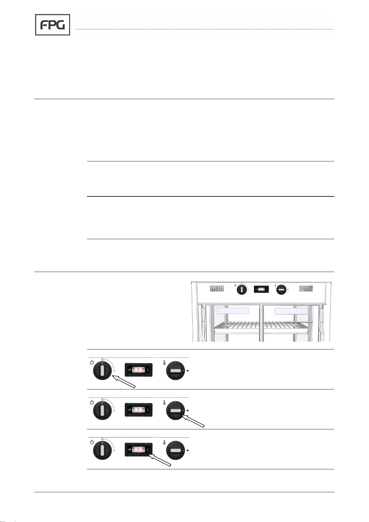
Control Panel
The controls are mounted on
the back of the cabinet, at the
top.
There is a main switch, a
thermometer and a thermostat.
Main Switch
To turn the cabinet on, rotate the switch, with
the on/off symbol.
Heating
Set the desired temperature with the
thermostat control knob. Turn it to the off
mark when heating is not required.
Thermometer
The thermometer indicates the internal
temperature of the cabinet.
Page 9
IN 3H06/09/12/15 - 9 - © Future Products Group
Preparation
HEATED CABINETS
-
OPERATION
Shelf Location
and Ticketing
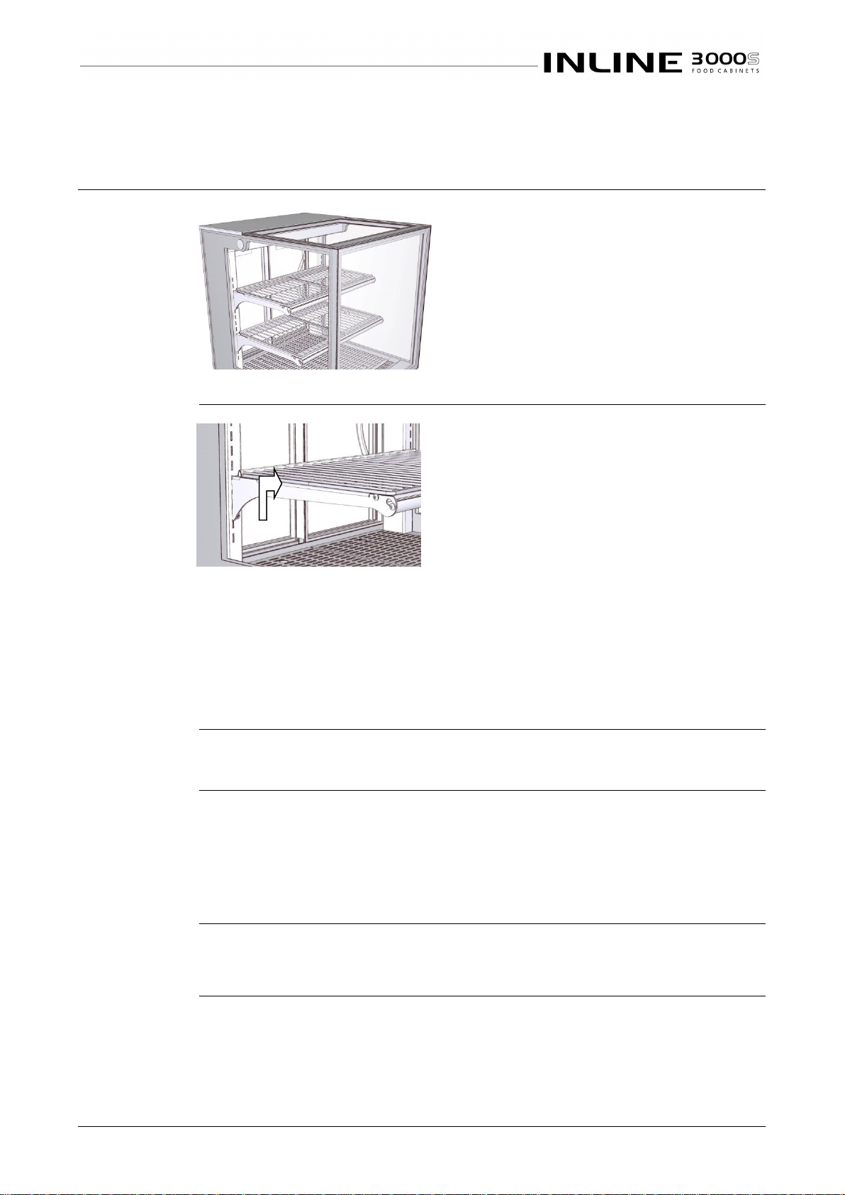
The shelves are adjustable in height and can
easily be moved up or down, to match
product size.
The movement is restricted to 50mm,
because of the electric cables to the lights.
For greater movement contact the
manufacturer or supplier for advice, as
electrical modifications may be required.
Optional ticketing/label strips may be fitted to the front and rear of the shelves.
Shelf
Adjustment
To move the shelf brackets, first remove the
sliding doors and the shelf trays.
Using two people, one on each bracket, lift the
brackets straight up firmly and then pull the
brackets forward, to disengage them from the
slots in the support posts.
Insert the brackets into their new position, and
push bracket down firmly.
The brackets may be positioned to give two different degrees of slope to the
shelves.
Refit all shelf trays and doors.
N.B. Make sure brackets are pushed down as far as they can go. Failure
to do this may result in shelf collapse, when loaded with product.
Power Supply
Ensure that power is connected to the cabinet.
Set the
Temperature
Set the thermostat to the desired temperature, 75 degrees Celsius is the
recommended setting to maintain food temperature within food safety
guidelines.
NOTE Setting the dial to a higher temperature than required will not speed up
the heating process. Set it to the desired temperature.
Fumes and
Odours
Before use, operate the cabinet for 4 hours to remove any fumes or odours,
which may be present. This will avoid possible tainting of food.
Continued on next page
Page 10

Part No.26113 Rev. G September 2018 - 10 - Inline 3000 Square Series Cabinets
Preparation cont.
HEATED CABINETS - OPERATION
Load Cabinet
Load the cabinet with pre-heated product.
The cabinet is designed to maintain the temperature of pre-heated product
above 65C.
It is not an oven, and consequently, if cold product is introduced, there could be
a considerable delay before the operating temperature rises to the normal
operating level.
WARNING:
Aluminium Foil
Do NOT place aluminium foil on the base
trays. This will disrupt the convection
circulation of air, and cause uneven heating.
Blockage of air vents may cause severe
overheating of the cabinet base.
Close all Doors
It is important to keep all cabinet doors closed. If doors are not fully closed, an
even temperature will not be maintained within the cabinet.
Turn on Lights
When ready for service, turn on the cabinet lights.
Door Opening
The cabinet is designed to maintain food at a temperature above 65C. The
heating system is designed to maintain this temperature with the doors being
opened and closed up to sixty times per hour.
If the doors are left open for an extended period the temperature will fall. Once
the doors are closed the temperature will take some time to rise to the normal
operating level. The longer the doors are open the longer the time to restore
normal operating temperature.
Page 11
IN 3H06/09/12/15 - 11 - © Future Products Group
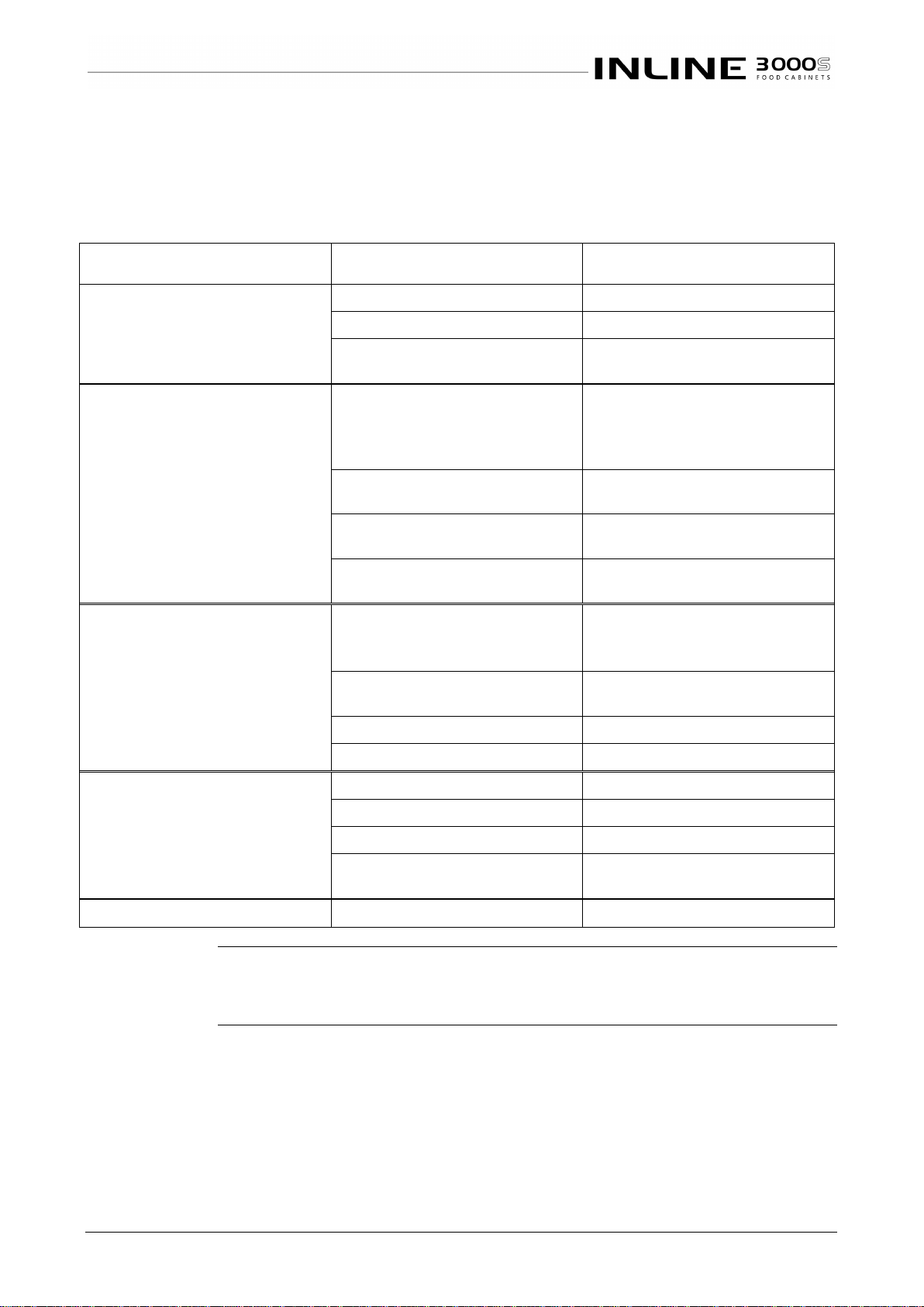
TROUBLE SHOOTING
FAULT
POSSIBLE CAUSE
REMEDY
Doors are not sliding smoothly
Door not in track
Install door correctly in track
Debris in track
Clean door tracks (see cleaning)
Lack of lubricant
Apply food grade lubricant to
door track
Cabinet does not operate/start
The mains isolating switch on
the wall, circuit breaker or
fuses are off at the power
board
Turn isolating switch circuit
breaker or fuses on
The main switch is off
Rotate the switch to the ON
position
The thermostat is in the OFF
position
Turn control knob to desired
temperature
Internal fuse blown
Have wiring checked and
replace fuse (5A Slow Blow)
Cabinet does not reach
temperature
One or more doors is open
Close doors and re-test
temperature after thirty
minutes
Thermostat setting disturbed
Re-set thermostat and re-test
after thirty minutes
Thermostat is faulty
Have thermostat replaced
An element is blown
Have the element replaced
Cabinet lights not working
The main switch is OFF
Turn main switch ON
LED Power supply has failed
Replace LED power supply
LED strip has failed
Replace the LED assembly
Fuse has blown
Check wiring and replace
fuse (5A Slow Blow)
Aluminium parts corroded
Caustic detergent damage
Order replacement parts
Service
Personnel Only
The table entries in italics indicate actions to be taken only by qualified Service
Personnel.
Page 12
Part No.26113 Rev. G September 2018 - 12 - Inline 3000 Square Series Cabinets
CLEANING
Cautions
HEATED CABINETS
-
CLEANING
Power
ALWAYS TURN THE POWER SUPPLY OFF BEFORE CLEANING.
Water
THIS UNIT IS NOT WATERPROOF. DO NOT USE A WATER JET SPRAY TO
CLEAN THE INTERIOR OR EXTERIOR OF THIS CABINET.
Exterior
HEATED CABINETS
-
CLEANING
Metal Surfaces
Stainless steel or aluminium surfaces should be cleaned with hot soapy water or
a good quality metal cleaning compound. DO NOT clean surfaces with abrasive
pads or cleaners, as paint, stainless steel and aluminium surfaces will be
damaged.
Glass
All glass should be cleaned using a good quality glass cleaner and a clean
cloth.
DO NOT use abrasive pads or cleaners, because they will damage the surface
of the glass.
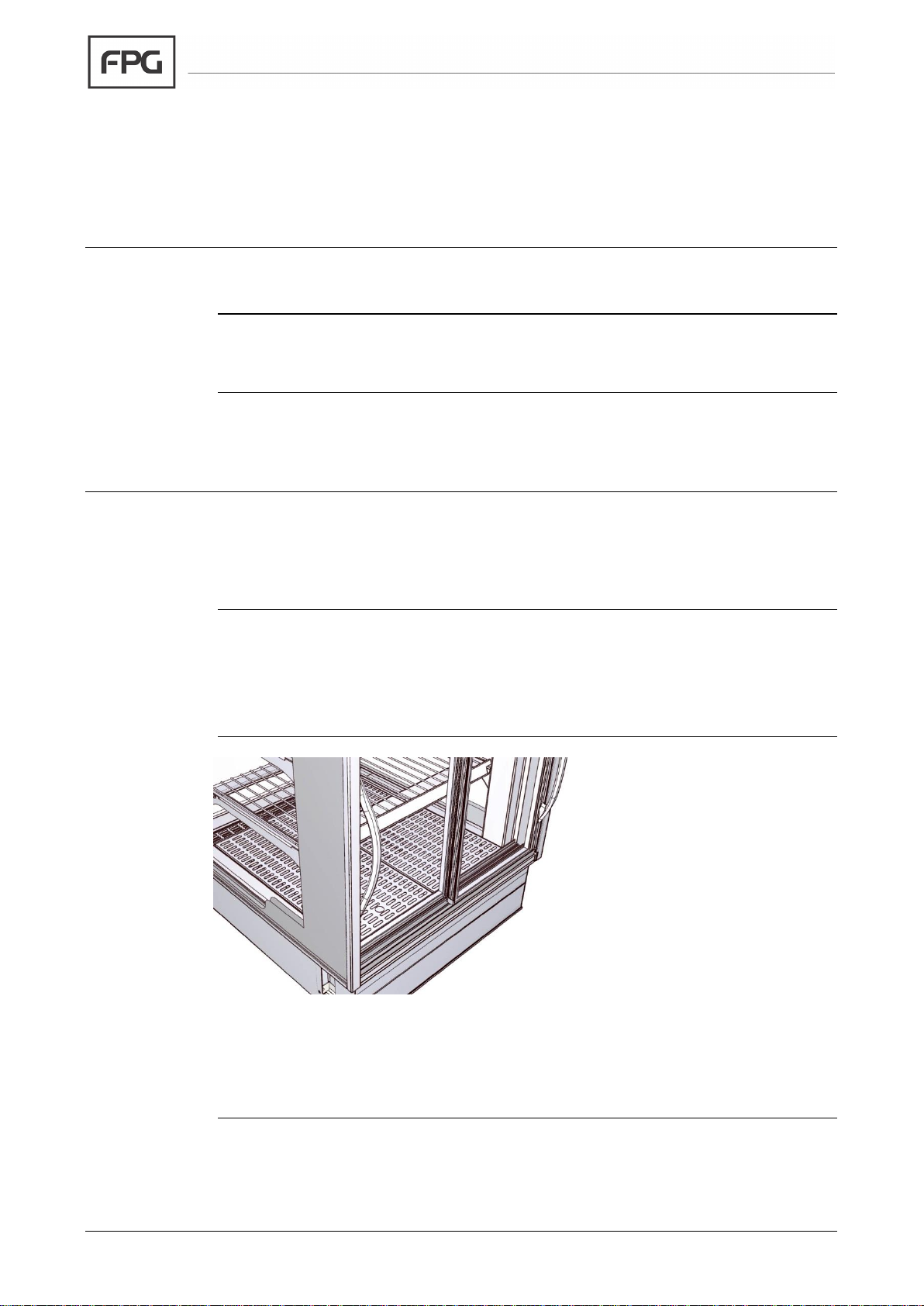
Sliding Doors
Sliding glass doors are located
by plastic guides at the top and
bottom.
The doors can be removed for
cleaning by sliding the door to a
central position, placing hands
either side of the door, lifting it
up and then swinging it out at
the bottom.
When replacing doors, make
sure that they are located in the
correct slots, top and bottom.
The left door should be in the inner slots, and the right door in the outer slots.
Sliding door tracks should be vacuumed out regularly to keep doors sliding
freely.
Continued on next page
Page 13
IN 3H06/09/12/15 - 13 - © Future Products Group
Interior
HEATED CABINETS
-
CLEANING
Cabinet Well
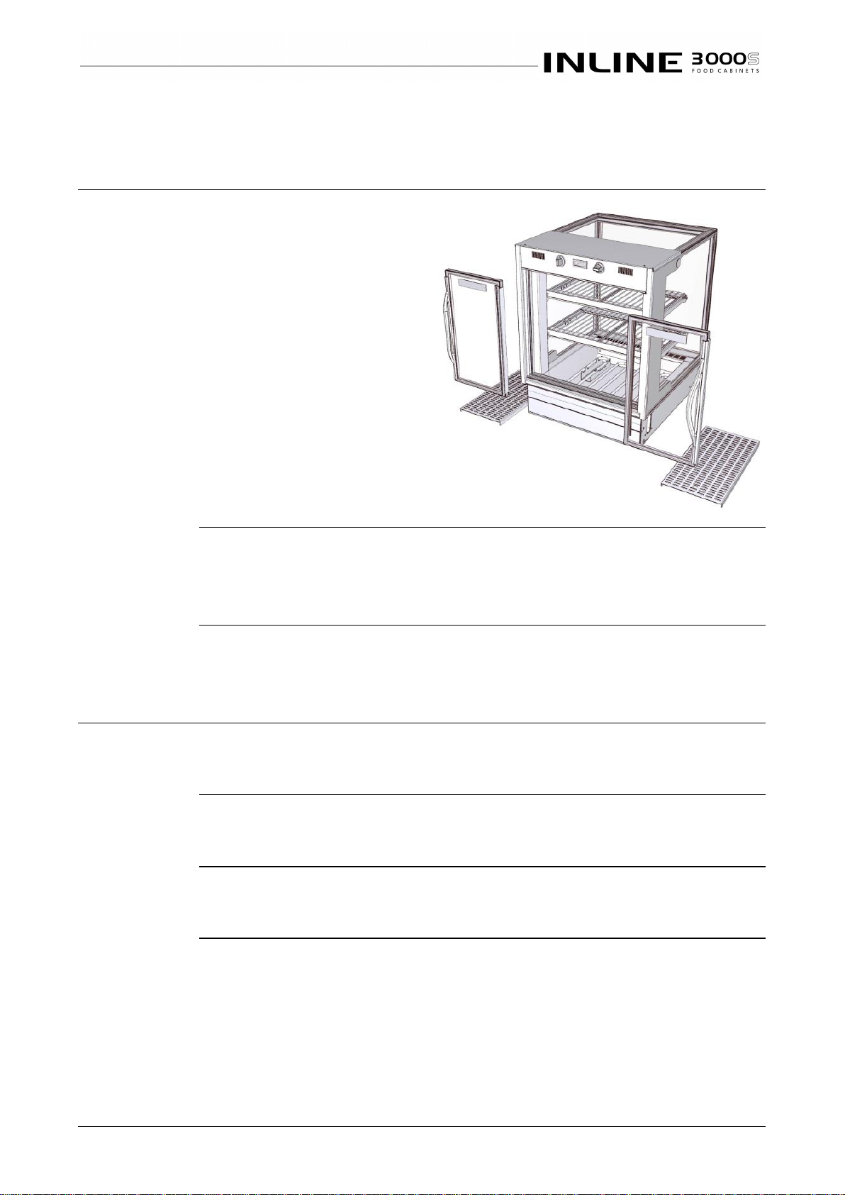
To clean the cabinet well,
remove the doors and lift out
the deck trays. Sweep out or
vacuum away any loose debris.
This cabinet is a dry well unit,
so the well is not waterproof.
Do NOT pour water into the
well as it will leak out and
damage insulation and
electrical wiring.
Trays, Racks,
Shelves & Air
Grills
Stainless steel trays, racks, shelves, grills etc. should be cleaned with hot soapy
water. Do not use abrasive pads or cleaners, as these may damage surfaces.
Warning: Dishwasher detergents will damage any anodised aluminium parts.
Routines
HEATED CABINETS
-
CLEANING
Schedules
To maintain optimum performance, cleaning schedules must be regular and
thorough.
Inspection
As part of the cleaning routine, the controls, mechanical parts and electrical
wiring should be inspected for damage, deterioration or need of adjustment.
Correction
If any small faults are found, have them attended to promptly by a competent
serviceman. Don’t wait until they cause a complete breakdown.
Page 14
Part No.26113 Rev. G September 2018 - 14 - Inline 3000 Square Series Cabinets
INSTALLATION
Regulations
HEATED CABINETS
-
INSTALLATION
Compliance
with Local
Requirements
It is very important that your inline food cabinet is installed correctly and that the
operation is correct before use. Installation must comply with local electrical,
health & safety and hygiene requirements.
Setting Up
HEATED CABINETS
-
INSTALLATION
Unpacking
Unpack and check unit for damage and report any damage to the carrier and
supplier. Report any deficiencies to your supplier.
The cabinet is supplied fully assembled, but the shelf trays are packed
separately.
Site
Preparation
Ensure the cabinet location and any bench cut outs are made to the precise
measurements shown in the Mechanical Drawings. Position the cabinet in its
allocated working position. Use a spirit level to ensure the cabinet is level from
side to side and front to back.
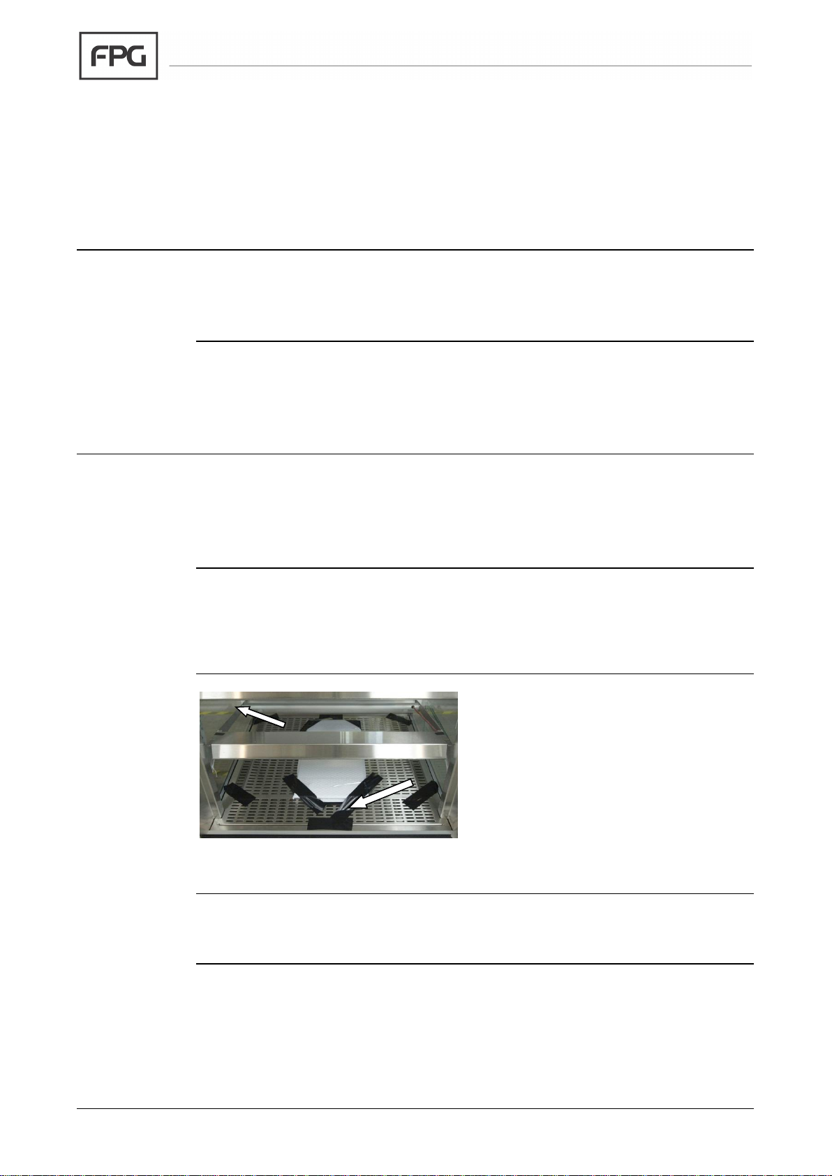
Cabinet
Preparation
Remove all tapes, ties and packers,
used to prevent movement during
transit.
Lift out the deck trays, grills and divider
bars, to gain access to the cabinet well.
Check that all plastic film protection has
been removed from surfaces; otherwise
it will melt when the cabinet heats up.
Re-assemble the trays and shelves.
Shelf Trays
Remove the shelf trays from their packing, peel off any protective plastic coating
and assemble them on the support members.
Continued on next page
Page 15
IN 3H06/09/12/15 - 15 - © Future Products Group
Setting Up cont.
HEATED CABINETS - INSTALLATION
Grounding
WARNING: THIS APPLIANCE MUST BE GROUNDED TO EARTH
The grounding lead, in the mains cable, must always be connected to ground.
A binding post is also provided adjacent to the control gear chassis, to allow the
cabinet to be bonded to a surge grounding conductor or to adjacent equipment,
should this be required.
Power Supply
Before connecting to the power supply, check that the local supply is correct to
that shown on the rating plate, located on the rear of the cabinet.
Isolation
If the cabinet is not connected by a plug and socket, but is hard wired to the
mains supply, a means of isolation must be provided.
If a plug and socket are used, they should still be accessible after the cabinet is
installed.
Location
HEATED CABINETS
-
INSTALLATION
Ventilation
The heated cabinet is designed to meet the HACCP specification with free room
air circulation.
Access
Access to the back of the cabinet is required for loading, cleaning, re-positioning
of shelves and operation of the control panel.
Fumes and
Odours
Before use, operate the cabinet for 4 hours at 90°C, to remove any fumes or
odours, which may be present. Open the doors periodically during this period,
to allow a change of air. This will avoid possible tainting of food.
Page 16
Part No.26113 Rev. G September 2018 - 16 - Inline 3000 Square Series Cabinets
SERVICING
Control Gear
HEATED CABINETS
-
SERVICING
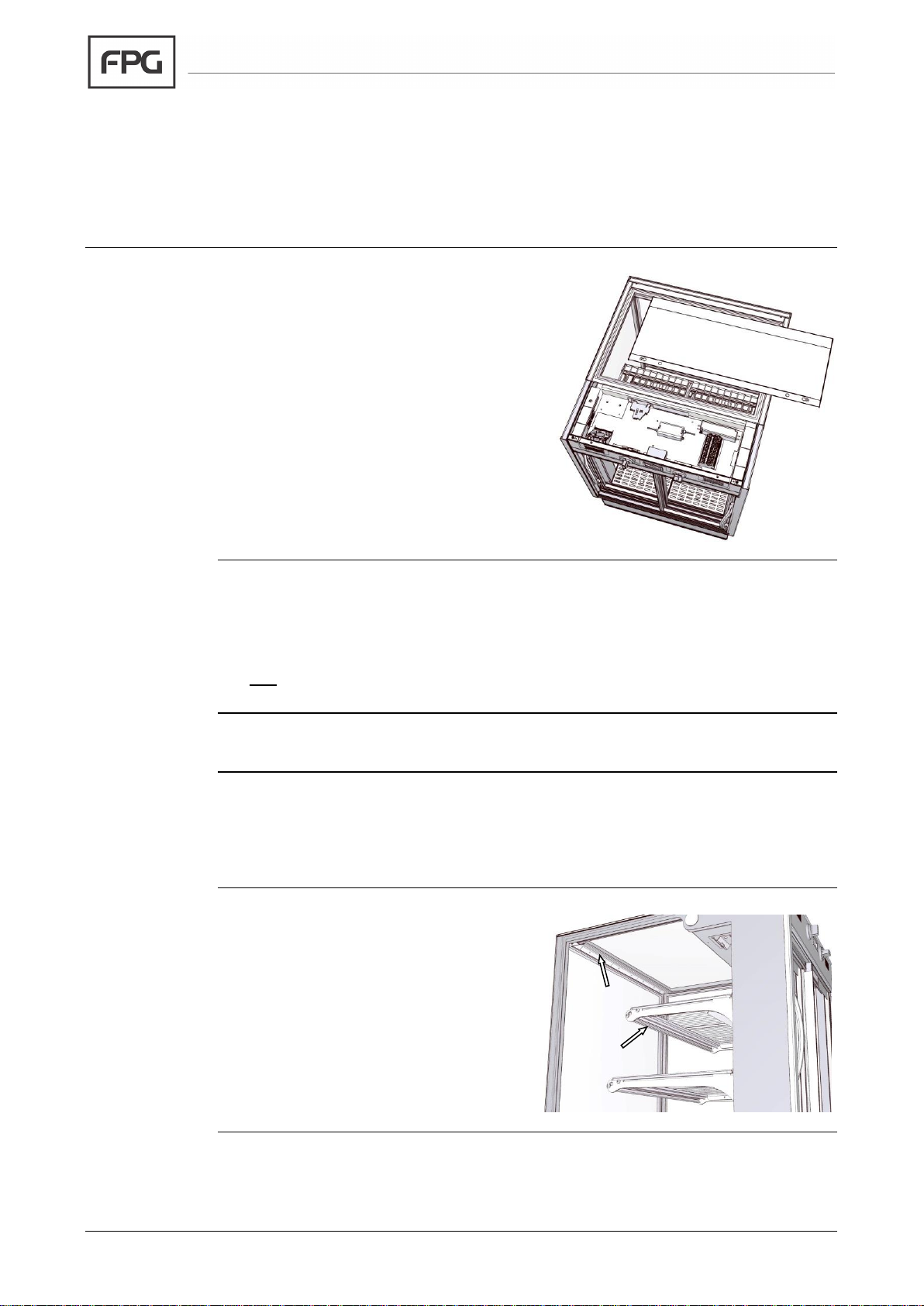
Location
The electrical control gear is located in the
top of the cabinet.
Remove the top plate to access the
control gear.
The chassis has a light switch, power
supplies for the lights and fan, a
thermostat, a thermometer, a ventilation
fan and a protective fuse.
Lighting
HEATED CABINETS
-
SERVICING
Caution
Do not service lights without isolating the cabinet from the mains supply.
Shelf Lights
Shelf lights are an optional extra, which can be fitted during manufacture.
Test Lighting
Components
Before replacing an LED strip, check that the power supply is working.
If there is no dc voltage at the output, the power supply should be replaced.
If there is a dc output, the LED strip must be replaced.
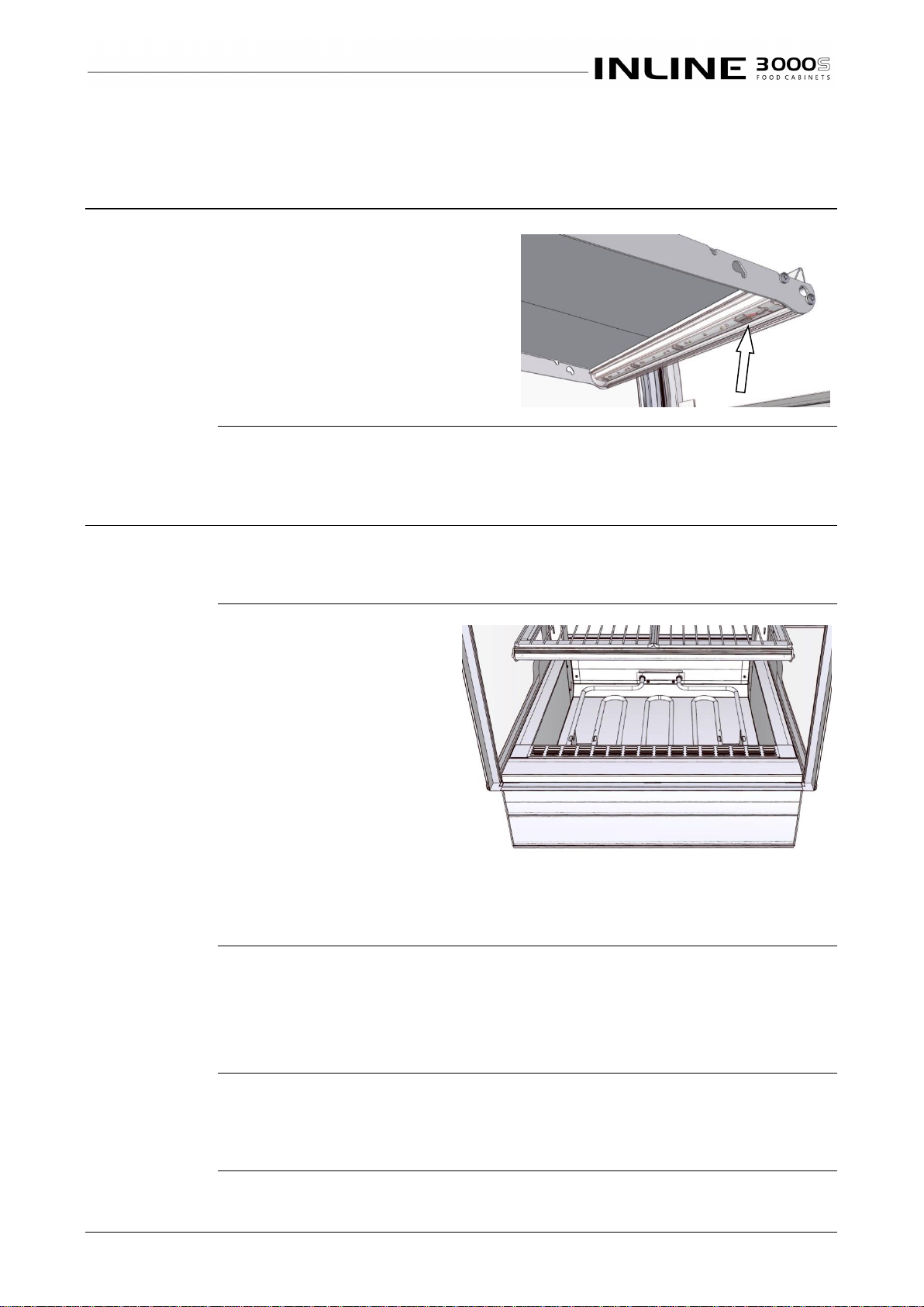
Access to LED
Strips
The LED strips are protected with
plastic covers. These clip into grooves
in the aluminium extrusion.
Remove the plastic cover to access the
LED strip.
The top light assembly is different from
the shelf lights, so the correct
replacement unit must be used.
Continued on next page
Page 17
IN 3H06/09/12/15 - 17 - © Future Products Group
Lighting cont.
HEATED CABINETS - SERVICING
LED Strip
Replacement
Individual LED modules cannot be
replaced. A complete light unit must
be used.
Connection is made with a plug and
socket. Disengage the supply lead
from the metalwork, and re-assemble
it to the replacement unit.
Heating
HEATED CABINETS
-
SERVICING
Caution
DO NOT attempt to replace heating elements without isolating the cabinet
at the supply switch or by unplugging it from the mains supply.
Element
Replacement
CAUTION:
This must only
be carried out by
a qualified
service person.
Remove the doors and base
trays from the cabinet, to
reveal the heating elements.
To access the element
terminals, remove the screws
securing the element to the
rear bulkhead. Unclip the
element from its support
brackets and withdraw it to
reveal the connections.
Disconnect the old element, connect the replacement, taking care to replace
and refit any insulation material. Position the new element against the
bulkhead, clip it into the support brackets and replace the two fixing screws.
Test
Turn the power on and test the heating operation. If the heating is now working,
replace the steel connection covers and re-assemble the base trays and doors.
If normal operation cannot be restored, by replacing the element, other circuit
elements will have to be checked, see Fault Finding.
Caution
Do not run the cabinet heaters for extended periods, without the base
trays in position. Directly radiated heat may otherwise damage the lower
light fittings.
Page 18
Part No.26113 Rev. G September 2018 - 18 - Inline 3000 Square Series Cabinets
Door Seals
HEATED CABINETS
-
SERVICING
Seal
Replacement
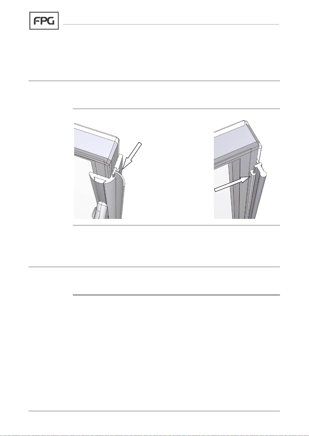
The doors should be removed to allow the old seals to be removed and the new
ones fitted. See the Cleaning section for details.
Sliding Doors
Each sliding door has a
rubber seal between the
door and the cabinet end
panel. The seal slides
into a groove in the door
extrusion, and can be
withdrawn and replaced,
if damaged.
A centre seal is fitted
between the inner and
outer doors. The Qlon
seal is located in a slot in
the aluminium extrusion,
and can be replaced if
damaged.
Mains Lead
HEATED CABINETS
-
SERVICING
Lead
Replacement
If damaged, the mains lead must ONLY be replaced by a qualified service
person.
Page 19

IN 3H06/09/12/15 - 19 - © Future Products Group
SPECIFICATIONS
Mechanical
HEATED CABINETS
-
SPECIFICATIONS
CABINET MODEL
IN 3H06S
IN 3H09S
IN 3H12S
IN 3H15S
Height (Counter Top)
781 mm
781 mm
781 mm
781 mm
Height (In Counter)
621 mm
621 mm
621 mm
621 mm
Height (Free Standing)
1272 (-0+30) mm
1272 (-0+30) mm
1272 (-0+30) mm
1272 (-0+30) mm
Width
600 mm
900 mm
1200 mm
1500 mm
Depth
662 mm
662 mm
662 mm
662 mm
Dry Weight
Cabinet Well Material
Stainless steel
Cabinet Colour
Grey, stainless steel and natural anodised aluminium.
Top Lighting
Standard
Shelf Lighting
Optional
Glass Type
Double Glazed and Toughened
Rear doors
Sliding glass
Cabinet front
Fixed glass
Number of Shelves
Two plus base
Display Area
0.56 m2
0.88 m2
1.2 m2
1.65 m2
Climatic Class & IP
Cabinets are tested under Climate Class 2 conditions and have IP 20 ratings
Electrical
HEATED CABINETS
-
SPECIFICATIONS
CABINET MODEL
IN 3H06S
IN 3H09S
IN 3H12S
IN 3H15S
Voltage
220 - 240 V 50 Hz 1
Power (with shelf lights)
870 W
881 W
1.64 kW
1.75 kW
Current (with shelf lights)
3.7 A
3.8 A
7.1 A
7.6A
Connection
3 pin plug, 10 A lead
HACCP Temp. Range
65 - 80 C
65 - 80 C
65 - 80 C
65 - 80 C
Max. Temp. Range
30 - 90 C
30 - 90 C
30 - 90 C
30 - 90 C
Top Lights
1 x LED strip
1 x LED strip
1 x LED strip
1 x LED strip
Optional Shelf Lights
2 x LED strips
2 x LED strips
2 x LED strips
2 x LED strips
Page 20
Part No.26113 Rev. G September 2018 - 20 - Inline 3000 Square Series Cabinets
Compliance
HEATED CABINETS
-
SPECIFICATIONS
Standards
FPG heated food display cabinets are designed to meet and exceed:
• International safety standards for electrical heated appliances: IEC 60335-1,
IEC 60335-2-49, IEC 60335-2-50 and the equivalent country-specific
standards including AS/NZS and BS EN.
• International standards for electromagnetic compatibility/emissions: CISPR
14-1, and the equivalent county-specific standards including AS/NZS CISPR
and BS EN 55014-1.
• Essential safety requirements: AS/NZS 3820 and AS/NZS 4417
Please contact FPG to discuss your requirements for meeting country-specific
standards.
Performance
Aspects
The cabinet is HACCP compliant, with the following performance:
Cabinet Operating Temperature
Test Conditions
>65°C
22°C Ambient with 65% RH
Operational
Safety
This appliance is not intended for use by young children or infirm persons,
unless they have been adequately supervised by a responsible person, to
ensure that they can use the appliance safely.
Young children should be supervised, to ensure that they do not play with the
appliance.
Improvements
HEATED CABINETS
-
SPECIFICATIONS
Ongoing
Development
FPG reserves the right to change specifications and construction, as part of
ongoing product improvement.
Page 21
IN 3H06/09/12/15 - 21 - © Future Products Group
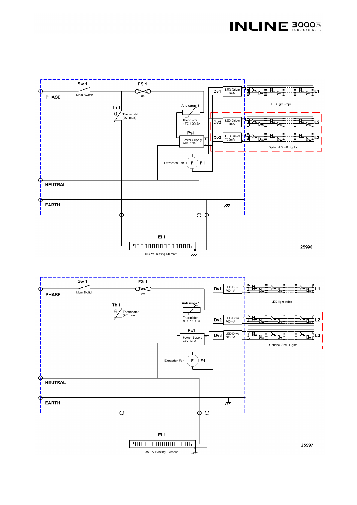
ELECTRICAL CIRCUIT DIAGRAMS
Model: IN 3H06-SQ
Inline 3000 Square Series, 600mm Heated Cabinet
Model: IN 3H09-SQ
Inline 3000 Square Series, 900mm Heated Cabinet
Page 22
Part No.26113 Rev. G September 2018 - 22 - Inline 3000 Square Series Cabinets
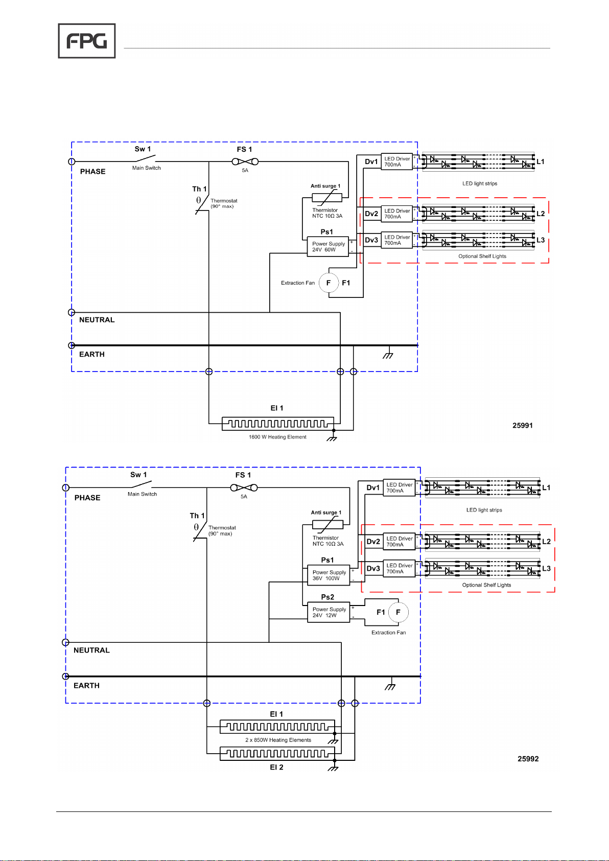
Model: IN 3H12-SQ
Inline 3000 Square Series, 1200mm Heated Cabinet
Model: IN 3H15-SQ
Inline 3000 Square Series, 1500mm Heated Cabinet
Page 23
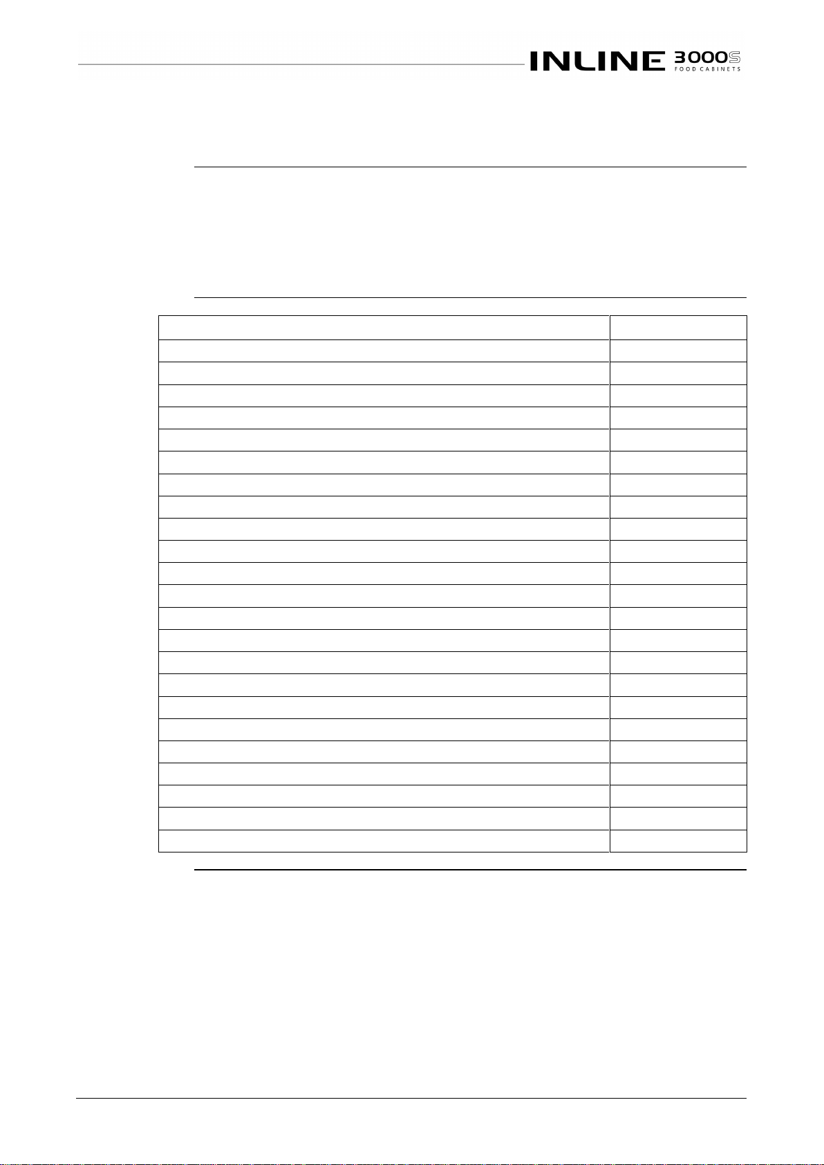
IN 3H06/09/12/15 - 23 - © Future Products Group
SPARE PARTS
Cabinet Serial
Number
When ordering spare parts, it is important to quote the Serial Number printed on
the label fixed to the control panel. This will enable FPG to ensure that spare
parts are fully compatible with your cabinet.
To satisfy warranty conditions, and ensure optimum performance, use
only FPG supplied spare parts.
Part Description
FPG Part No.
Main Switch EGO
14372
Knob (main switch)
14374
24V 60W LED power supply
21613
36V 100W LED power supply
25922
24V 12W Fan power supply
25184
LED Driver 700mA
25762
Polycarbonate Light Cover 1120mm
18113
Polycarbonate Light Cover 720mm
18114
Top Light Replacement Kit for 3H06 (Sliding Door / Fixed Front)
69964 / 69862
Shelf Light Replacement Kit for 3H06
70321
Top Light Replacement Kit for 3H09 (Sliding Door / Fixed Front)
70357 / 69861
Shelf Light Replacement Kit for 3H09
69402
Top Light Replacement Kit for 3H12
70378
Shelf Light Replacement Kit for 3H12
70380
Top Light Replacement Kit for 3H15 (Sliding Door / Fixed Front)
70382 / 70381
Shelf Light Replacement Kit for 3H15
70383
Ant-surge Thermistor 10 Ohm 3A
22354
Thermostat 90°C
21112
Thermostat Knob 40mm dia. 90°C
21113
Thermometer
11925
Heating Element 850W
23989
Heating Element 1600W
20779
Extraction Fan BLDC 60mm 24V dc
23282
Continued on next page
Page 24
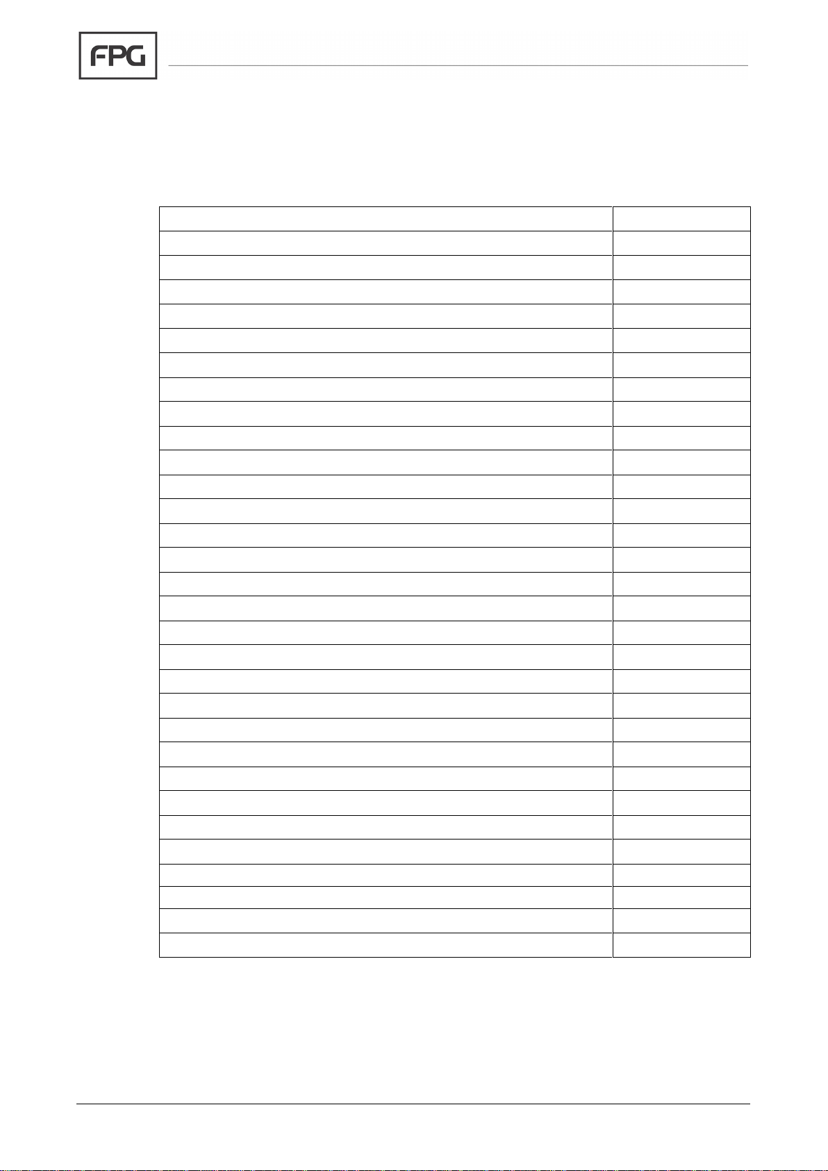
Part No.26113 Rev. G September 2018 - 24 - Inline 3000 Square Series Cabinets
Spare Parts Continued
Part Description
FPG Part No.
All glass parts are double glazed
LH & RH End Glass Kit
25139
Front fixed glass (600)
25140
Top glass (600)
25149
Rear Inner Sliding Door (600)
69165
Rear Outer Sliding Door (600)
69166
Front Inner Sliding Door (600)
69167
Front Outer Sliding Door (600)
69168
Front fixed glass (900)
25141
Top glass (900)
25150
Rear Inner Sliding Door (900)
69407
Rear Outer Sliding Door (900)
69408
Front Inner Sliding Door (900)
69844
Front Outer Sliding Door (900)
69032
Front fixed glass (1200)
25142
Top glass (1200)
25151
Rear Inner Sliding Door (1200)
69018
Rear Outer Sliding Door (1200)
69019
Front Inner Sliding Door (1200)
73488
Front Outer Sliding Door (1200)
73489
Front fixed glass (1500)
25593
Top glass (1500)
25594
Rear Inner Sliding Door (1500)
73494
Rear Outer Sliding Door (1500)
73495
Front Inner Sliding Door (1500)
73492
Front Outer Sliding Door (1500)
73493
Slide-in rubber door seal
11424
Qlon door seal
12922
Product Manual for Inline 3000 Square Series Heated Cabinets
26113
Page 25
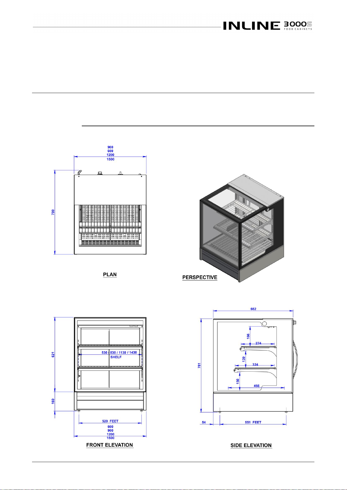
IN 3H06/09/12/15 - 25 - © Future Products Group
MECHANICAL DRAWINGS
Dimensions
HEATED CABINETS
-
MECHANICAL DRAWINGS
Cabinet
Variants
Sliding doors can be fitted to the front and back of the cabinets.
Fixed glass can be fitted in place of doors at the front.
IN 3H06/09/12/15-SQ Counter Top Mounting
Page 26
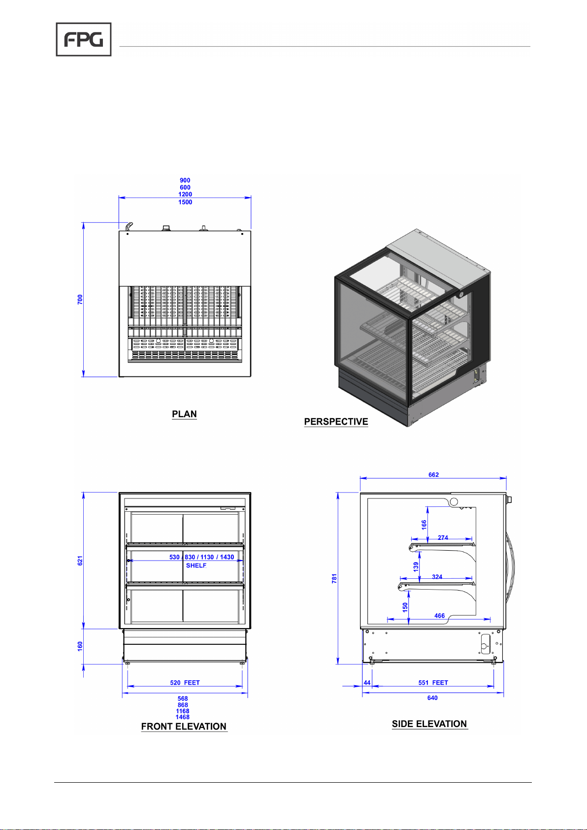
Part No.26113 Rev. G September 2018 - 26 - Inline 3000 Square Series Cabinets
IN 3H06/09/12/15-SQ In Counter Mounting
Page 27
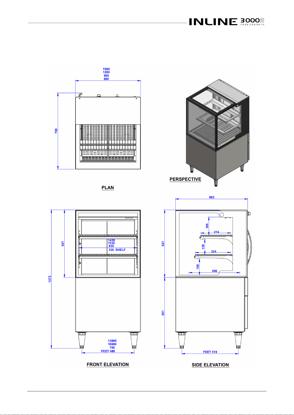
IN 3H06/09/12/15 - 27 - © Future Products Group
IN 3H06/09/12/15-SQ Free Standing
Page 28

Part No.26113 Rev. G September 2018
For full contact details please visit the Contacts page on FPGWORLD.COM or email us at [email protected]
In line with policy to continually develop and improve its products, Future Products Group reserves the right to change specifications and design without notice.
AUSTRALIA
E [email protected]
T 1800 813 745
INDIA
INDONESIA
UAE
NEW ZEALAND
UNITED KINGDOM
 Loading...