

Page 1

optimail
Postage meter
Installation Guide
Page 2
optimail Installation Guide
2
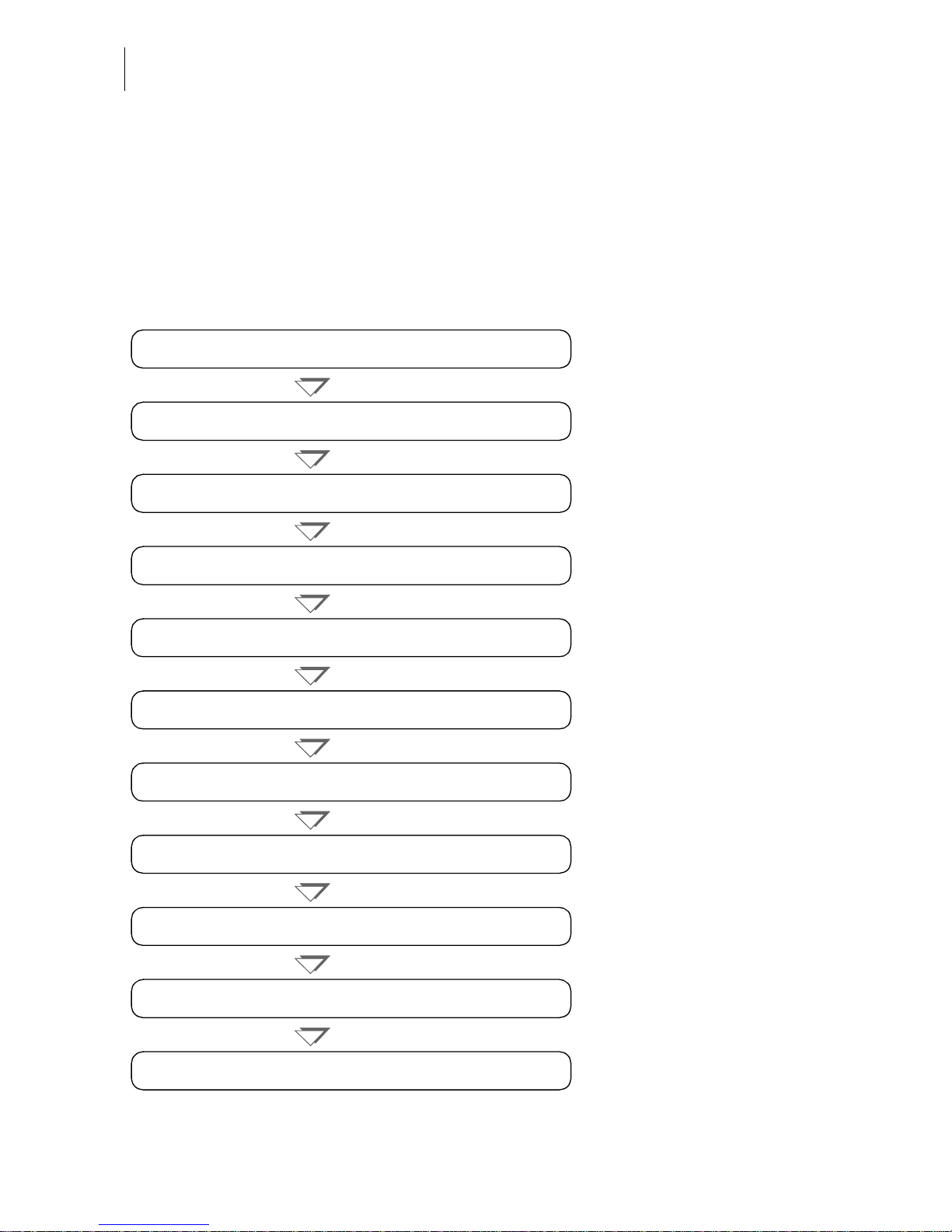
Commissioning overview
The following overview lists the operating steps for using your optimail for the first
time. You have to perform these steps in the given order before you can use the
optimail. If certain steps are inapplicable for installation and commissioning of your
optimail (e.g. because you have not ordered a sealer) simply proceed with the next
one. All steps are described in detail on the following pages.
Step 1: Unpacking
Step 2: Checking the contents of the package
Step 3: Installing the optimail
Step 5: Mounting the scale platform
(optional)
Step 8: Connecting the optimail
Step 9: Turning on
Step 11: Loading postage / TELESET
Step 4: Installing the ribbon cassette
Step 7: Installing the sealer
(optional)
Step 10: Authorization
Step 6: Installing the catch tray
(optional)
Page 3

Contents
3
Contents
Commissioning overview __________________________________________ 2
Safety tips ______________________________________________________ 4
Installing and commissioning optimail _______________________________ 5
Step 1: Unpacking __________________________________________5
Step 2: Checking the contents of the package ____________________6
Step 3: Installing the optimail __________________________________7
Step 4: Installing the ribbon cassette ____________________________7
Step 5: Mounting the scale platform
(optional)
______________________9
Step 6: Installing the catch tray
(optional)
________________________10
Step 7: Installing the sealer
(optional)
___________________________11
Step 8: Connecting the optimail _______________________________13
Step 9: Turning on ____________________ ______________ ___ __ __15
Step 10: Authorization _______________________________________16
Step 11: Loading postage / TELESET ___________________________22
Zero-rated postal imprint _________________________________________ 25
Tips for dealing with issues occurring during commissioning __________ 26
Service ________________________________________________________ 31
The optimail is desi gned so that you can install and start it yourself with the hel p
of this Installation Guide.
We will gladly provide support for installing your optimail. Simply contact our
service or your local sales agent.
Page 4

optimail Installation Guide
4
Safety tips
Please observe the following tips when installing and commissioning for your own
safety:
• Install and commission the optimail according to the instructions in this guide.
• Check that the machine is complete and undamaged. Do not start operating the
optimail if parts are damaged or missing. Please contact the Francotyp-Postalia
Service.
• Use only the power and modem cables provided or approved by FrancotypPostalia. Make sure that cables are not damaged.
• When you move the optimail from a cold environment (i.e. below 50°F / 10°C):
Wait at least 24 hours before connecting the optimail. The optimail requires this
period to adapt to the ambient conditions.
• Only operate t he optima il on a gr ounded s ingle-pha se power socket that c onforms
to the power requirements indicated on the serial number plate.
• Make sure the soc ket for c onnectin g the optimai l is close by and ea si ly acces sible
at all times.
• Do not remove any parts of the housing.
• Never cover the ventilat ion slots i n the housing.
• We recommend to use only approved FP equipment and FP original parts.
The manufacturer FP has established reliability, safety and applicability.
The manufacturer canno t assess the reliability , safety and applicability for pro ducts
not approved by FP, and therefore not vouch for such products.
• If you are using an external Francotyp-Postalia communication device
(GSM Modem or Universal Link Box) for optimail: carefully read the product
information that came with the GSM Modem / the Universal Link Box.
This Installation Guide exclusively describes the installation and commissioning
of the optimail postage meter. Please read the Operator Manual for further
information about optimail.
Page 5

Installing and commissioning optimail
5
Installing and commissioning optimail
Step 1: Unpacking
Postage meter
• Open the top of the box.
• Remove the accessories box from the
packing.
• Remove the upper packing shell.
• Remove the catch tray
(optional)
from the
packing.
• Carefully lift the o ptimail out of the packin g.
• Take optimail out of the plastic bag.
• Remove the p rotective foi l from the disp lay.
• Unpack the accessories.
Sealer (optional)
• Open the cardboard box.
• Take the sealer out of the cardboard box
and the plastic bag.
Keep the packing. Use it again when you
need to transport the optimail or send it in to
Service.
Page 6

optimail Installation Guide
6
Step 2: Checking the contents of the package
Warning! Do not st art opera ting th e opti mail
if parts are damaged or missing. Please
contact the Francotyp-Postalia Service.
• Check that the cont ents of the package are
complete and free from any damage.
Scope of delivery (standard variant): Optional, as ordered:
1 optimail postage meter 7 Catch tray with stop
2 Power cable 8 USER card
3 Modem cable 9 Data card(s) as ordered
4 Ribbon cassette 10 Sealer
5 MASTER card 11 Scale (mounted to postage
meter) and scale platform
6 Operator Manual
Installation Guide
Quick Reference Guide
GSM Modem
(not shown)
Universal Link Box
(not shown)
1
2
3
457
8
9
10
11
6
Page 7
Installing and commissioning optimail
7
Step 3: Installing the optimail
Caution! Wh en you move the opti mail from a
cold environment (i.e. below 50°F / 10°C):
Wait at least 24 ho urs be fore c on nectin g the
optimail. The optimail requires this period to
adapt to the ambient conditions.
• Choose an installation site with the
following ambient conditions:
– Room temperature: 50°F (10°C) to
104°F (40°C).
– No direct sunlight.
– Power socket and telephone jack for
connecting th e mo dem i n the imm ediate
vicinity.
• Place the optimail on a firm, level, low
vibration and horizontal base.
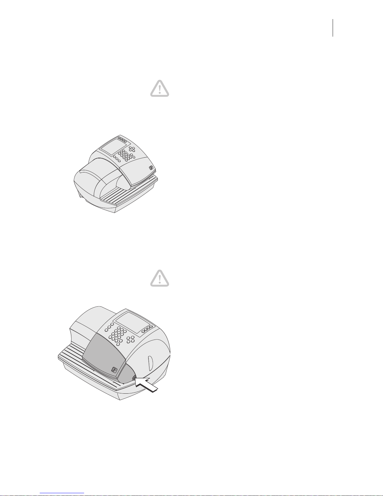
Step 4: Installing the ribbon cassette
Caution! Make sure not to crease or tear the
ribbon when inserti ng it. Otherwise the ribbon
might break.
Also make sure the edges of the ribbon do
not fold over. F old ed rib bon s are thicker and
prematurely fill the take-up ribbon spool.
• Open the flap of the ribbon cassette
compartment by lightly pressing the
release catch.
The flap swings up automatically to the stop.
Page 8
optimail Installation Guide
8
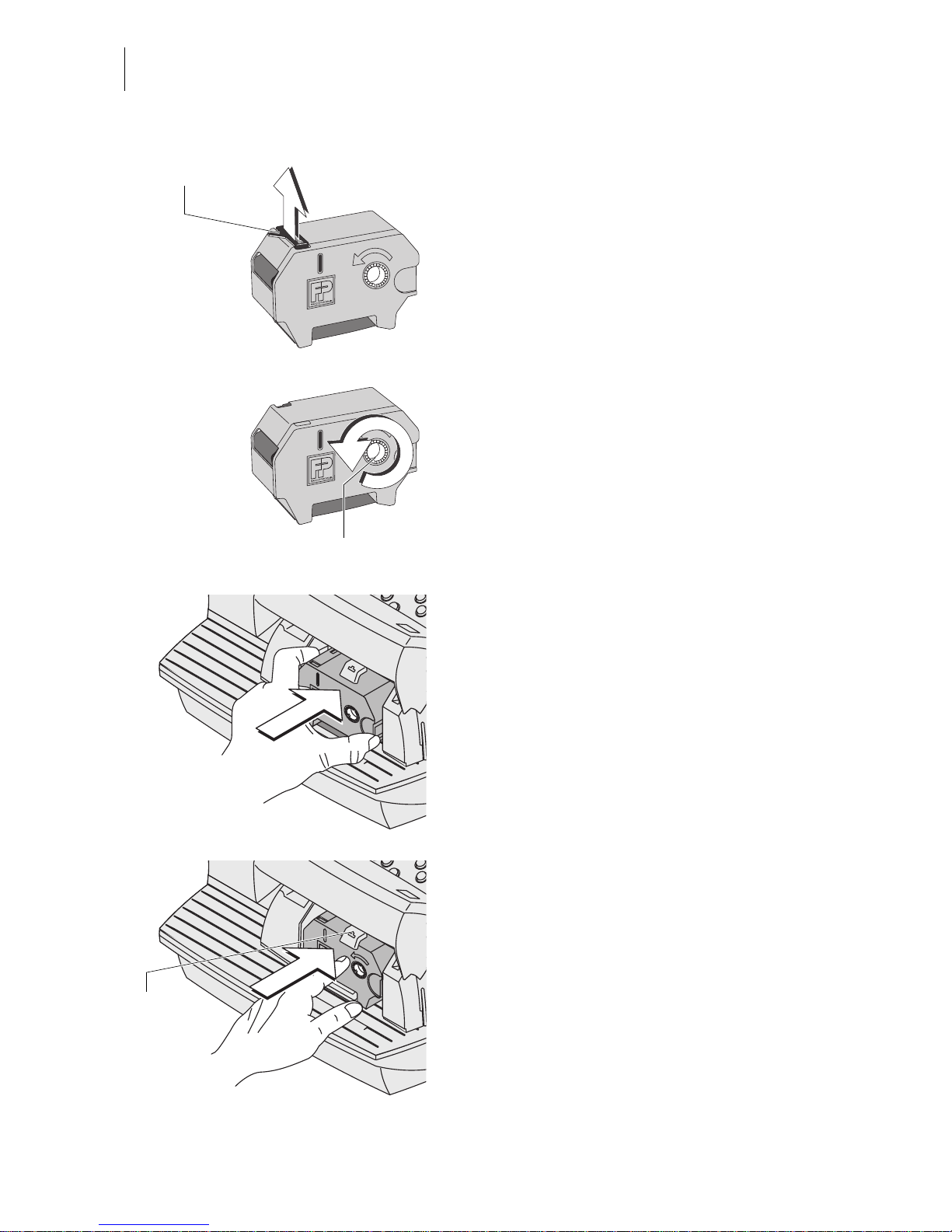
• Take the sup plied ribbon cassette fro m the
packing.
A cardboard strip may be present in the ribbon cassette as transport fixture (see the
illustration).
• If present: Remove the cardboard strip.
• Tension the ribbon. Turn the white ribbon
spool in the direction of the arrow.
• Place the ribbon cassette on the letter
receiving tray with the ribbon facing
downwards.
• Hold the ribbon cassette as shown in the
illustration and carefully insert it in the
cassette slot. The cassette must easily
slide into the cassette slot.
• Insert the cas sette until the l atch s na ps in .
Transport fixture
(cardboard strip)
Ribbon spool
Cassette
latch
Page 9
Installing and commissioning optimail
9
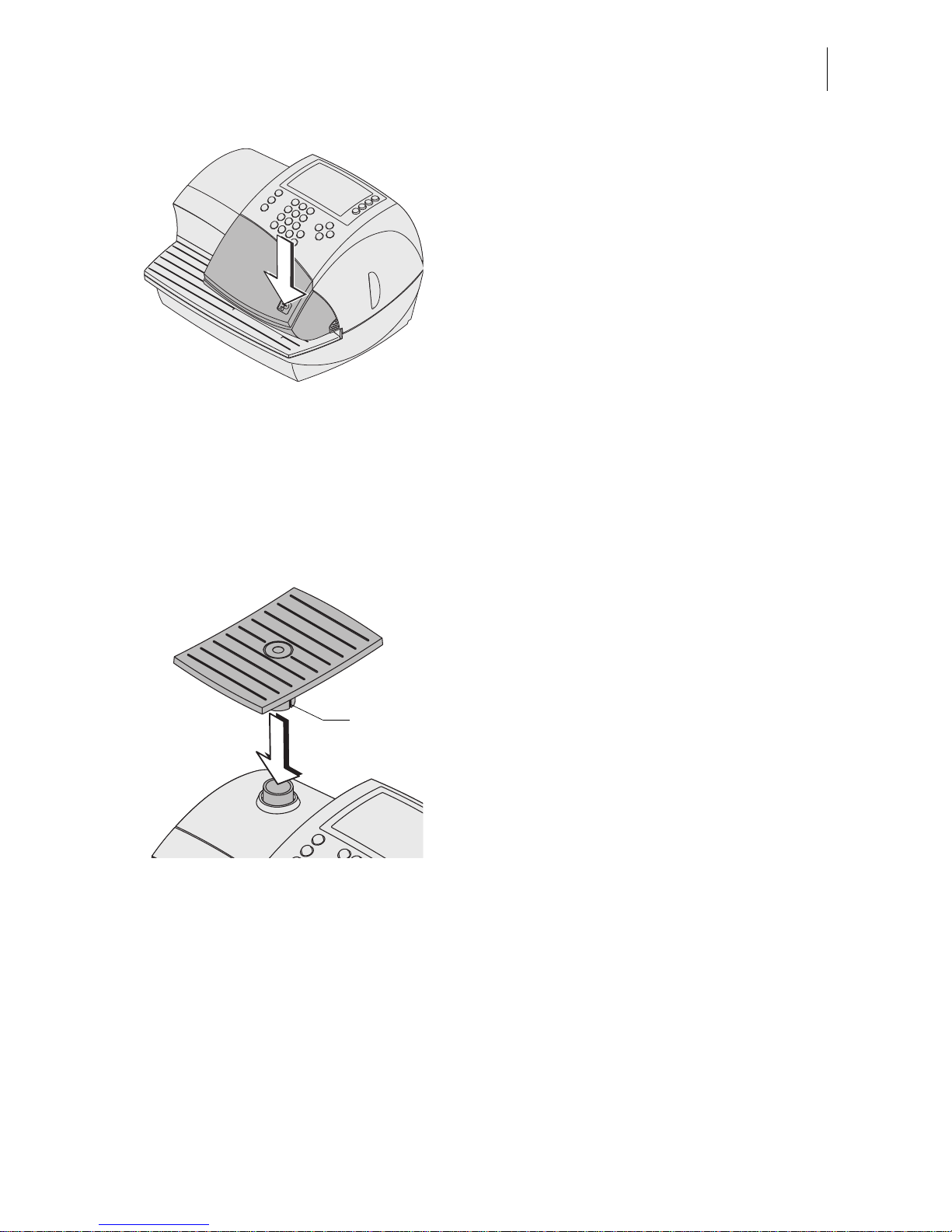
• Close the cover. You can feel the lock snap
in.
Step 5: Mounting the scale platform
(optional, otherwise continue with Step 6)
If you ordered an optimail with integrated
scale, the scale comes mounted to the
postage meter on delivery. You need only
attach the scale platform.
• Hold the scale platform so that the long slot
in the scale pl atform foot points to the right
(towards the display).
• Place the scale platform onto the scale
receptacle from abo ve. The long slot of the
scale platform must slide in t he counterpart
on the scale receptacle.
• Press down slightly on the scale platform
with your flat hand.
Slot, long
Page 10
optimail Installation Guide
10
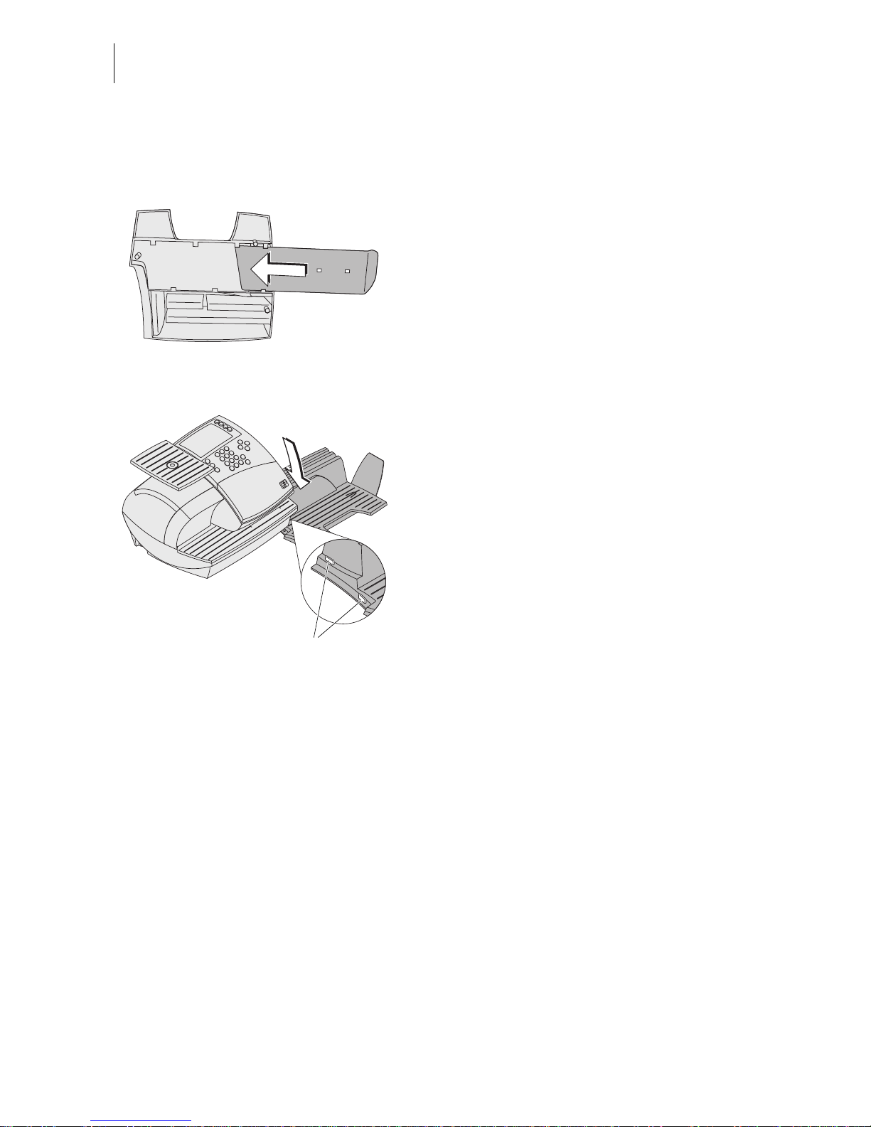
Step 6: Installing the catch tray
(optional, as ordered, otherwise continue with Step 7)
• Attach the stop to the catch tray:
Slide the stop into t he gu id es o n the catch
tray bottom.
• Place the catch tray to the right of the
postage meter.
• Slightly lift the postage meter on the right.
The right side of the housing features two
slots where the catch tray is fastened.
• Push the catch tray underneath the
postage meter so that the catches on the
catch tray engage in the slots.
• Put the postage meter carefully down.
Catches
Page 11

Installing and commissioning optimail
11
Step 7: Installing the sealer
(optional, as ordered, otherwise continue with Step 8)
Filling the sealer
• Swing up the rocker with the moistening
felt.
The filler hole for topp ing up the sealer is now
accessible.
• Fill the sealer with tap water or sealing
liquid. The special sealing liquid is
available from Francotyp-Postalia.
• Check the liquid level.
The liquid le vel in the sea ler should rough ly
reach to the ‘Max’ mark.
• Swing down the rocker.
• If necessary: dry the sealer outside.
Rocker with
moistening felt
Filler hole
Liquid level gauge
Page 12

optimail Installation Guide
12
Connecting the sealer to the postage
meter
• Place the sealer to the left of the postage
meter.
• Slightly lift the postage meter on the left.
The left side of th e housing features tw o
slots where the sealer is fastened.
• Push the sealer underneath the postage
meter such that b oth catches on the sealer
engage in the slots.
• Put the postage meter carefully down.
Catches
Page 13

Installing and commissioning optimail
13
Step 8: Connecting the optimail
Warning! Use only the power and modem
cables provide d with the optimail or app roved
by Francotyp-Postalia.
Make sure that cables are not damaged.
Connect the optimail only to a grounded
single-phase power socket. Make sure your
office power supply conforms to the power
requirements shown on the optimail’s serial
number plate.
Make sure the socket for connecting the
optimail is close by and easily accessible at
all times.
If you are using the internal modem:
• Plug the modem cable into the modem
socket on the postage meter. The modem
socket is at the rear of the postage meter.
The spring on the plug must face
downwards.
• Connect the modem cable to the telep hone
socket (analog). This is where you would
connect a fax machine.
If you are using the GSM Modem
(optional)
:
• Set up the GSM Modem according to the
enclosed manual.
• Plug the connection cable to the serial
interface of optimail and to the GSM
Modem.
• Plug the AC adapter of the GSM Modem
into a grounded single-phase power
socket.
Make sure your office power supply conforms to power requ irements shown o n the
AC adapter’s serial number plate.
Modem cable
Connection cable
Power connection
Antenna terminal
Page 14

optimail Installation Guide
14
If you are using the Universal Link Box:
(optional)
• Set up the Universal Link Box (ULB)
according to the enclosed manual.
• Use the adapter (D-Sub, 9-pin male / 25pin male) to plug the connection cable to
the serial interface of optima il.
• Plug the AC adapter of the ULB into a
grounded single-phase power socket.
Make sure your office power supply conforms to powe r requirements sh own on the
AC adapter’s serial number plate.
Power cable
• Connect the power cable to the postage
meter. The powe r connecti on is at the rear
of the optimail.
• Plug the power plug into a grounded
single-phase power socket.
Make sure your office power supply conforms to powe r requirements sh own on the
serial number plate of the optimail.
Connection cable
Network cable
Power connection
(AC adapter)
Adapter
Power cable
Page 15

Installing and commissioning optimail
15
Step 9: Turning on
• Push I (= ON) on the power switch, the
toggle switch on the left side of the posta ge
meter.
The display lights up and the authorization
procedure starts.
Page 16

optimail Installation Guide
16
Step 10: Authorization
A Security Device protects the optimail against manipulation. This Security Device
monitors the statu s of the postage meter. This is why you must first sig n in (authorize)
at the TELESET data center and load postage (validate). The optimail guides you
through this authorization procedure. Simply follow the instructions on the display.
Notes on the authorization procedure
The optimail caption indicates the current
step of the authorization procedure.
The left window area displays instructions
and current settings (display area).
The right window area (menu area) displays
the control functions for the authorization
procedure (CONTINUE, CANCEL…) and
various options, e.g. for modem
configuration.
Use the multi function keys – t he k ey s to t he
right of the display – to select the desired
setting / function.
Also heed the information in the status bar.
Inserting the MASTER card
• Insert the supplied card labeled MASTER
into the card reader on the righ t side of the
postage meter. The chip on the card must
face the rear.
• Push in the card a gainst a slight res istance
all the way to the stop. You will feel the card
snap in.
Caption
Menu area
(here still empty)
Display area
Status bar
Multi function keys
Page 17

Installing and commissioning optimail
17
• Press the CONTINUE multi function key.
Setting the location (province)
(only optimail with scale)
You must set the postage meter location if
you own an optimail with scale
. The optimail
needs this da ta to ex actly d isplay the weight .
The optimail opens a list.
• Use the arrow keys to scroll for the
appropriate province.
• Use the multi function keys to set the
province. In the example: ONTARIO.
The optimail sa ves this se tting and contin ues
with the next authorization procedure step –
Connection Configuration.
Connection Configuration
There are three ways of connecting optimail:
– Internal Modem
– GSM Modem
– Universal Link Box (ULB).
• Start Connection Configuration with
CONTINUE.
optimail sca ns c onnect ed de vices and offers
a list where you can select from available
connection types. This can take a few seconds.
Page 18

optimail Installation Guide
18
Connection Configuration:
Internal Modem
You must edit the configu ration to ma tch the
internal modem to your telephone c onnection
so the optimail c an est ablis h a conn ectio n to
the TELESET data center.
• Select INTERNAL MODEM.
The optimail prompts you for
– the connection type (phone type)
– the access method
– the exchange digit if applicable.
The table on page 19 show s and explains the
possible settings.
The TELESET data center number is stored
at the factory.
• Use the multi function keys to select the
desired settin g.
When the correct setting appears in the
display area:
• CONTINUE.
When finished the optimail displays the set
modem configuration.
If the modem parameters shown are correct:
• SAVE.
• Continue with “Authorization” on page 21.
Page 19

Installing and commissioning optimail
19
Modem parameters – possible settings and their meaning
Phone type DIRECT LINE optimail is connected to a main line.
EXTENSION optimail is connected to an extension.
Access method
(extension only)
EXCHANGE DIGIT Defines how the exchange is dialed
from the extension.
Usually you would choose EXCHAN GE
DIGIT.
The hook flash time of the internal
modem has been fixed to 500 ms.
HOOK FLASH
Exchange digit The exchange digit
depends on the
telephone sy ste m.
Use the numeric keys to type the
exchange digi t. The exchange di git can
comprise seve ral digits . Normally , a ‘0’
is used.
A W indicates w aiti ng
for the dialing t one.
Use WAIT to define waiting for the
dialing tone after the exchange digit
was dialed.
A comma (,) indica tes a
dialing pause.
Use PAUSE to inse rt a d ial ing de lay of
2 seconds.
Page 20

optimail Installation Guide
20
Connection Configuration:
GSM Modem
(optional)
To operate the GSM Modem you must type
the PIN of your modem’s SIM card.
• Select GSM MO D E M.
• Type the PIN (4 digits minimum, 8 digits
maximum).
• Press SAVE to confirm your input.
• Continue with “Authorization” on page 21.
Connection Configuration:
Universal Link Box
(optional)
You must configure the network connection
before optimail can establish a connection
with the TELESET data center.
• Have the Francotyp-Postalia customer
information with the data for your network
at hand. If necessary, co ntact your network
administrator.
• Select UNIVERSAL LINK BOX.
optimail will now try to establish a connectio n
with your network. A m essage will infor m you
of the test result.
• Follow the inst ructions on the display to
configure the network.
You will find ex ten si ve i nfo rma tio n ab out the
procedure of the network conf ig ura tion and
the explanation of technical terms and
abbreviations used in network installation
online at www.francotyp.com.
Page 21

Installing and commissioning optimail
21
Authorization
optimail will call the data center when
Connection Configuration has been
completed successfully.
It will take about 1 to 2 minutes to establish
the connection and to authorize your optimail. Please stand by.
The optimail displays a message when the
authorization was successful and prompts
you to load postage.
• Select CONTINUE to start the TELESET
process (Step 11).
Page 22

optimail Installation Guide
22
Step 11: Loading postage / TELESET
You now load th e first pos tage into your post age meter. The sum y ou enter is loaded
into your optimail as a postage credit. The called amount is paid according to your
contract with Francotyp-Postalia Canada Inc.
• Use CHANGE to open the menu for the
amount to be loaded.
• Type the desired amount.
• Continue with LOAD.
For verification the optimail displays the set
amount.
To load this amount:
• Use LOAD to establish the connection to
the TELESET data center.
Loading continues automatically. You can
monitor the progress in the display. Please
stand by. Data exchange takes some time
(2 - 3 min). If a new rate table is available, it
is automatically downloaded, increasing
download time by another 2 minutes.
The residual sum is indicated when loading
ends. This represents the available postage
credit of your optimail.
Page 23

Installing and commissioning optimail
23
Viewing and printing a report
• Use REPORT to view the loading report.
• Use the arrow keys to scroll throu gh
the report.
• Fold a sheet (le tter s iz e) do wn the mi ddl e.
• Place the folded sheet on the letter
receiving tray:
– side to be printed face up
– the folded edge must touch the letter
guide.
• Push the sheet in direction of the arrow
until the optimail feeds the sheet.
A roller pushes th e s he et aga ins t r ibb on and
print head and printing starts as soon as the
letter sensor detects the sheet.
The optimail prints the report and ejects the
imprinted sheet to the right.
• Press the key to exit the Report
function.
You can also print the report on an empty
envelope or a self-adhe sive FP double label .
Folded edge
Page 24

optimail Installation Guide
24
• Select CONTINUE to end the TELESET
process.
The optimail displays the home menu.
Installation is complete.
You received the adverts you ordered with
your optimail on chip card. Refer to the
Operator Manual for instructions on how to
load data from a chip card to the optimail.
Page 25

Zero-rated postal imprint
25
Zero-rated postal imprint
Your optimail is ready for operation when commissioning has been completed
successfully. We recommend that you make a trial run now.
• Press .
• Use the ar row key to scroll t o the n ext
page.
• Use the multi function keys to select:
IMPRINT MANAGEMENT ZERORATED POSTAL IMPRINT.
optimail sets the ‘Zero-R at ed P ost al Imp r int ’.
• Place an empty envelope or a folded sheet
on the letter catch tray:
– side to be printed face up
– the top edge must touch the letter guide.
• Push the envelop e in direction of the arro w
until the optimail feeds the envelope. The
illustration shows the approximate position
where the optimai l s tarts fe edi ng the letter.
A roller pushes the envelope against ribbon
and print head as soon as the letter sensor
detects the envelope. Printing starts. The
optimail prints and ejects the imprinted
envelope to the right.
The optimail prints a normal meter imprint
with the postage value ‘00.00’ (zero-rated
postal imprint).
End ‘Zero-Rated Postal Imprint’
• Keep the key pressed (approx. 2 seconds), until the display again shows the
symbol for product selection / setting the postage value in the top right.
Please read the Operator Manual for further
information on how to operate the optimail.
Page 26

optimail Installation Guide
26
Tips for dealing with issues occurring during
commissioning
Issue Possible cause and remedy
Authorization aborted An error message with troubleshooting information
appears in case of authorization issues.
If necessary:
• Turn off the optimail. Wait one minute.
• Turn the optimail on again.
The authorization proc edure rest arts.
Make sure that the Connection Configuration is set
correctly
(see page 17)
.
Blank display Check whether the power cab le is plugged in correctly
and the power switch is turned on.
Connection Conf igur ation:
GSM Modem cannot be
set up
optimail fails to detect the GSM Modem.
Turn off the optimail.
Check whether the GSM Modem has been installed
correctly and connected to optimail.
(See page 13 and the
product information that came with the GSM Modem.)
Turn on optimail again and restart Connection
Configuration.
If you cannot solve the problem: Call Service.
Connection Conf igur ation:
Universal Link Box cannot
be set up
optimail fails to detect the Universal Link Box.
Turn off the optimail.
Check whether the Universal Link Box has been
installed correctly and connected to optimail.
(See
page 14 and the product information that came with the ULB.)
Turn on optimail again and restart Connection
Configuration.
If you cannot solve the problem: Call Service.
Delivery is incomplete /
damaged
Do not start operating the optimail.
Call Service.
Page 27

Tips for dealing with issues occurring during commissioning
27
optimail does not
recognize the MASTER
or data cards
Card is insert ed incorrectly.
Remove the card. Insert the card in the card reader
again (chip facing the rear!).
The card contains no valid data. Insert a card with vali d
data.
Card is defective. Call Service.
TELESET aborted An error message with troubleshooting information
appears in case of TELESET procedure issues. You
must repeat the loading procedure before you can
start metering with the optimail. To do this:
•Press .
• Select TELESET.
Or
• Turn off the optimail. Wait one minute.
• Turn the optimail on again.
The optimail starts the loading procedure.
Please read the Operator Manual for further
information regarding the TELESET topic.
Other errors … See Operator Manual.
If you cannot remedy an error yourself, please call
Service.
Issue Possible cause and remedy
Page 28

optimail Installation Guide
28
Page 29

For your notes
29
Page 30

For your notes
30
Page 31

Service
31
Service
Francotyp-Postalia Canada Inc.
82 Corstate Ave.
Concord Ontario CAN - L4K 4X2
The Francotyp-Posta lia quality ma nagement
system for the scope Design and Manufacturing of Franking Machines and Inserters is
certified according to DIN EN ISO 9001.
Registration Number: DE-275570 QM
Page 32

51.0034.3084.00 Rev. 02
2010-05 / xxx / helbig berlin
 Loading...