

Page 1

1
NT415 EPB Service Tool Manual_English_V1.01
Trademarks
FOXWELL is trademark of Shenzhen Foxwell Technology Co., Ltd.
All other marks are trademarks or registered trademarks of their respective holders.
Copyright Information
© 2013 Shenzhen Foxwell Technology Co., Ltd.
All rights reserved.
Disclaimer
The information, specifications and illustrati ons in this manual are based on the latest information
available at the time of printing.
Foxwell reserves the right to make changes at any time without notice.
Visit our website at:
www.foxwelltech.com
For Technical Assistance, send us email at
PDFaid.Com
#1 Pdf Solutions
Page 2

2
NT415 EPB Service Tool Manual_English_V1.01
One-Year Limited Warranty
Subject to the conditions of this limited warranty, Shenzhen Foxwell Technology Co., Ltd
(“FOXWELL”) warrants its customer that this product is free of defects in material and
workmanship at the time of its original purchase for a subsequent period of one (1) year.
In the event this product fails to operate under normal use, during the warranty period, due to
defects in materials and workmanship, FOXWELL will, at its sole option, either repair or replace
the product in accordance with the terms and conditions stipulated herein.
Terms and Conditions
1 If FOXWELL repairs or replaces the product, the repaired or replaced product shall be
warranted for the remaining time of the original warranty period. No c harge will be made to the
customer for replacement parts or labor charges incurred by FOXWELL in repairing or replacing
the defective parts.
2 The customer shall have no coverage or benefits under this limited warranty if any of the
following conditions are applicable:
a) The product has been subjected to abnormal use, abnormal conditions, improper storage,
exposure to moisture or dampness, unauthorized modifications, unauthorized repair, misuse,
neglect, abuse, accident, alteration, improper installat ion, or other acts which are not the fault of
FOXWELL, including damage caused by shipping.
b) The Product has been damaged from external causes such as collision with an object, or from
fire, flooding, sand, dirt, windst orm, lightning, earthquake or damage from exposure to weather
conditions, an Act of God, or battery leakage, theft, blown fuse, improper use of any electrical
source, or the product was used in combination or connection with other product, attachments,
supplies or consumables not manufactured or distributed by FOXWELL.
3 The customer shall bear the cost of shipping the product to FOXWELL. And FOXWELL shall
bear the cost of shipping the product back to the customer after the completion of service under
this limited warranty.
4 FOXWELL does not warrant uninterrupted or error-free operation of the product. If a problem
develops during the limited warranty period, the consumer shall t ake the following step-by-step
procedure:
a) The customer shall return the product to the place of purchase for repair or replacement
processing, contact your local FOXWELL distributor or visit our website www.foxwelltech.com to
get further information.
b) The customer shall include a return address, daytime phone number and/or fax number,
complete description of the problem and original invoice specifying date of purchase and serial
number.
c) The customer will be billed for any parts or labor charges not covered by this limited warranty.
d) FOXWELL will repair the Product under the limited warranty withi n 30 days aft er receipt of the
product. If FOXWELL cannot perform repairs covered under this limited warranty within 30 days,
or after a reasonable number of attempts to repair the same defect, FOXWELL at its option, will
provide a replacement product or refund the purchase price of the product less a reasonable
amount for usage.
e) If the product is returned during the limited warranty period, but the problem with the product is
not covered under the terms and conditions of this limit ed warranty, the customer will be notif ied
and given an estimate of the charges the customer must pay to have the product repaired, with all
shipping charges billed to the customer. If the estimate is refused, the product will be returned
freight collect. If the product is returned after the expiration of the limited warranty period,
FOXWELL’ normal service policies shall apply and the customer will be responsible for all
shipping charges.
5 ANY IMPLIED WARRANTY OF MERCHANTABILITY, OR FITNESS FOR A PARTICULAR
PURPOSE OR USE, SHALL BE LIMITED TO THE DURATION OF THE FOREGOING LIMITED
WRITTEN WARRANTY. OTHERWISE, THE FOREGOING LIMITED WARRANTY IS THE
CONSUMER’S SOLE AND EXCLUSIVE REMEDY AND IS IN LIEU OF ALL OTHER
WARRANTIES, EXPRESS OR IMPLIED. FOXWELL SHALL NOT BE LIABLE FOR SPECIAL,
INCIDENTAL, PUNITIVE OR CONSEQUE NTIAL DAMAGES, INCLUDING BUT NOT LIMITED
Page 3

3
NT415 EPB Service Tool Manual_English_V1.01
TO LOSS OF ANTICIPATED BENEFITS OR PROFITS, LOSS OF SAVINGS OR REVENUE,
LOSS OF DATA, PUNITIVE DAMAGES, LOSS OF USE OF THE PRODUCT OR ANY
ASSOCIATED EQUIPMENT, COST OF CAPITAL, COST OF ANY SUBSTITUTE EQUIPMENT
OR FACILITIES, DOWNTIME, THE CLAIMS OF ANY THIRD PARTIES, INCLUDING
CUSTOMERS, AND INJURY TO PROPERTY, RESULTING FROM THE PURCHASE OR USE
OF THE PRODUCT OR ARISING FROM BREACH OF THE WARRANTY, BREACH OF
CONTRACT, NEGLIGENCE, STRICT TORT, OR ANY OTHER LEGAL OR EQUITABLE
THEORY, EVEN IF FOXWE LL KNEW OF T HE LIK ELIHOOD O F SUCH DAMAGES. FOXWELL
SHALL NOT BE LIABLE FOR DELAY IN RENDERING SERVICE UNDER THE LIMITED
WARRANTY, OR LOSS OF USE DURING THE PERIOD THAT THE PRODUCT IS BEING
REPAIRED.
6
Some states do not allow limitation of how long an implied warranty lasts, so the one-year
warranty limitation may not apply to you (the Consumer). Some states do not allow the exclusi on
or limitation of incidental and consequential damages, so certain of the above limitations or
exclusions may not apply to you (the Consumer). This limited warranty gives the Consumer
specific legal rights and the Consumer may also have other rights which vary from state to state.
Page 4

4
NT415 EPB Service Tool Manual_English_V1.01
Safety Information
For your own safety and the safety of others, and to prevent damage to the equipment and
vehicles, read this manual thoroughly before operating your EPB service tool. The safety
messages presented below and throughout this user’s manual are reminders to the operator to
exercise extreme care when using this device. Always refer to and follow safety messages and
test procedures provided by vehicle manufacturer. Read, understand and follow all safety
messages and instructions in this manual.
Safety Message Conventions Used
We provide safety messages to help prevent personal injury and equipment damage. Below are
signal words we used to indicate the hazard level in a condition.
Indicates an imminently hazardous situation which, if not avoided, will result in death or serious
injury to the operator or to bystanders.
Indicates a potentially hazardous situation which, if not avoided, could result in death or serious
injury to the operator or to bystanders.
Indicates a potentially hazardous sit uation which, i f not avoided, m ay result in moderat e or minor
injury to the operator or to bystanders.
Important Safety Instructions
And always use your EPB service tool as described in the user’s manual, and follow all safety
messages.
● Do not route the test cable in a manner that would interfere with driving controls.
● Do not exceed voltage limits between inputs specified in this user’s manual.
● Always wear ANSI approved goggles to protect your eyes from propelled objec ts as well as hot
or caustic liquids.
● Fuel, oil vapors, hot steam, hot toxic exhaust gas es, acid, refrigerant and other debris produced
by a malfunction engine can cause serious injury or death. Do not use the EPB service tool in
areas where explosive vapor may collect, such as in below-ground pits, confined areas, or
areas that are less than 18 inches (45 cm) above the floor.
● Do not smoke, strike a match, or cause a spark near the vehicle while testing and keep all
sparks, heated items and open flames away from the battery and fuel / fuel vapors as they are
highly flammable.
● Keep a dry chemical fire extinguisher suitable for gasoline, chemical and electrical fires in work
area.
● Always be aware of rotating parts that move at high speed when an engine is running and keep
a safe distance from these parts as well as other potentially moving objects to avoid serious
injury.
● Do not touch engine components t hat get very hot when an engine is running to avoid s evere
burns.
● Block drive wheels before testing with engine running. Put the transmission in park (for
automatic transmission) or neutral (for manual transmission). And never leave a running engine
unattended.
● Do not wear jewelry or loose fitting clothing when working on engine.
Page 5

5
NT415 EPB Service Tool Manual_English_V1.01
Table of Contents
ONE-YEAR LIMITED WARRANTY ..................................................................................................... 2
SAFETY INFORMATION..................................................................................................................... 4
SAFETY MESSAGE CONVENTIONS USED ............................................................................................. 4
IMPORTANT SAFETY INSTRUCTIONS .................................................................................................... 4
1 USING THIS MA NUAL ..................................................................................................................... 7
1.1 BOLD TEXT ................................................................................................................................. 7
1.2 SYMBOLS AND ICONS ................................................................................................................... 7
1.2.1 Solid Spot .......................................................................................................................... 7
1.2.2 Arrow Icon .......................................................................................................................... 7
1.2.3 Note and Important Message ............................................................................................. 7
2 INTRODUCTION .............................................................................................................................. 8
2.1 DESCRIPTIONS ............................................................................................................................ 8
2.2 ACCESSORY DESCRIPTIONS ......................................................................................................... 9
2.3 TECHNICAL SPECIFICATIONS ......................................................................................................... 9
3 GETTING STAR TED ........................................................................................................................ 9
3.1 PROVIDING POWER TO EPB SERVICE TOOL .................................................................................. 9
3.1.1 Connecting to Vehicle Power ............................................................................................. 9
3.1.2 Connecting to Personal Computer with USB Cable .......................................................... 10
3.2 APPLICATION OVERVIEW ............................................................................................................ 10
3.3 INPUT DIALOG BOX .................................................................................................................... 10
4 DIAGNOSTIC OPERATIONS ......................................................................................................... 11
4.1 VEHICLE IDENTIFICATION ............................................................................................................ 11
4.1.1 Manual Vehicle Selection ................................................................................................. 12
4.1.2 Manual VIN Entry ............................................................................................................. 13
4.2 DIAGNOSTIC FUNCTION SELECTION ............................................................................................. 13
4.2.1 Read Codes ..................................................................................................................... 14
4.2.2 Erase Codes .................................................................................................................... 15
4.2.3 Live Data .......................................................................................................................... 16
4.2.3.1 All Data List ................................................................................................................... 16
4.2.3.2 Custom Data List ........................................................................................................... 19
4.2.4 ECU Information............................................................................................................... 20
4.2.5 Special Functions ............................................................................................................. 21
5 OBDII/EOBD OPERATIONS .......................................................................................................... 22
5.1 SYSTEM STATUS ....................................................................................................................... 23
5.2 READ CODES ............................................................................................................................ 24
5.3 ERASE CODES ........................................................................................................................... 26
5.4 LIVE DATA ................................................................................................................................. 26
5.4.1 Complete Data List ........................................................................................................... 27
Page 6

6
NT415 EPB Service Tool Manual_English_V1.01
5.4.2 Custom Data List .............................................................................................................. 29
5.5 FREEZE FRAME ......................................................................................................................... 30
5.6 READ I/M READINESS STATUS DATA ........................................................................................... 31
5.7 O2 MONITOR TEST .................................................................................................................... 33
5.8 ON-BOARD MONITOR TEST ........................................................................................................ 34
5.9 COMPONENT TEST ..................................................................................................................... 36
5.10 REQUEST VEHICLE INFORMATION .............................................................................................. 37
5.11 MODULES PRESENT ................................................................................................................. 39
5.12 DTC LOOKUP .......................................................................................................................... 39
6 PLAYBACK DATA ......................................................................................................................... 40
7 SYSTEM SETUP ............................................................................................................................ 42
7.1 SELECT LANGUAGE .................................................................................................................... 42
7.2 CHANGE UNITS .......................................................................................................................... 43
7.3 CONFIGURE BEEPER .................................................................................................................. 44
7.4 TEST KEYPAD ............................................................................................................................ 44
7.5 LCD KEYPAD ............................................................................................................................ 45
7.6 TOOL INFORMATION ................................................................................................................... 46
7.7 CONFIGURE SHORTCUT KEYS ..................................................................................................... 46
8 UPDATE ......................................................................................................................................... 47
8.1 REGISTER THE SCANNER ........................................................................................................... 47
8.2 UPDATE THE SCANNER .............................................................................................................. 52
Page 7

7
NT415 EPB Service Tool Manual_English_V1.01
1 Using This Manual
We provide tool usage instructions in this manual. Below are the conventions we used in the
manual.
1.1 Bold Text
Bold text is used to highlight selectable items such as buttons and menu options.
Example:
Press the
ENTER button to select.
1.2 Symbols and Icons
1.2.1 Solid Spot
Operation tips and lists that apply to specific tool are introduced by a solid spot ●.
Example:
When System Setup is selected, a menu that lists all available options displays. Menu options
include:
● Languages
● Unit
● Beep
● Keypad Test
● LCD Test
● About
● Shortcuts
1.2.2 Arrow Icon
An arrow icon indicates a procedure.
Example:
To change menu language:
1. Scroll with the arrow keys to highlight Language on the menu.
2. Press the ENTER button to select.
1.2.3 Note and Important Message
Note
A NOTE provides helpful information such as additional explanations, tips, and comments.
Example:
NOTE
Test results do not necessarily indicate a faulty component or system.
Important
IMPORTANT indicates a situation which, if not avoided, may result in damage to the test
equipment or vehicle.
Example:
IMPORTANT
Do not soak keypad as water might find its way into the EPB service tool.
Page 8
8
NT415 EPB Service Tool Manual_English_V1.01
2 Introduction
The new NT415 Electronic Park Brake Service Tool is specially designed to allow the service and
maintenance of brake systems on multiple brands of vehicles where electronic brake systems are
fitted.
With the tool properly connected to the vehicle’s data link connector (DLC), you can use the EPB
service tool to read diagnostic trouble codes and view “live” data readings from EPB control
systems. You can also save “recordings” of the data readings.
2.1 Descriptions
This section illustrates external features, ports and connectors of the tool.
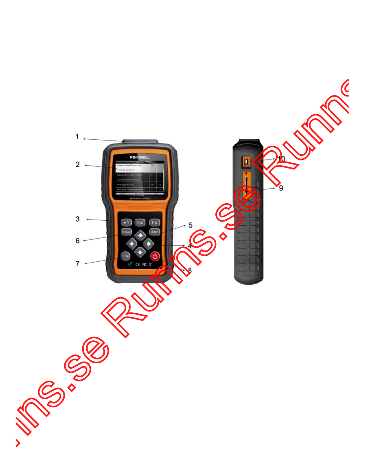
Figure 2-1 Front View
1 Diagnostic Port - provides connection between the EPB service tool and vehicle.
2
LCD Display - shows menus, test results and operation tips.
3
Function Keys / Shortcut keys - three keys that correspond with “buttons” on some screens
for executing special commands or provide quick access to most frequently used applications
or functions.
4
Direction Keys - sel ec t an opt i on or scroll through a screen of data or text.
5
BACK Key - exits a screen and generally returns to previous screen.
6
ENTER Key - executes a selected option and generally goes to the next screen.
7
HELP Key - displays helpful information.
8
Po wer Swit ch - turns on/off the EPB service tool and press and hold for 5 seconds for
emergency reboots.
9
SD Card Port - holds the SD memory card for data backup and software update.
10
USB Port - provides a USB connection between the EPB service tool and PC or laptop.
Page 9

9
NT415 EPB Service Tool Manual_English_V1.01
IMPORTANT
Do not use solvents such as alcohol to clean keypad or display. Use a mild nonabrasive detergent
and a soft cotton cloth.
2.2 Accessory Descriptions
This section lists the accessories that go with the EPB service tool. If you find any of the following
items missing from your package, contact your local dealer for assistance.
1
User’s Guide - provides operation instructions for the usage of the EPB service tool.
2
USB Cable - provides connection between the EPB service tool an d a computer to upgrade the
tool.
3
Memory Card - contains the EPB service tool’s operating software and applications.
IMPORTANT
Do not remove the memory card unless performing updates to the card.
4 Diagnostic Cable - provides connecti on between the EPB service tool and vehicle.
5
Nylon Carry Pouch - stores the EPB service tool and its accessories.
2.3 Technical Specifications
Display: Backlit, 480*272 TFT color display
Working Temperature: 0 to 60 ℃ (32 to 140℉)
St or age Temperature: -20 to 70℃ (-4 to 158℉)
Power Supply: 8-18V vehicle power, 12V AC/DC power, 3.3V USB power
Dimensions (L*W*H): 200*130*40mm
Gross Weight: 1.2Kg
Protocols: SAE J1850 (VPW and PWM), ISO 9141-2, ISO 14230-2 (KWP 2000), ISO 15765-4
(CAN)
3 Getting Started
This section describes how to provide power to the EPB service tool, provides bri ef i ntroducti ons
of applications loaded on the EPB service tool and display screen layout and illustrates how to
input text and numbers with the EPB serv ice tool.
3.1 Providing Power to EPB Service Tool
Before using the EPB service tool, make sure to provide power to the EPB service tool.
The unit operates on any of the following sources:
● 12-volt vehicle power
● USB connection to personal computer
3.1.1 Connecting to Vehicle Power
The EPB service tool normally powers on whenever it is connected to the data link connector
(DLC).
To connect to vehicle power:
1. Locate the data link connector (DLC). The DLC is generally located under the dash on the
driver side of the vehicle.
2. Attached the diagnostic cable to the EPB service tool and tighten the captive screws to ensure
good connection.
Page 10
10
NT415 EPB Service Tool Manual_English_V1.01
3. Connect a correct adapter to the data cable according to the vehicle being serviced and plug it
into the vehicle DLC.
4. Switch the ignition key to the ON position.
5. The EPB service tool automatically boots up.
IMPORTANT
Never try to provide power for the EPB service tool from USB connecti on when the EPB s e r vice
tool is communicating with a vehicle.
3.1.2 Connecting to Personal Computer with
USB Cable
The EPB service tool also receives power through the USB port when it is connected to a PC for
updating software and transferring saved files.
To connect to PC:
1. Insert the small end of the USB cable to the USB port at the right side of the EPB service tool
and the large end to a computer.
2. Press the power switch of the EPB service tool to power it on.
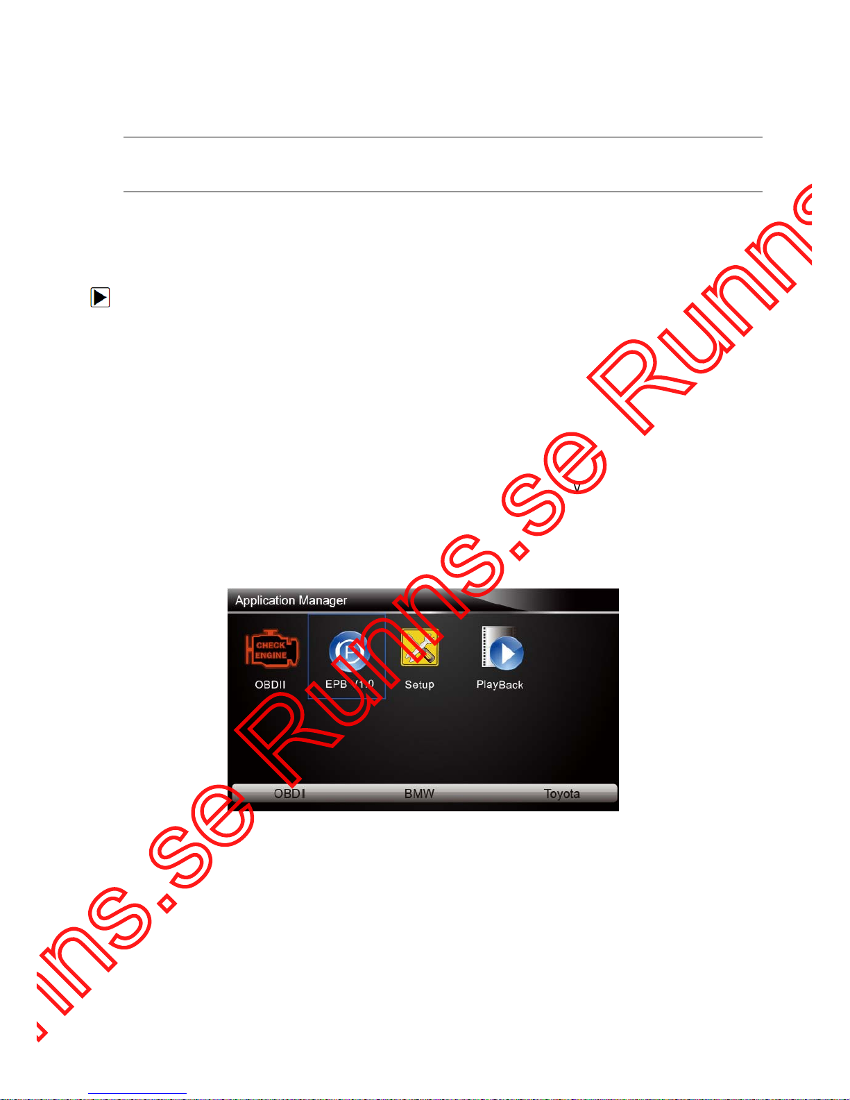
3.2 Application Overview
When the EPB service tool boots up, the home screen opens . This screen shows all applications
loaded on the unit.
Following applications are preloaded into the EPB service tool:
● OBDII/EOBD – leads to OBDII screens for all 9 generic OBD system tests.
● EPB – leads to screens for diagnostic trouble code information, live datastream, ECU
information, special functions of electric parking brake systems on 13 vehicle makes sold
worldwide.
● Setup – leads to screens for adjusting default settings to meet your own preference and view
information about the EPB service tool.
● Playback – leads to screens for access saved data files.
Figure 3-1 Sample Home S creen
3.3 Input Dialog Box
This section illustrates how to use the tool to input letters and numbers, such as VIN number,
channel number, test values and DTC number. Typically, you may be required to input letters or
numbers when you are doing any of the following operations.
● VIN entry
● input channel number
● set adaptation value
● look up DTCs
Page 11
11
NT415 EPB Service Tool Manual_English_V1.01
The tool provides 4 different types of keyboard to meet your specific needs. Depending on the
needs of text entry, it automatically shows the most suitable keypad.
● classic QWERTY keyboad for input of texts that contain both letters and numbers
● numeric keyboard for input of numbers
● alphabet keyboard for i nput of letters
● hexadecimal keyboard for special functions.
To input text with the EPB service tool:
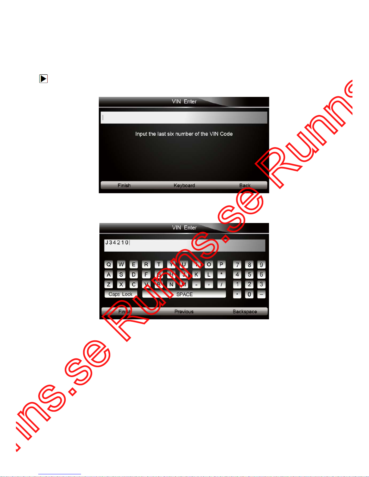
1. When you are requested to input text, press the function key Keyboard, and the keyboard
displays.
Figure 3-2 Sample Input Text Screen
2. Scroll with the arrow keys to highlight your desired letter or number and press the ENTER key
to confirm.
Figure 3-3 Sample Numeric Keyboard Screen
3. To delete a letter or number, use the function key Previous to move the cursor to it and then
press the
Backspace button.
4. When finished the entry, press Finish key to continue.
4 Diagnostic Operations
This section illustrates how to use the EPB service tool to read and clear diagnostic trouble codes,
and view “live” data readings and ECU information on Electronic Parking Brake systems of 13
vehicles and also save “recordings” of the data readings.
4.1 Vehicle Identification
The vehicle identification information presented is provided by the ECM of the vehicle being
tested. Therefore, certain attributes of the test vehicle must be entered into the tool to ensure the
Page 12
12
NT415 EPB Service Tool Manual_English_V1.01
data displays correctly. The vehicle identification sequence is menu driven, you simply follow the
screen prompts and make a series of choices. Each selection you make advances you to the next
screen. Exact procedures may vary somewhat by vehicle.
It typically identifies a vehicle by the following methods.
● Manual vehicle selection
● Manual VIN entry
NOTE
Not all identification procedure listed below is applicable to all vehicles. A vail abl e opti ons may
vary by vehicle manufacturer.
4.1.1 Manual Vehicle Selection
To identify a vehicle by manual vehicle selection:
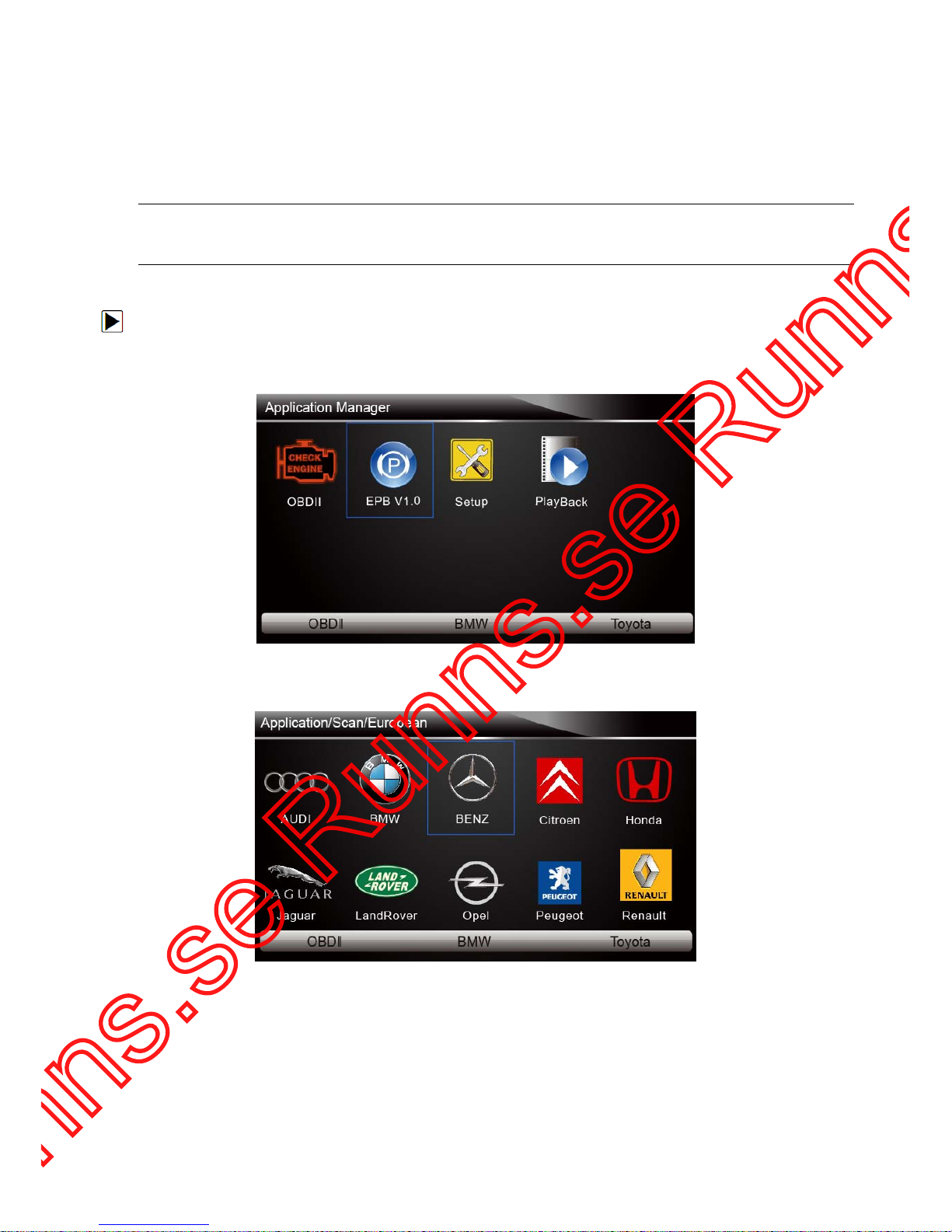
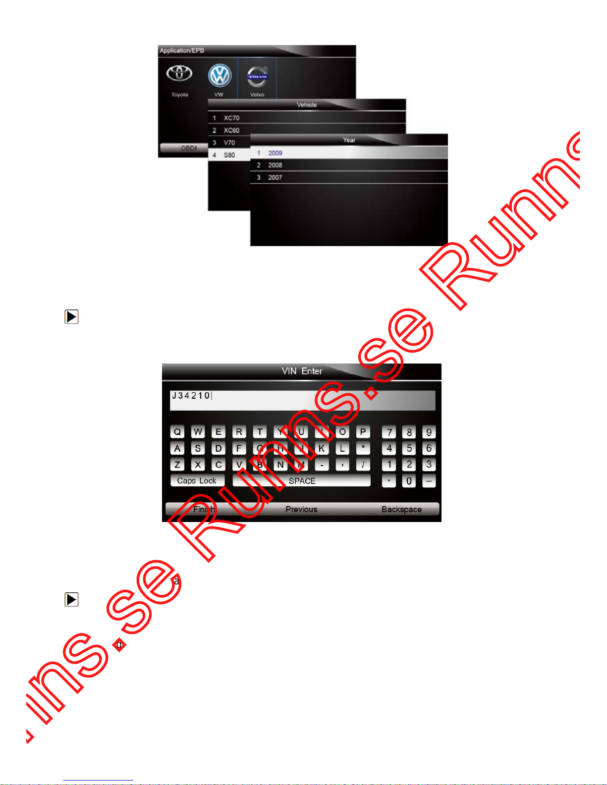
1. Scroll with the arrow keys to highlight EPB from the Application menu and pres s the ENTER
key to start . If yo u have the application assigned to one of the function keys at the bottom of the
screen, you can alternatively press the function key to start the application.
Figure 4-1 Sample Application Menu
2. A screen with vehicle manufacturer displays. Select the vehicle manufacturer being tested.
Figure 4-2 Sample Vehicle Manufacturer Selection Screen
3. On each screen that appears, select the correct option and then press the ENTER key. Do this
until the complete vehicle information is entered and the diagnostic menu displays.
Page 13
13
NT415 EPB Service Tool Manual_English_V1.01
Figure 4-3 Sample Vehicle Selection Screen
4.1.2 Manual VIN Entry
Manual VIN Entry identifies a vehicle by manually inputting a 17-digit VIN code.
To identify a vehicle by manual VIN entry:
1. Refer to Step 1-2 of 4.1.1 manual vehicle selection.
2. A virtual keyboard opens for VIN entry. Input a valid VIN code as required on screen and use
the function key
Finish t o confirm. The tool starts to identify the vehicle.
Figure 4-4 Sample Manual VIN Entry with Keyboard
4.2 Diagnostic Function Selection
This section illustrates how to work on the electronic parking brake systems.
To perform diagnosis:
1. Turn the ignition off.
2. Release the park brake and make sure the car is properly blocked.
3. Locate the vehicle’16-pin Data Link Connector (DLC)
4. Plug into the diagnostic cable to the vehicle’s DLC.
5. Turn the ignition on.
6. Scroll with the arrow keys to highlight EPB from Home screen and press the ENTER key.
7. After you have completed the identification of vehicle and the EPB service tool establishes
communication with the vehicle, the Diagnostic Menu displays.
The menu options may include:
Page 14
14
NT415 EPB Service Tool Manual_English_V1.01
● Read Codes
● Erase Codes
● Live Data
● ECU Information
● Special Function
NOTE
Not all function options listed above are applicable to all vehicles. Available options may vary by
the year, model, and make of the test vehicle. A “The selected mode is not supported!” message
displays if the option is not applicable to the vehicle under test.
4.2.1 Read Codes
Read Codes menu lets you read trouble codes found in the control unit.
To read codes from a vehicle:
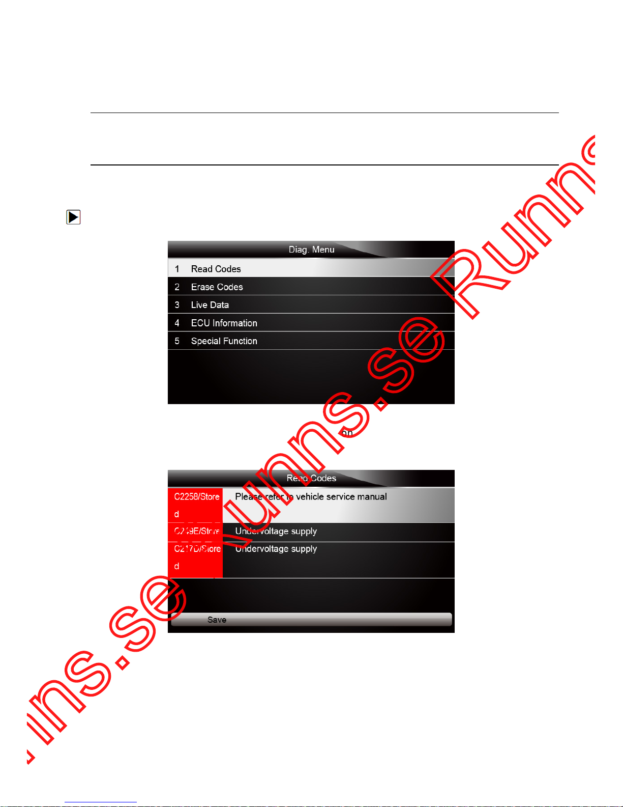
1. Scroll with the arrow keys to highlight Read Codes from Diag. Menu and press the ENTER key.
Figure 4-5 Sample Function Menu Screen
2. A code list including code number and its description displays. Use the up and down arrow keys
to scroll through data to select lines, and left and right arrow keys to scroll back and forth
through different screens of data.
Figure 4-6 Sample Code Screen
3. Press function key
Save to store DTC information. Or use the BACK key to exit.
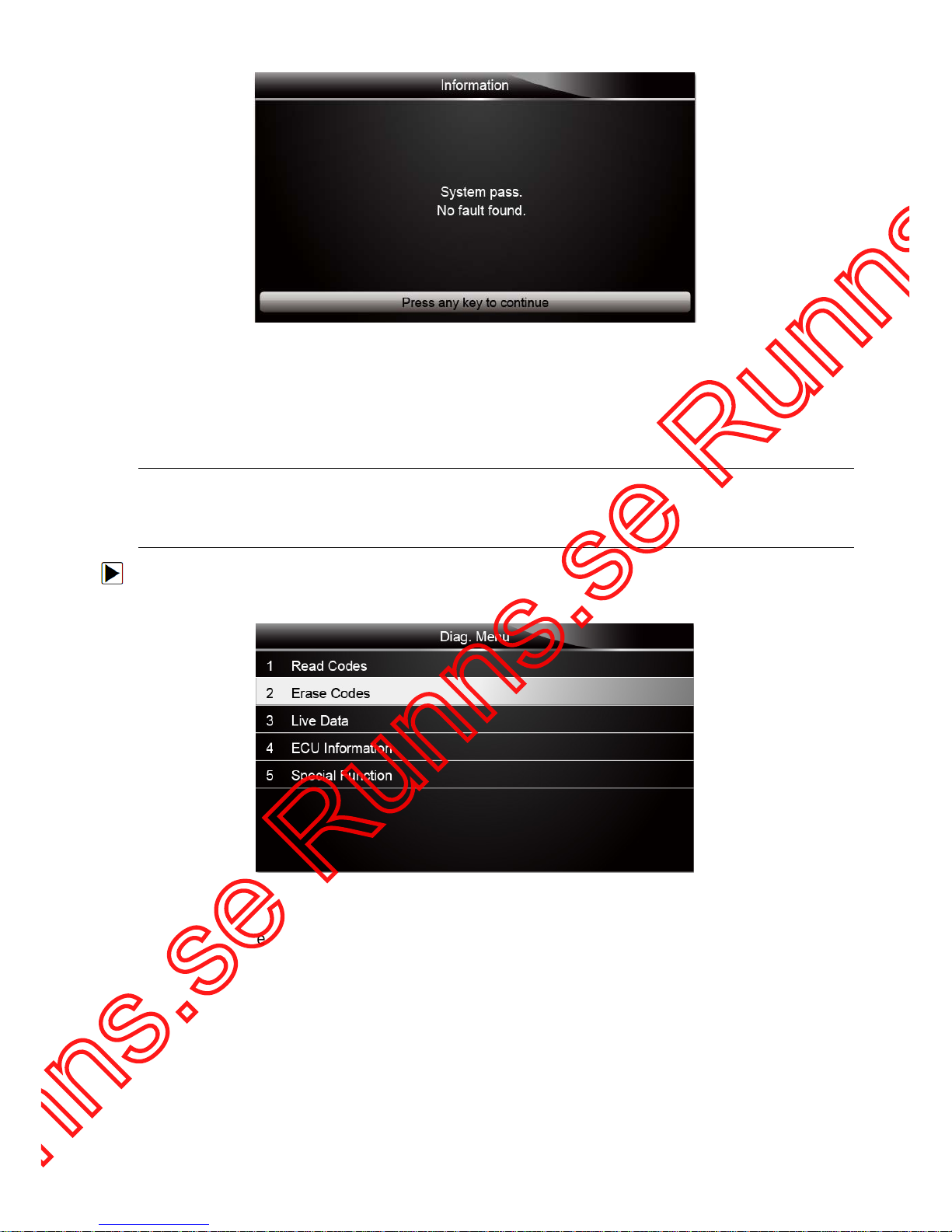
3. If there is no trouble code, the following screen displays. Press any key to return to the function
menu.
Page 15
15
NT415 EPB Service Tool Manual_English_V1.01
Figure 4-7 Sample No Fault Screen
4.2.2 Erase Codes
Erase Codes menu lets you to clear all current and stored DTCs from the control module. Also it
erases all temporary ECU information, so make sure that the selected system are completely
checked and serviced by technicians and no vital information will be lost before clearing codes.
NOTE
● To clear codes, make sure that the ignition key is switched to ON with the engine off.
● Erase Codes does not fix the problem that caused the fault! DTCs should only be erased after
correcting the condition(s) that caused them.
To clear codes:
1. Scroll with the arrow keys to highlight Erase Codes from Diag. Menu and press the ENTER
key.
Figure 4-8 Sample Function Menu Screen
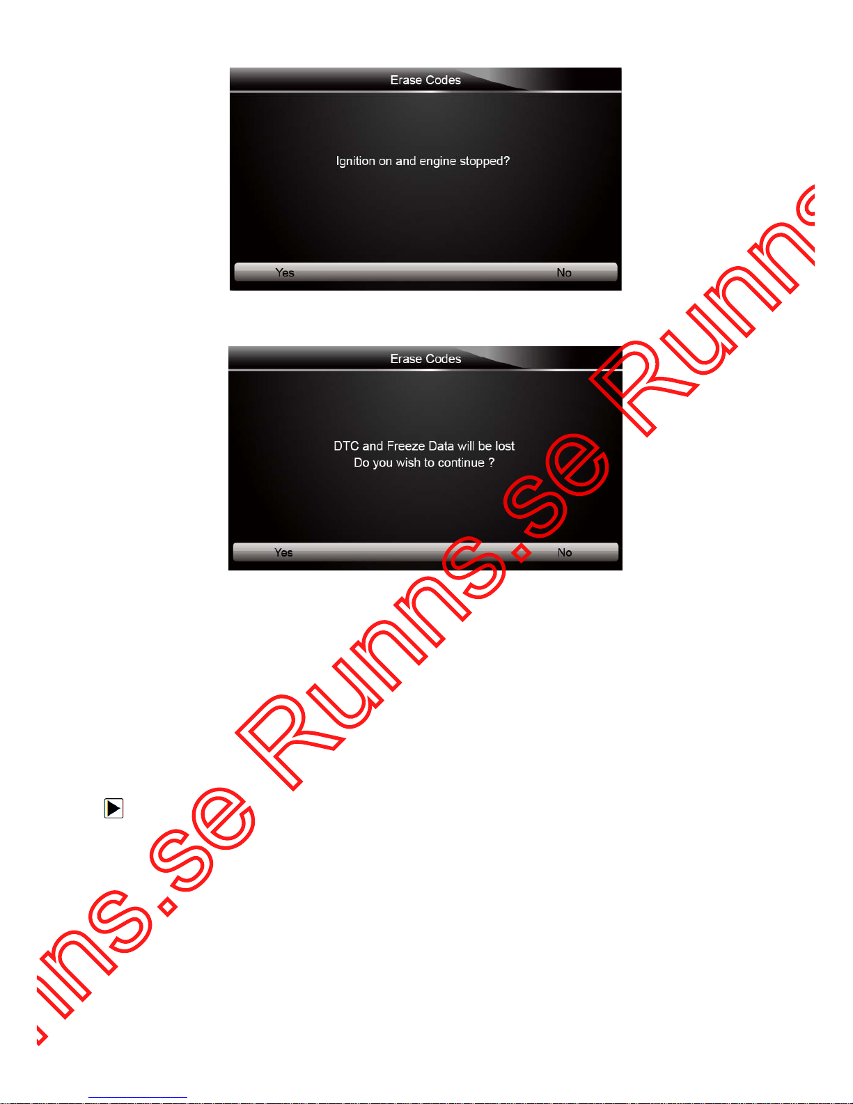
2. Follow the on-screen instructions and answer questions about the vehicle being tested to enter
into next screen.
Page 16
16
NT415 EPB Service Tool Manual_English_V1.01
Figure 4-9 Sample Erase Codes Screen 1
3. Press the function key
Yes to complete the procedure.
Figure 4-10 Sample Erase Codes Screen 2
3. Check the codes again. If any codes remain, repeat the Erase Codes steps.
4.2.3 Live Data
Live Data menu lets you view and record real time PID data from EPB system.
Menu options typically include:
● All Data List
● Custom Data L ist
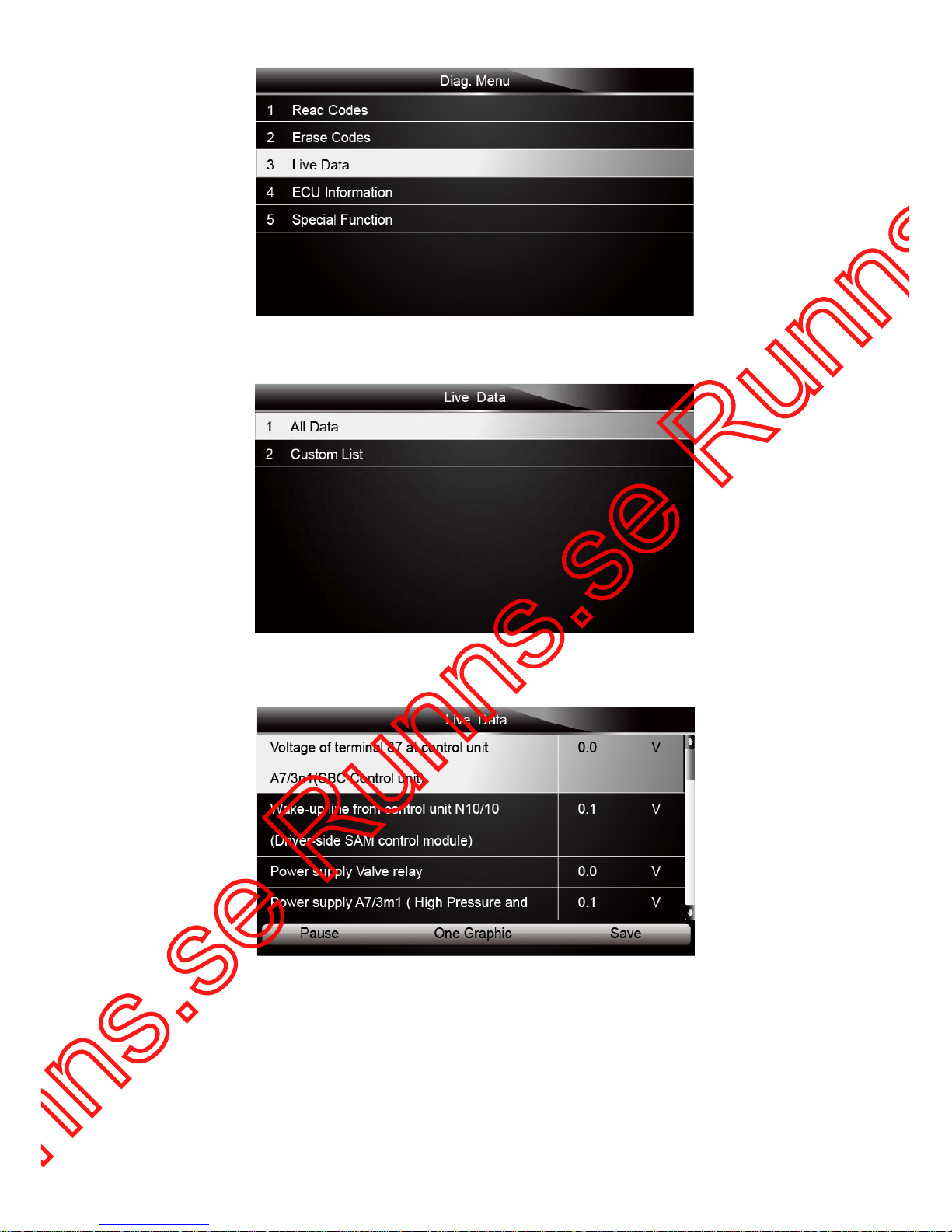
4.2.3.1 A ll Data List
ALL Data List menu lets you view all live PID data from EPB system.
To view all live PID data
1. Scroll with the arrow keys to highlight Live Data from the menu.
Page 17
17
NT415 EPB Service Tool Manual_English_V1.01
Figure 4-11 Sample Diag. Menu Screen
2. Press the ENTER key to display the live data menu.
Figure 4-12 Sample Live Data Selection Screen
3. Select the All Data from the menu and press the ENTER key to display the datastream screen.
Figure 4-13 Sample All Data Screen
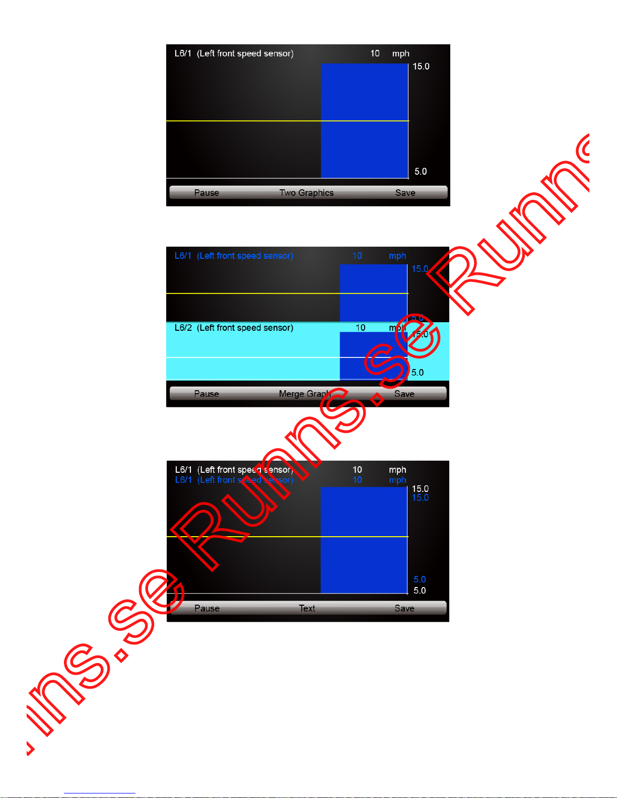
4. Scroll with the up and down arrow keys to highlight a line, if the One Graphic on the bottom is
highlighted, it indicates the graphing is available for the selected line. Press t he function key
One G rap hi c to display the PID graph.
Page 18
18
NT415 EPB Service Tool Manual_English_V1.01
Figure 4-14 Sample PID graph Screen
5. Press the function key Two Graphics to display two PID graphs in one screen.
Figure 4-15 Sample Two PID Graph Screen
6. Press the function key Merge Graph to display two PID plots in one coordinate for easy and
intuitive diagnosis.
Figure 4-16 Sample Merged PID Plots Screen
7. To record the data to memory of the EPB service tool, use the function key SAVE, and press
Stop Saving to stop recording at any time.
8. Press Text to return to text viewing of PID data.
9. Select Pause to suspend collecting data from the EPB service tool and use the Continue key
to resume collecting data.
10.Press the Back key to return to the previous menu.
Page 19
19
NT415 EPB Service Tool Manual_English_V1.01
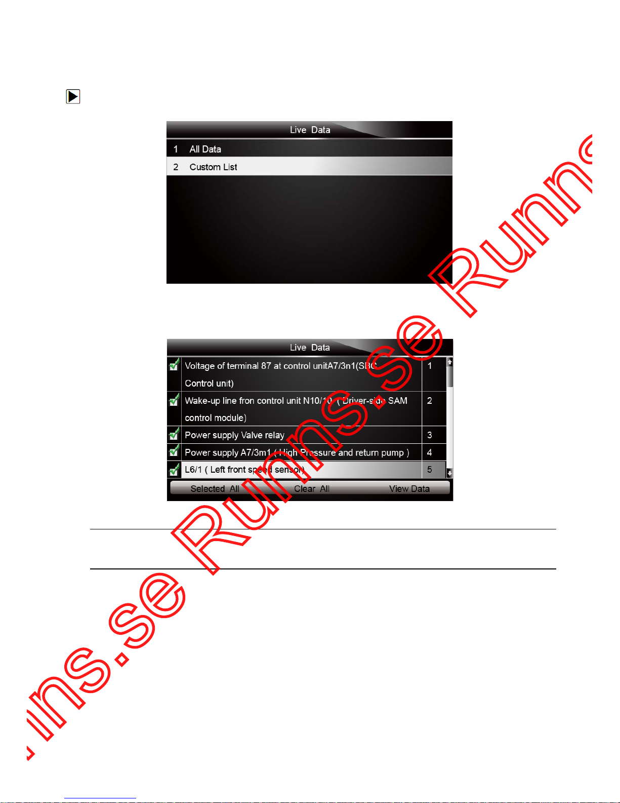
4.2.3.2 Custom Data List
Custom Data List menu lets you to minimize the number of PIDs on the data list and focus on any
suspicio us or sy mptom-specific data parameters.
To create a custom data list:
1. Select Custom List from the menu and press the ENTER key.
Figure 4-17 Sample Live Data Screen
2. The custom datastream selection screen displays. Scroll with the up and down arrow keys to
highlight a line, press the
ENTER key and then repeat the action to make more selections.
Figure 4-18 Sample Custom List Selection Screen
NOTE
To deselect an item, select it again and then press the ENTER key. Alternatively, use the function
keys
SELECT ALL and CLEAR ALL to select or deselect all items at once.
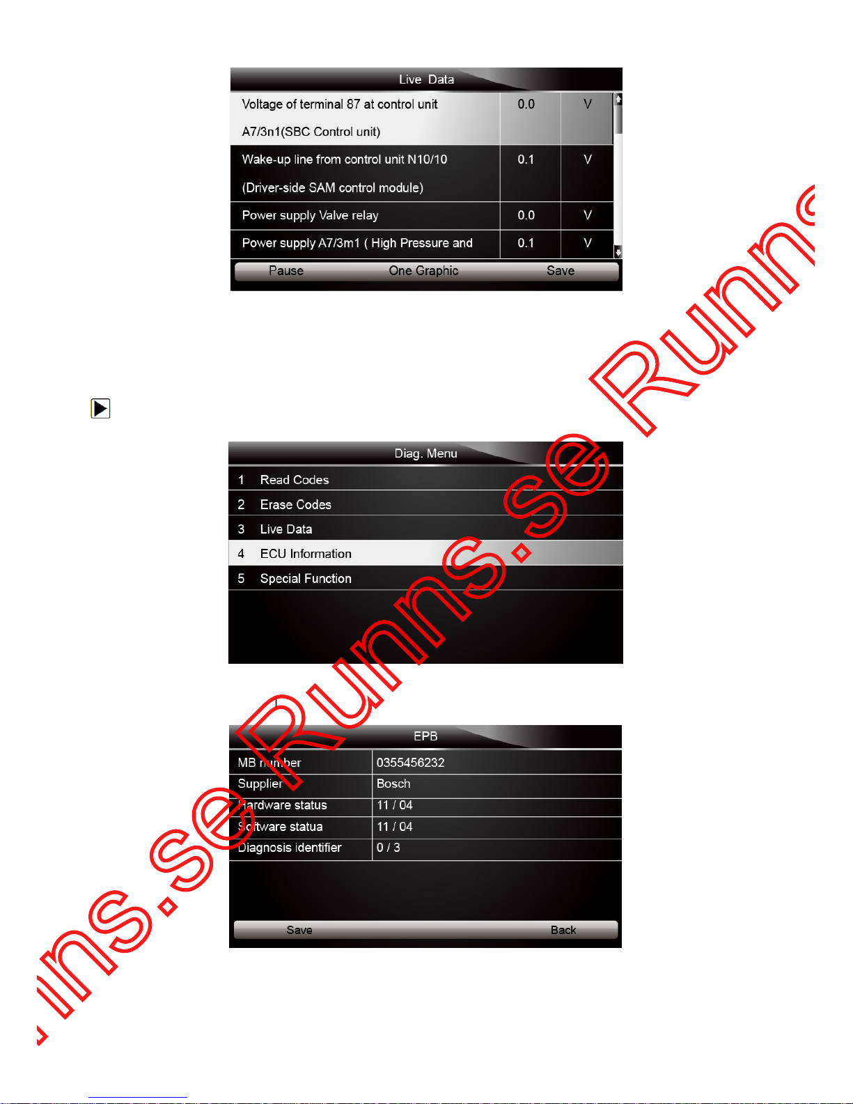
3. When finished selection, use the function key VIEW DATA to display s el ect ed items.
Page 20
20
NT415 EPB Service Tool Manual_English_V1.01
Figure 4-19 Sample Datastream Screen
4.2.4 ECU Information
ECU Information screen displays the identification dat a of the control module under test, s uch as
the control module identification string and the control module coding.
To read ECU information:
1. Select ECU Information from Diag. menu and press the ENTER key.
Figure 4-20 Sample Function Menu Screen
2. A screen with detailed information of the selected control module displays.
Figure 4-21 Sample ECU Information Screen
3. Press function key Save to store ECU information. Or use the BACK key to exit.
Page 21

21
NT415 EPB Service Tool Manual_English_V1.01
4.2.5 Special Functions
Special Functions let you perform bi-directional tests on electronic parking brake systems of
multiple vehicle brands. The tests let you to deactivate and re-activate brake control system, set
new brake pad thickness after AUDI A8 service, bleed the brake systems and more.
Some tests display a command to the operator. For example, if “Pressing Brake Pedal” displays,
the operator has to press and hold the brake pedal and then continue. Actual tests vary by vehicle
manufacturer, year, make.
Typical special test options include:
● Deactivate/Activate SBC/EPB systems – allows to deactivate brakes for further service or
maintenance work on brake systems or activate brakes when service or maintenance work
on brake systems are completed.
● Adaptation on Audi A8 – allows to set new pad thickness of rear brakes calipers after
changing brake discs & pads on Audi A8 models.
● Replace hydraulic brake systems fluid/bleed brake system on Mercedes SBC vehicles –
allows to change brake fluid/bleed brake system.
● Perform service reset and ser vice position on BMW EPB vehicles – allows to do the CBS
reset and CBS correction for front brake and rear brake.
● Perform activation/service work on Volvo PBM vehicles – allows to perform installation
check, applying parking brake, releasing parking brake, acti vat i ng service mode and exiting
service mode.
● Reset m emory on Toyota EPB vehi cles – allows to clear the learned memory of the EPB
ECU.
● Per fo rm brake cable replacement and electric parki ng br ake replacem ent – allows to fit
in or remove the brake cable s afely, adjust brake cable’s tension and calibrate the electric
parking brake replacement.
● Save and write clutch pedal programming on Renault EPB vehicles – allows to save
clutch pedal programming on Renault vehicles fitted with manual gearbox. After this
command is activated, the tool allows to "flash" the electric parking brake unit with the saved
clutch data.
● Perform control function and reset function on Opel EPB vehicles – allows to
apply/release park brake cable service, provide park brake cable service replacement
procedures and calibrate the parking brake systems after brake service.
● Sensor calibration on Honda EPB vehicles – allows to program the current output value of
each sensor into the electric parking brake unit.
● Provides parking brake unjam procedure and perform longitudinal accelerometer
calibration on Land Rover E PB vehicles – allows to drive the electronic park brake so it is
unjamed in the releasing direction and then drive it into mounting position or the latching
position; also allows to perform longitudinal accelerom eter cali brat i on.
● EPB systems must be deactivated before carrying out any maintenance/service work on the
brakes such as changing of pads, discs and calipers.
● Use proper tools to avoid the risk of body injuries of mechanics and technicians and damage
to the brake system.
● Make sure the vehicle is properly blocked after deactivation of the systems.
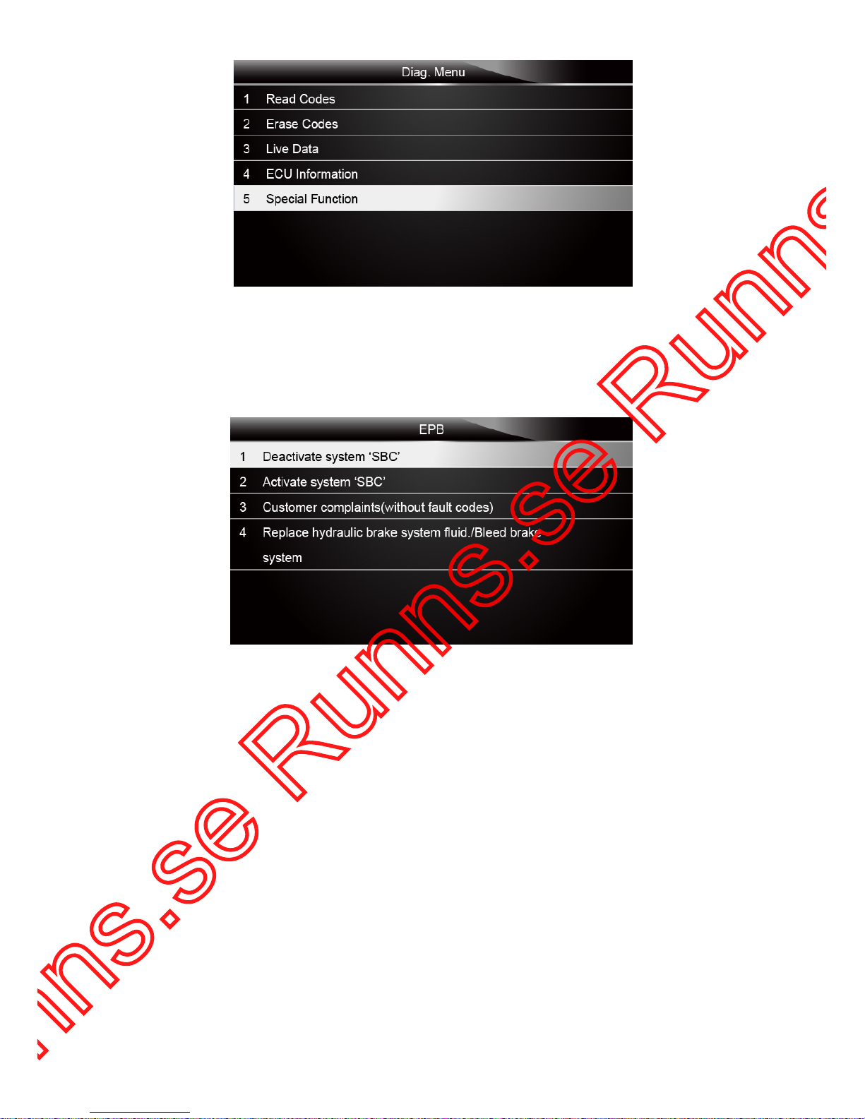
To perform special tests on a vehicle:
1. Scroll with the arrow keys to highlight the Special Function from the Diag. Menu and press the
ENTER key.
Page 22
22
NT415 EPB Service Tool Manual_English_V1.01
Figure 4-22 Sample Function Menu Screen
2. A group selection screen, test selection screen, several step-by-step instruction screens may
appear. Select the special function you want to perform from the menu and press the
ENTER
key. Read and follow all on-screen instructions carefully. If necessary, use the function keys to
perform commands or answer any questions. If more than 3 function keys displays, use the left
and right arrow keys to select a command and press the
ENTER key to confirm.
Figure 4-23 Sample Special function Screen
3. When completed, press the BACK key to return to previous screens.
5 OBDII/EOBD Operations
OBD-II/EOBD menu lets you access all OBD service modes. According to ISO 9141-2, ISO
14230-4, and SAE J1850 standards, the OBD application is divided into several sub programs,
called ‘Service $xx’. Below is a list of OBD diagnostic services:
● Service $01 - request current powertrain diagnostic data
● Service $02 - request powertrain freeze frame data
● Service $03 - request emission-related diagnostic trouble codes
● Service $04 - clear/reset emission-related diagnos t ic inf orm ation
● Service $05 - request oxygen sensor monitoring test results
● Service $06 - request on-board monitoring test results for specific monitored systems
● Service $07 - request emission-related diagnostic trouble codes detected duri ng current or
last completed driving cycle
● Service $08 - request control of on-board system, test or component
● Service $09 - request Vehicle Information
Page 23
23
NT415 EPB Service Tool Manual_English_V1.01
When OBDII/EOBD application is selected from Home screen, the EPB servic e tool starts to
detect the communication protocol automatically. Once the connection has established, a menu
that lists all of the tests available on the identified vehicle displays. Menu options typically include:
● System Sta tu s
● Read Codes
● Freeze Frame Data
● Erase Codes
● Live Data
● I/M Readiness
● O2 Sensor Test
● On-board Monitor Test
● Component Test
● Vehicle Information
● Modules Present
● Code Lookup
NOTE
Not all function options listed above are applicable to all vehicles. Available options may vary by
the year, model, and make of the test vehicle. A “The selected mode is not supported!” message
displays if the option is not applicable to the vehicle under test.
5.1 System Status
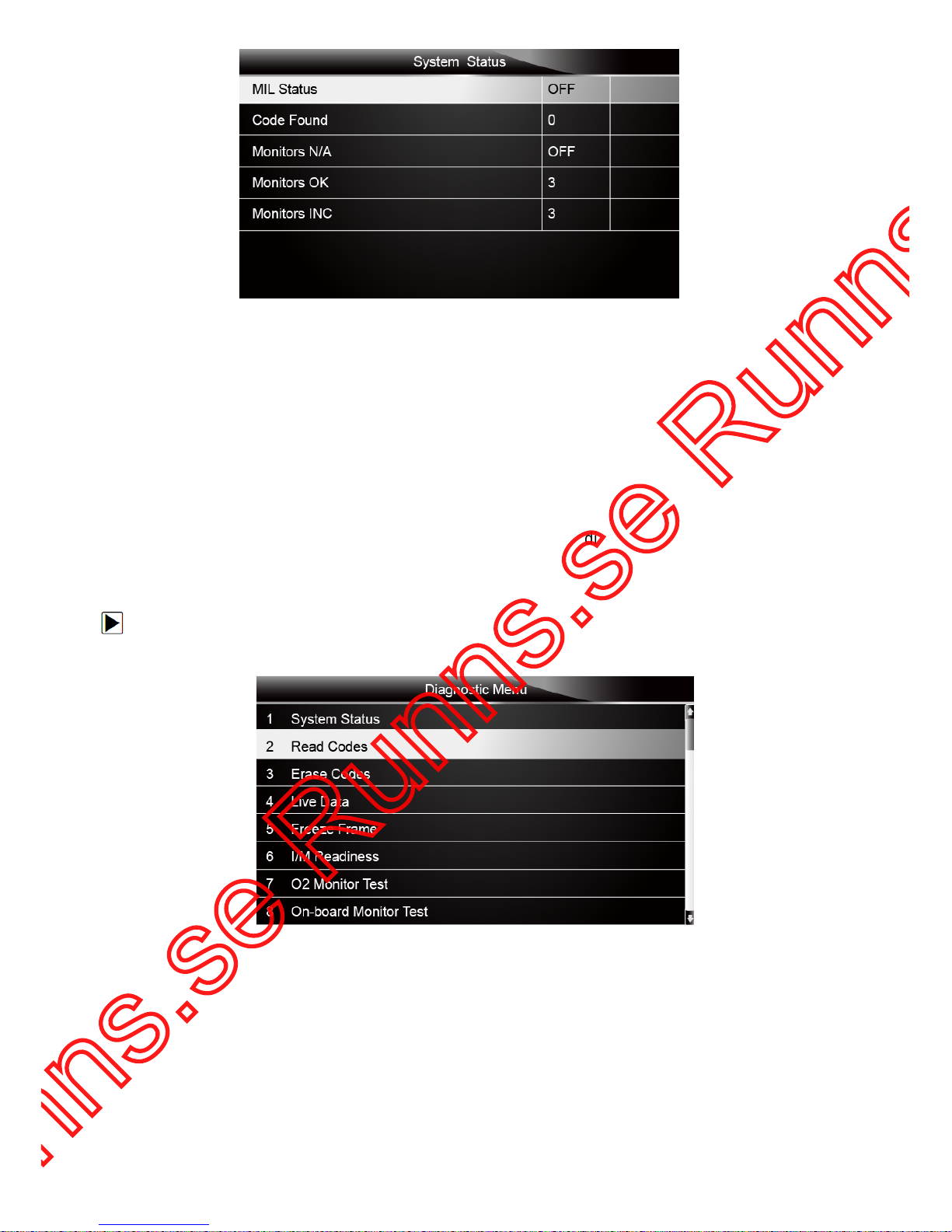
System Status option open a screen with a summary of system status of the vehicle under test.
To view summary system status of a vehic l e:
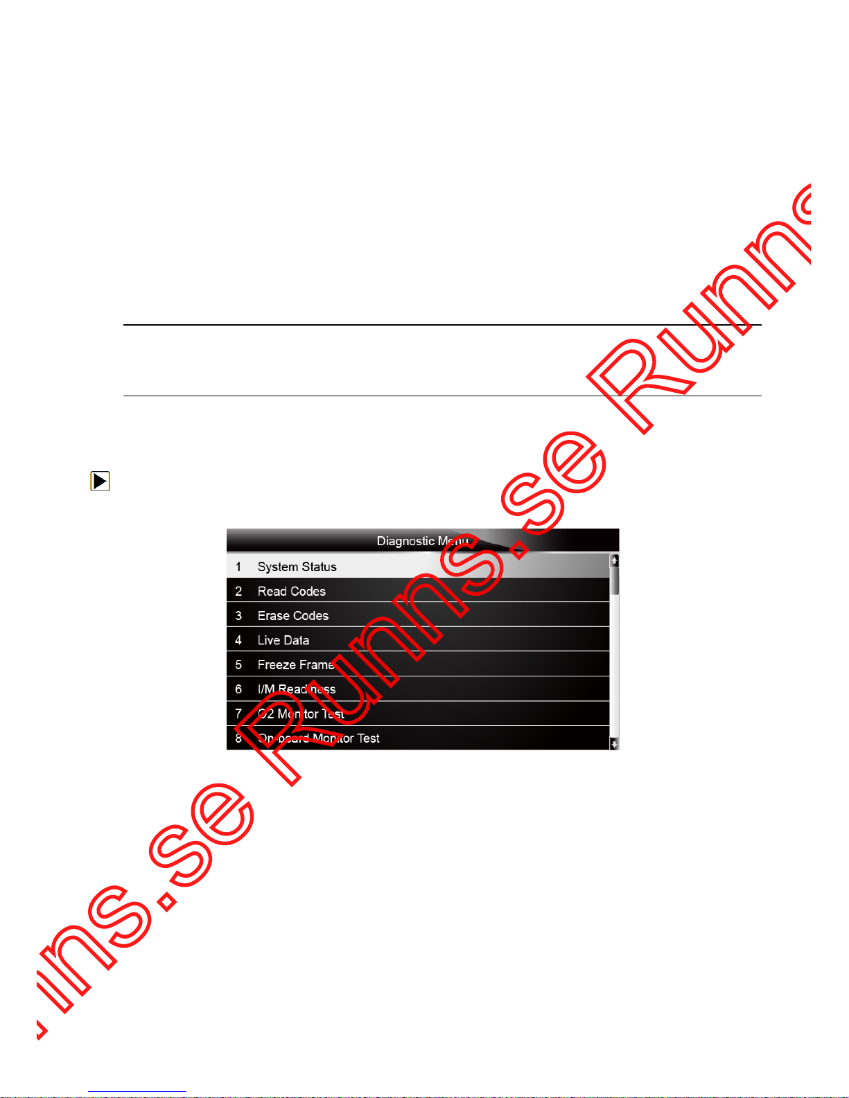
1. Scroll with the arrow keys to highlight System Status from Diagnostic Menu and press the
ENTER key.
Figure 5-1 Sample Diagnostic Menu Screen
2. A screen with detailed information displays.
Page 24
24
NT415 EPB Service Tool Manual_English_V1.01
Figure 5-2 Sample System Status Screen
5.2 Read Codes
Read Codes menu lets you read both stored codes and pending codes found in the control unit.
Typical menu options include:
● Stored Codes
● Pending Codes
Diagnostic trouble codes stored in a control module are used to help identify the cause of a
trouble or troubles with a vehicle. These codes have occurred a specific number of times and
indicate a problem that requires repair.
Pending codes are also referred to as maturing codes that indicate intermittent faults. If the fault
does not occur within a certain number of drive cycles (depending on vehicle), the code clears
from memory. If a fault occurs a specific number of times, the code matures into a DTC and the
MIL illuminates or blinks.
To read codes/pending codes from a vehicle:
1. Scroll with the arrow keys to highlight Read Codes from Diagnostic Menu and press the
ENTER key.
Figure 5-3 Sample Diagnostic Menu Screen
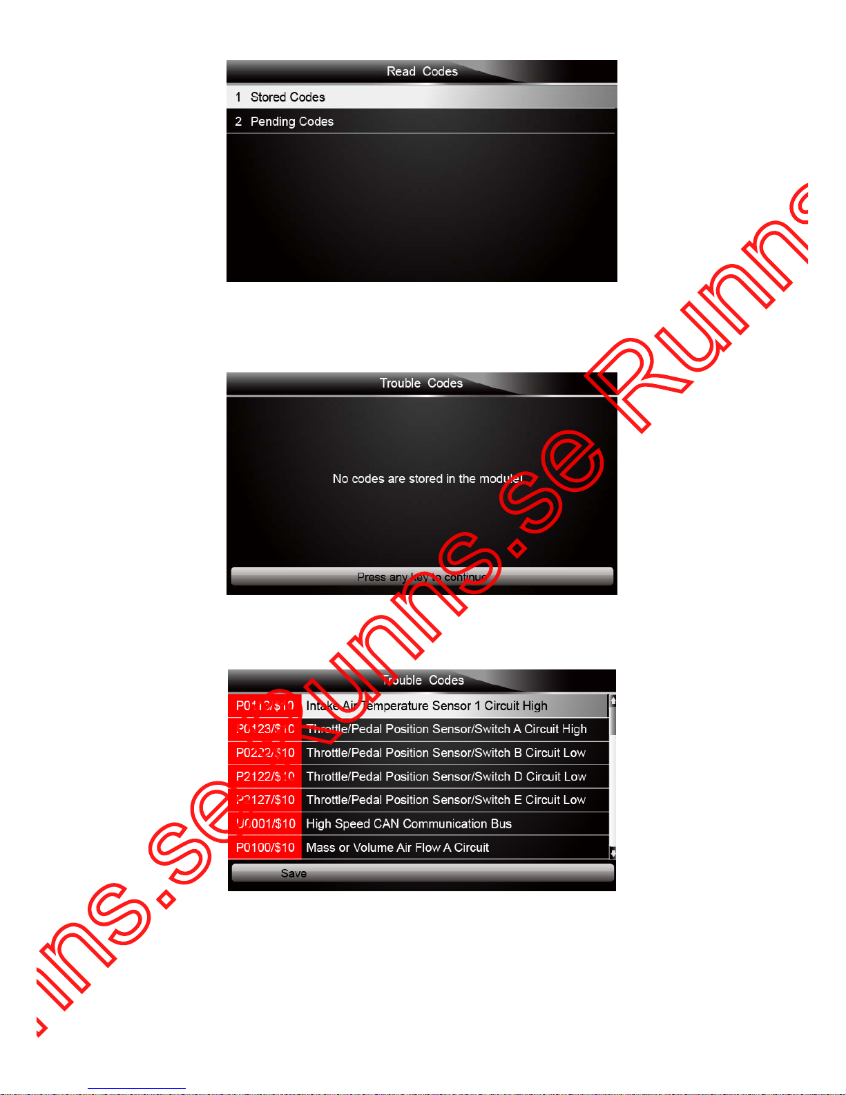
2. Select Stored Codes/Pending Codes and press the ENTER key to confirm. A code list
including code number and its description displays.
Page 25
25
NT415 EPB Service Tool Manual_English_V1.01
Figure 5-4 Sample Read Codes Screen
If no DTCs are present the message “No (Pending) Codes Found!” is displayed. If any
manufacturer specific or enhanced codes detected, select vehicl e a make before viewing DTC
information.
Figure 5-5 Sample No Codes Screen
3. Use the up and down arrow keys to scroll through data to select lines, and left and right arrow
keys to scroll back and forth through different screens of data.
Figure 5-6 Sample Code Screen
4. Press function key Save to store DTC information. Or use the BACK key to exit.
 Loading...