

foxunhd FX-EX37 Operating Instructions Manual

Operating Instructions
FX-EX37
4K HDMI+USB KVM Extender over IP / Fiber
Dear Customer
Thank you for purchasing this product. For optimum performance and safety, please read these
instructions carefully before connecting, operating or adjusting this product. Please keep this manual for
future reference.
ABLE OF CONTENTS
Feature
Specifications
Package Contents
Panel Descriptions
Connecting and Operating
Typical Application
Product Service
Warranty
www.foxunhd.com

Operating Instructions
4k UHD HDMI over IP extension
USB 2.0 over IP extension
RS232 bi-directional extension and RS232 control
4 bits Switch for 16 stream channel selection
Support Dolby True HD, DTS-HD Master Audio
Support two way wide Band IR extension(38khz-56khz)
Transmit over single Cat5e/6 cable up to 120m
Transmitter over Fiber Optical cable up to 60km(Single Mode)
Networking environment under Giga Enthernet switch and Cat5e cable
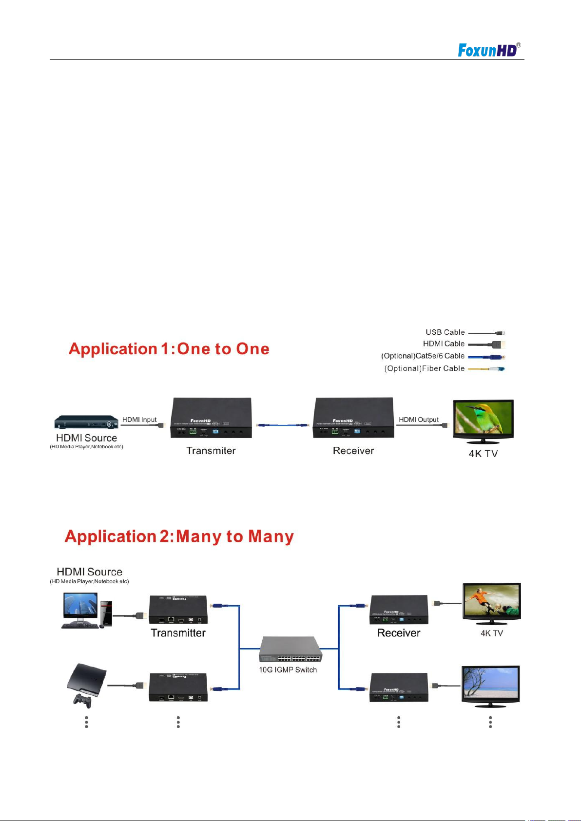
Point to Point extension,Unicast, Multicast and Video wall system(max 8x16)
Output video rotation
Output video video partial enlargement
HDCP1.4 compliant
Protocol
TCP, UDP, RTSP, RTP, DHCP, IGMP, Multicast, IPV4
Support Video format
4K@30HZ, 1080P/1080i/720P/576P/576i/480P/480i
Support Audio format
Stereo 192Kbps
HDCP
Compliant
IR Frequency
38 -56 KHZ
RS232 Baud rate
Default 115200bps, total 8 kinds optional
IP setting &Group ID setting
Default IP
Automatic allocation
Group ID
Group 00 ~ group 16
Request for Switch/Router
Support IGMP, support DHCP
Connectors on Transmitter
Input
1xHDMI Female port, 1xUSB B type
Output
1x RJ45 output, 1x Fiber output
RS232
Phoenix RS232 port
IR
1x IR TX port; 1x IR RX port
Support 38K-56KHz
Connectors on Receiver
Input
1xRJ45 input, 1x Fiber input
Output
1x HDMI Female port, 2x USB A type
Feature
NOTICE
Our company reserve the right to make changes in the hardware, packaging and any accompanying
documentation without prior written notice.
SPECIFICATIONS
Performance
www.foxunhd.com

Operating Instructions
RS232
Phoenix RS232 port
IR
1x IR TX port; 1x IR RX port
Support 38K-56KHz
Environmental & Power Requirements
Operating temperature
-5 to +65℃(+23 to +149℉)
Operating Humidity Range
5 to 90%RH (No Condensation)
Power supply
DC 5V
Power consumption
Max 3 watt
Physical
Dimension
TX: 160x103.2x30mm ; RX: 160x103.2x30mm
Net Weight
TX: 472.8G ; RX:472.3G
1) Main Unit. HDMI Extender( transmitter & receiver)
2) Power adapter DC5V 2A x2PCS
3) 2xIR TX cable, 2xIR RX cable
4) 2xPhoenix plugs for RS232 cable termination
5) 4xscrews
6) Rear bracket x2
7) Operating Instruction
Note1: Specifications are subject to change without notice. Mass and
dimensions are approximate.
Note2: when transmit over Fiber. 4kx2k require 3.125g module.
PACKING CONTENTS
Notes: Please confirm if the product and the accessories and all in duded, if not please contact with
the dealers.
PANEL DESCRIPTION
www.foxunhd.com
Operating Instructions
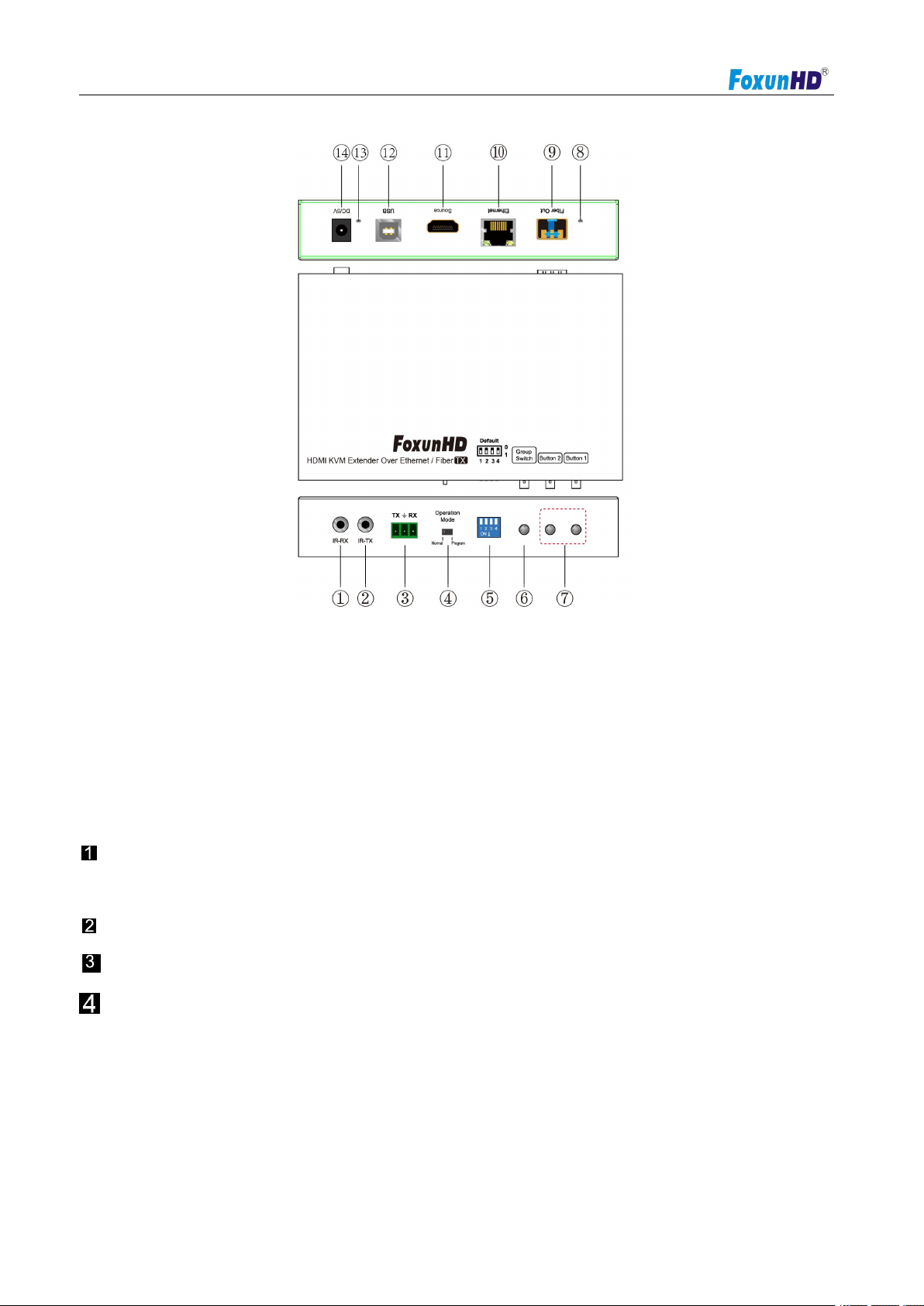
1) IR-RX port 2) IR-TX port
3) RS232 port 4) Normal: For serial over IP;
5) 4 bit Dip switch 6) Group Switch③
7) Button 1&2 ④ 8) Indicator of status ②
9) Fiber out 10) Ethernet port
11) HDMI input 12)USB
13)Power input indicator① 14)Power input port
A. Green LED: Link LED, when the connection has established over Cat5e/6 cable or Fiber
cable, the Green LED will illuminate.
B. Yellow LED: When the yellow LED is blinking, it indicates the connection has been established over Cat5e/6 cab
le.
When the green LED illuminates, it indicates the connection has been established between
transmitter and receiver over fiber cable.
After select the DIP switch, press “Group Switch” button for 1 second.
4 bits DIP Switch:
Use 4bits DIP switch to select 16 groups ID (such as 0001, 0010, 0101 etc,)
EX37-TX
Please refer to 5.3.
Program: For serial control or getting the debug information
www.foxunhd.com
Operating Instructions
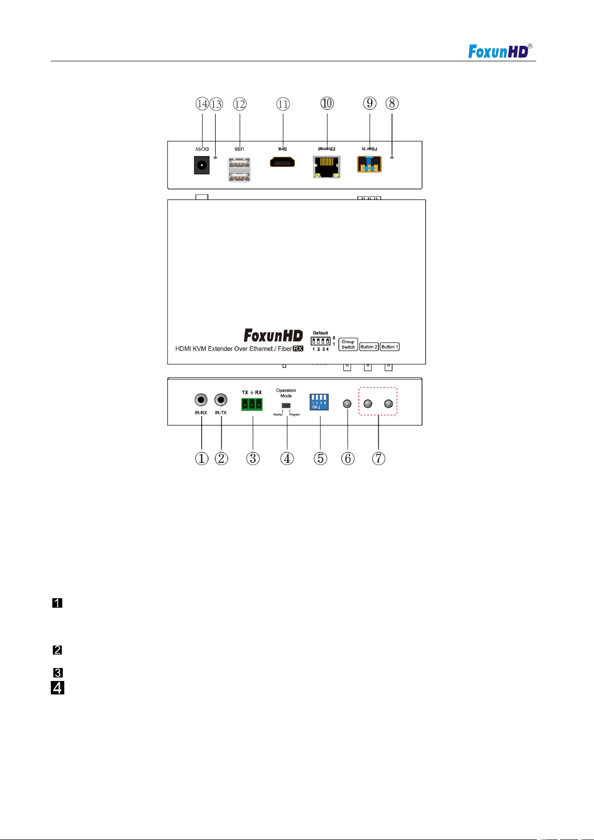
1) IR-RX port 2) IR-TX port
3) RS232 port 4) Normal: For serial over IP;
5) 4 bit Dip switch 6) Group Switch③
7) Button 1&2 ④ 8) Indicator of status ②
9) Fiber in 10)Ethernet port
11) HDMI output 12)USB
13)Power input indicator① 14)Power input port
A. Green LED: Link LED, when the connection has established over Cat5e/6 cable or Fiber
cable, the Green LED will illuminate.
B. Yellow LED: When the yellow LED is blinking, it indicates the connection has been established over Cat5e/6 cab
le.
When the green LED illuminates, it indicates the connection has been established between
transmitter and receiver over fiber cable.
After select the DIP switch, press “Group Switch” button for 1 second.
4 bits DIP Switch:
Use 4bits DIP switch to select 16 group ID (such as 0001, 0010, 0101 etc,)
EX37-RX
Please refer to 5.3.
5.3 Descriptions Buttons
Program: For serial control or getting the debug information
www.foxunhd.com
Operating Instructions
1. Check the power supply is unplugged.
2. Set up the group of the transmitter with the correspondent receiver for signal extension and display .
3. Connect the Transmitter to video source with HDMI cable,and connect Receiver to a monitor or display with HDMI cable.
4. Connect the USB cables from transmitter to PC,and connect the USB additional devices such as USB mouse,USB
keyboard and USB pen drive to Receiver.
5. Connect Transmitter and Receiver to the Ethernet switch with network cable.
6. Power on the Transmitter,Receiver and all the connected devices.
7. Power on and activate all the connected devices.
8. Connect the IR extension cable with transmitter and the IR receiver cable with Receiver for remote control.
(Host:Transmitter;client: Receiver)
Button state for Unicast Mode:HDMI Extender:
Default Mode will be highlighted in Green
CONNECT AND OPERATE
www.foxunhd.com
Operating Instructions
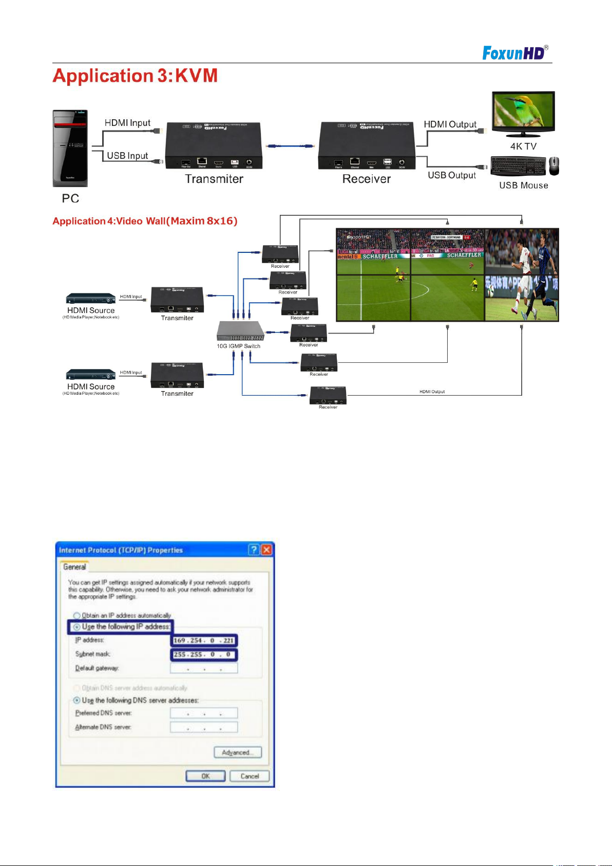
1. Assign a LAN IP address to the computer in the same subnet. The IP address default of the Transmitter
6.2 IP Configuration
The 4k HDMI &USB over IP Extender can configure via LAN in the same subnet.
and receiver is B class Networking:
169.254.xxx.xxx.
www.foxunhd.com
Operating Instructions
2. Connect the TX and RX with the Ethernet switch,Then connect the PC with the Ethernet switch.
1) Via “Node List”
2) The second way.
Figure 1.Internet Protocol(TCP/IP)Properties
Because this unit support DHCP,Different unit with different IP address of the factory reset,so the forst thing
we need know the IP address of each unit.
There is two way to get the IP address
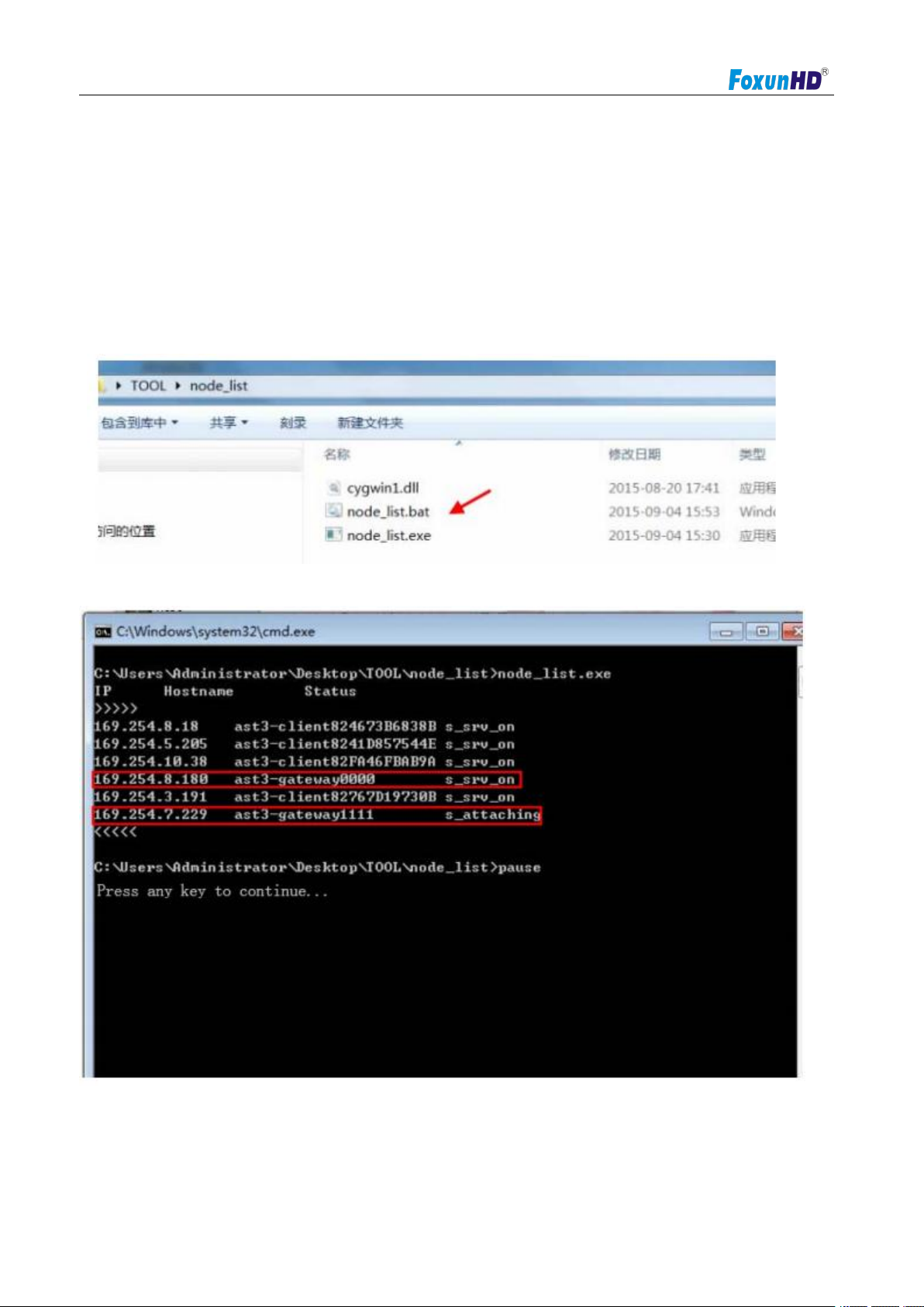
Open the “Node List”in the “Tool”file,press twice the “Node_list.bat” to enter the dialog box
Then we can see all the IP address of both the TX and RX show as bellow black dialog box.
Remark:If the IP address with “client”,it”s the IP address of the RX
If the IP address with”Gateway”,It’s the IP address the TX
www.foxunhd.com

Operating Instructions
3) After activation,the device information including the transmitter and receiver IP address will be show in
3.The administrator can input transmitter or receiver IP address into address bar of web browser(recommend the
7. WEB user interface configuration
Connect all devices with proper cables except video source,please refer to
the lower right corner.Remember the transmitter and receiver IP address on monitor screen and then plug
HDMI video source cable into transmitter.
Google Chrome) to the Extender Web UI
If link success,administrator will see the Web UI as shown in Figure 4.
7.1 System
www.foxunhd.com

Operating Instructions
The relevant information of the connected extender and setting
7.1.1[Version Information]
Indicating the firmware version and relevant information of the devices
7.1.2 [Update Firmware]
To update the firmware of the connected extender,please click on the [select file] to select the firmware and click
on[Upload] to upload the firmware and update accordingly.
www.foxunhd.com
 Loading...