

Page 1
User manual
document version 2.0
for DALImiw30 since versions: firmware 1.6 and hardware 4.0
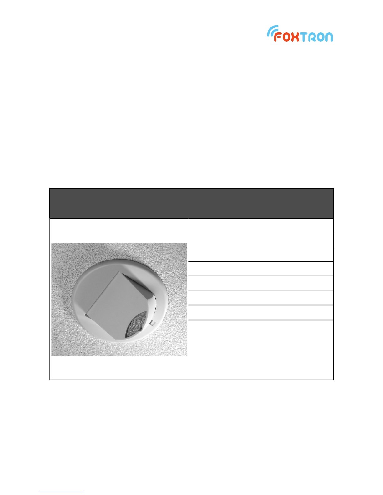
DALImiw30
Microwave sensor up to 2,6 meters height
Illuminance sensor
Regulation to constant level
Range 0-1000 lx
Powered from DALI bus or 230V
Can power DALI bus
1 www.foxtron.eu
Page 2

Technical specification
Bus DALI
Number of regulated groups 1
Power supply from DALI bus
(connected ~230V)
1 mA
Power supply from DALI bus (without
~230V)
15 mA
Maximal wires cross section 2,5 mm
2
Ingress protection IP20
Ambient working temperature 5 ÷ 50 °C
Storage temperature -10 ÷ 50 °C
Weight 100 g
Function
DALImiw30 is microwave combined motion and illumination sensor. It can regulate one
group of lights on the DALI bus. This group is controlled directly by DALImiw30 – no other
master is required. Based on movement the lights can be regulated to various lux levels.
Addressing and setup is done by software DALIconfig, which is downloadable for free on
the web of manufacturer.
Start or stop of the regulation or setting the desired illuminance level is done by standard
DALI messages from any DALI controller.
Control of the DALImiw30 is done by commands to regulated light group or to address of
the sensor or to broadcast. Regulated group of lights is the same as the group in which the
sensor is located. If the sensor is in no group all the lights on DALI bus are being regulated
(broadcast).
2 www.foxtron.eu
Page 3
Control of DALImiw30 is done by standard DALI messages. Their meaning for DALImiw30
is shown in following table:
DALI command Meaning to illuminance sensor DALImiw30
Direct arc power control, Off,
Up, Down, Step up, Step down,
Recall max level, Recall min
level, Step down and off, On and
step up
Stop of the regulation
GoToScene 0 – 15
Function is dependent on the setting Light sensor → Advanced settitng
→ Set response to scene recall
Automatic – Start of the regulation
OFF – stop of the regulation, regulated lights are switched off
Actual-auto – Start of the regulation. Current illuminance level is set
as desired level.
MASK – no function (stop of the regulation)
STORE DTR AS MIN LEVEL Set of the desired illuminance level
1)
QUERY MIN LEVEL Read of the desired illuminance level
1)
QUERY ACTUAL LEVEL Actual illuminance level
1)
Illuminance range is 0-1000lx.
1)
Data format is stated in the following table.
Illuminance data format
Data - 1byte (binary notation) Illuminance level [lx]
0000xxxx 0 – 15lx (step 1lx)
0001xxxx 16 – 46lx (step 2lx)
0010xxxx 48 – 108lx (step 4lx)
0011xxxx 112 – 232lx (step 8lx)
0100xxxx 240 – 480lx (step 16lx)
0101xxxx 496 – 976lx (step 32lx)
0110xxxx 1008 – 1968lx (step 64lx)
Illuminance level is set and read as an 8bit number in format
0 E E E M M M M
And its value is given according to the relation
2
4 +E
−16+2E∗M
Example
65 = 0x41 = 01000001b ~ 256lx
50 = 0x32 = 00110010b ~ 128lx
3 www.foxtron.eu
Page 4

luminance sensor
DALImiw30 allows direct control of luminaires to a constant level of illumination.If the
motion sensor is also on, it is possible to set various illumination values for the presence
and absence value. The light sensor can be deactivated and the motion sensor will light
the luminaire to a constant preset value instead of the ambient light control. The
illumination sensor measures 0-1000lx.
Configuration
Ambient light control
Turn on the ambient light control. In the case that ambient light control is off, the
luminaires are switched to the preset constant level. (Presence/Absence value)
Desired level Desired level in the case of presence mode. Possible setup range is 5-1000lx.
Desired level in
absence mode
Desired level in the case of absence mode. Possible setup range is 5-1000lx.
Value 0 lx means that it will be dimmed to absolute Absence value.
Control speed
Regulation speed. The most common setting is 3. Lower values mean faster
regulation, higher values mean slower regulation.
Switch-on level
First value send at the beginning of the regulation.
Minimum level sends the command Recall min level
Maximum level sends the command Recall max level
Calculated will compute the value dependent on the surrounding illuminance.
Flying – flying start
Enable dimming off
If there is enough illuminance, it allows luminaires to switch off. If this function is
disabled luminaires remain at a minimum level.
Treshold
(Enable dimming off)
Percent excess light to activate the function „Enable dimming off“.
Example: 150% means 50% excess.
Delay time
(Enable dimming off)
Time which must be excess illuminance before the ligts are switched off.
Motion sensor
The motion sensor serves for automatically dimming/switching off the lights dependent on
the presence/absence of people in detected area. Luminaires can be light up to a defined
value or they can be controlled by a light sensor.
4 www.foxtron.eu
Page 5

Configuration
Operating mode
Enable – Motion detection is on. When movement lights are turned on, in
absence lights are dimmed or switched off.
Enable (only off) – Lights must be turned on manually, if absence lights are
dimmed or switched off and must be switched on manually again.
Disable – Motion detection is off.
Power on behaviour
Possibility to send command when the power supply is connected to
DALImiw30.
No action – Power on function is off.
Maximum level – Command Recall Max Level is sent
Off – Off command is sent
1: Presence value
Absolute level at which are luminaires switched on in presence mode. Setting
range is 0-100%. In the case of ambient light control is this parameter not
used.
2: Absence value
Absolute level at which are luminaires dimmed in the case of absence. Setting
range is 0-100%. In the case of ambient light control is this parameter not
used.
3: Fade time (on) Dimming speed to „1: Presence value“
4: Run-on time The time without any movement, after which is activated absence mode.
5: fade time (to absence) Dimming speed to „2: Absence value“
6: Switch-off delay Absence time, after which are luminaires dimmed or switched off. If the
function “never off” is activated luminaires remain on level „2: Absence value“.
7: fade time (to off) Dimming speed to off „6: Switch-off delay“.
Dead time (manual off) The time after manual “OFF” in which is the sensor inactive.
Sensitivity
Sensitivity of the sensor to movement. Setting range 0-250. Lower number
means higher sensitivity. For values lower than 70 there might be problems
with false movement detections.
LED function
Auto – Light signalization in the sensor is on when detecting movement. When
ambient light control is on the signalization is off.
Off – Light signalization is off.
On – Light signalization is on.
Dead time – Time after manual “OFF” (for example from a push button) in which the
sensor does not react on any movement. It allows to leave a room without switching
luminaires on.
5 www.foxtron.eu
Page 6

Terminals connection
Terminal designation description
DA DALI bus, two interchangeable conductors
OUT+ / OUT- Output for DALI bus power
N Neutral
L Live
Lex Input from external sensor (live)
Power supply
DALIpir20 has optional power of a DALI bus. DALI bus power is on the terminals OUT+
and OUT-. If there is a need to power DALI bus from DALIpir20 it is necessary to connect
one DA terminal with OUT+ terminal and the other DA terminal with OUT- terminal. DA
terminals are interchangeable. Power supply of DALI bus can provide current up to 50mA
which allows to power up to 25 DALI ballasts. For this function the DALIpir20 must be
powered from ~230V. If the DALI bus is powered by any other supply, terminals OUT+ and
OUT- are not connected.
External input
Lex is external input to which can be external sensor connected (which is not connected to
DALI bus). Using those external sensors the detection range of DALImiw30 can be
extended.
6 www.foxtron.eu
Page 7

Installation
Sensor DALImiw30 has two basic installation possibilities:
1) Cavity ceiling installation
2) Surface installation using special mounting kit
It is necessary to choose sensor position with respect to following conditions:
• No light source (controlled / not controlled by sensor) should point directly to sensor
• Sensed area should not point towards the windows
• In sensed area should not be any shiny objects which reflection affects the sensor
• In case of installation multiple sensors in one room their sensed area should not
overlap
• Maximal mounting height is 2.6 meters
7 www.foxtron.eu
Page 8

Detection diagrams
8 www.foxtron.eu
Page 9

Dimensions [mm]
tel: +420 274 772 527
e-mail: info@foxtron.cz
web: www.foxtron.eu
9 www.foxtron.eu
 Loading...