

Fox Thermal FT2A User Manual

Fox Thermal
THERMAL MASS FLOW METER
& TEMPERATURE TRANSMITTER
Model FT2A
Modbus & BACnet
Precision Mass Flow Measurement
www.foxthermal.com | 399 Reservation Road Marina, CA. 93933
An ON
I
CON Brand
105435
Rev. D

Modbus/BACnet
Notice
equipment require repair or adjustment beyond the procedures given herein,
FOX THERMAL
This publication must be read in its entirety before performing any
operation. Failure to understand and follow these instructions could result
in serious personal injury and/or damage to the equipment. Should this
contact the factory at:
FOX THERMAL INSTRUMENTS, INC.
399 RESERVATION ROAD
MARINA, CA 93933
TELEPHONE: 831-384-4300
FAX: 831-337-5787
EMAIL: SERVICE@FOXTHERMAL.COM
Download Technical Data Sheets from our website:
www.foxthermal.com
Fox Thermal believes that the information provided herein is accurate
however be advised that the information contained herein is NOT
a guarantee for satisfactory results. Specically, this information is
neither a warranty nor guarantee, expressed or implied, regarding
performance; merchantability; tness; or any other matter with
respect to the products; nor recommendation for the use of the
product/process information in conict with any patent. Please note
that Fox Thermal reserves the right to change and/or improve the
product design and specication without notice.
Fox FT2A Manuals:
• Model FT2A Instruction Manual
• Fox FT2A View™ Instruction Manual
• Fox FT2A Anybus Manual
2

Modbus/BACnet
Table Of Contents
1. Modbus Introduction Page 4
2. Modbus Protocol Page 4
3. RS485 Wiring for Modbus Page 5
4. FT2A Commands Supported by Modbus Page 6
5. Modbus Programming Page 12
6. BACnet Introduction Page 17
7. BACnet Protocol Page 16
8. RS485 Wiring for BACnet MS/TP Page 18
9. BACnet Programming Page 19
TABLE OF CONTENTS
10. Glossary of Terms and Abbreviations Page 24
11. Index Page 25
3

Model FT2A
Modbus/BACnet
Model FT2A
Modbus Introduction
Scope
Thank you for purchasing the model FT2A thermal gas mass ow meter from Fox Thermal.
The model FT2A is one of the most technically advanced ow meters in the world. Extensive
engineering effort has been invested to deliver advanced features, accuracy measurement
performance and outstanding reliability.
This document describes the Modbus implementation using RS485 serial communication
physical layer for the Fox Thermal FT2A mass ow meter based on the Modicon Modbus
Protocol (PI-MBUS-300 Rev. J).
Modbus Protocol
MODBUS Protocol is an application layer messaging protocol that provides client/sever
communications between devices. MODBUS is a request/reply protocol and offers services
specied by function codes.
The size of the MODBUS Protocol Data Unit is limited by the size constraint inherited from the
rst MODBUS implementation on Serial Line network (max. RS485 Application Data Unit = 256
bytes).
MODBUS PROTOCOL
Therefore, MODBUS PDU for serial line communication = 256 – Server address (1 byte) – CRC
(2 bytes) = 253 bytes.
RS485 ADU = 253 + Server address (1 byte) + CRC (2 bytes) = 256 bytes.
For more information on MODBUS go to the web site http://www.modbus.org/.
Command Request:
<Meter Address> <Function code> <Register start address high> <Register start address
low> <Register count high> <Register count low> <CRC high> <CRC low>
Command Response:
<Meter Address> <Function code> <Data byte count> <Data register high> <Data
register low> ... <Data register high> <Data register low> <CRC high> <CRC low>
Note: The data in shown in brackets < > represents one byte of data.
i
4
Modbus/BACnet
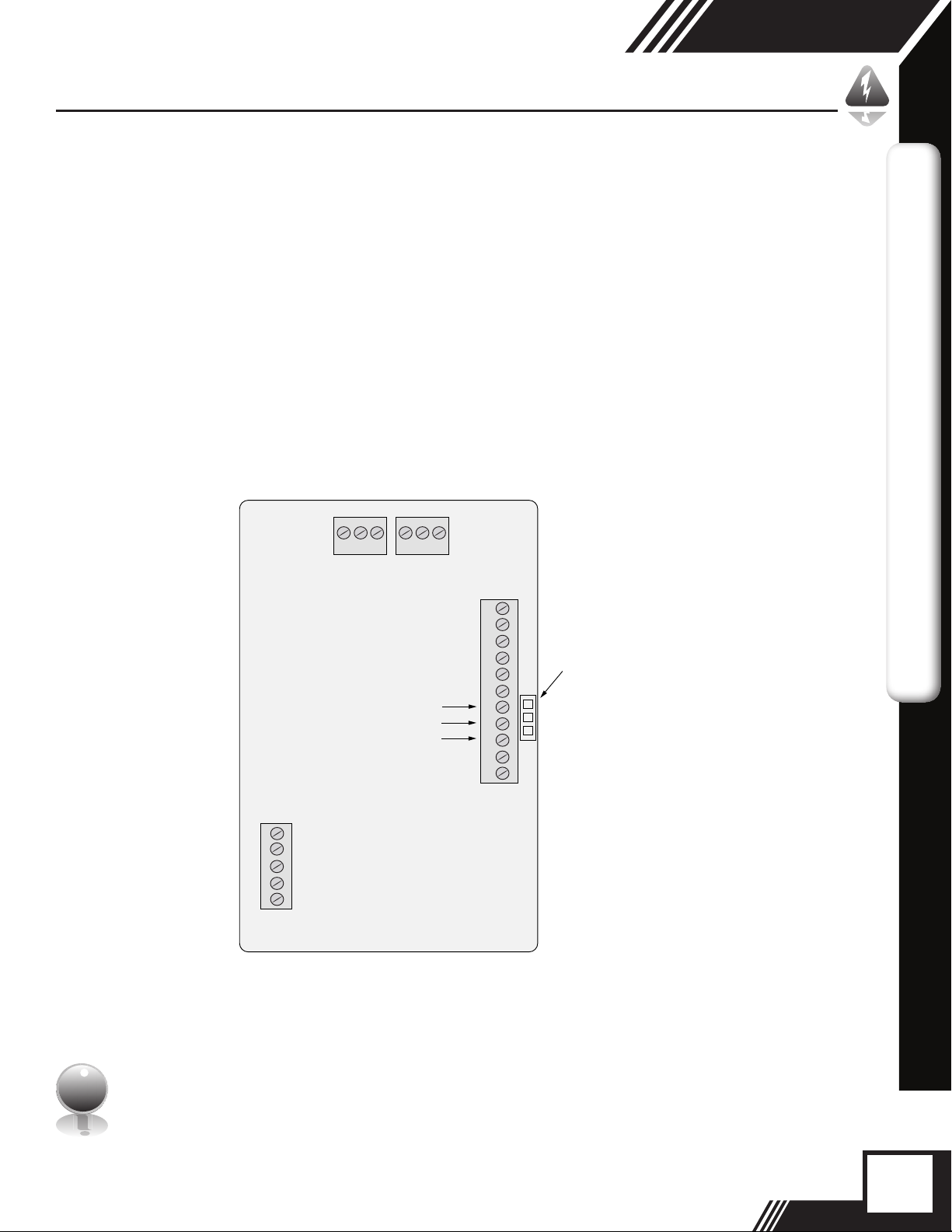
RS485 Wiring: Modbus
RS485 Wiring for Modbus
Wiring connections are made to terminal block TS2 for Modbus communication.
The Tx/Rx+ signal connects to pin 7, Tx/Rx- connects to pin 8 and communication common to
pin 9 as shown in Figure 3.1.
Termination Resistor
Connect a termination resistor across the receive/transmit signals of the last device on the
Modbus communication line. To connect the 121 ohm termination resistor on the FT2A, set
jumper W1 to the TERM position.
Disconnect the termination resistor on all other external Modbus devices. The termination
resistor of the FT2A is disconnected by setting jumper W1 to the NC (Not Connected) position.
Fig. 3.1: Modbus Wiring
MODBUS WIRING
1 2 3
TS7 TS1
Communication Common
TS8
1
2
3
4
5
1 2 3
Tx/Rx (+)
-
Tx/Rx (
TS2
1
1
2
3
4
5
W1
6
)
7
8
9
10
11
Pin 1 of termination resistor header
W1
NC (Termination resistor Not Connected)
}
}
TERM (Termination resistor installed)
Note: W1 jumper will either be in the NC or TERM position. It should be in the TERM
position on the last meter in the Modbus daisy chain.
i
5

Modbus/BACnet
FT2A Commands Supported by Modbus
FT2A Commands Supported
The FT2A supports the following commands:
1) Command 03: Read holding registers
2) Command 04: Read input register.
3) Command 06: Preset single register
Read Holding Registers (command 03)
This command reads the basic variable from the FT2A and has the following format:
Request:
<Meter Address> <Command code=03> <Register start address high> <Register start
address low> <Register count high> <Register count low> <CRC high> <CRC low>
Response:
<Meter Address> <Command code=03> <Byte count> <Data high><Data low> ... <Data
high><Data low> <CRC high> <CRC low>
Example:
Request data register at starting address 0x0000 and specifying only 1 register
MODBUS - FT2A COMMANDS
<0x01> <0x03> <0x00> <0x00> <0x00> <0x01> <0x0a> <0x84>
Response:
<0x01> <0x03> <0x02> <xx> <xx> <CRC high> <CRC low>
Where xx xx is the data register value.
Table 4.1: FT2A Modbus Holding Registers
Register
Address
0x00 40001 Flow in Eng units (low) No Mass ow in selected units
0x01 40002 Flow in Eng units (high) No
0x02 40003 Total (low) No Total in selected units
0x03 40004 Total (High) No
0x04 40005 Temperature (low) *10 Temperature in selected units
0x05 40006 Temperature (high) *10
0x06 40007 Elapsed time (low) *10 Elapsed time in hours * 10
0x07 40008 Elapsed time (high) *10
0x08 40009 Velocity (Low) No Velocity in nm/hr
Modbus
Address
Data Type Scaling Comment
* 10
6

FT2A Commands Supported by Modbus
Modbus/BACnet
Register
Address
0x09 40010 Velocity (high) No
0x0A 40011 Flow in Eng units * 10 10 Mass ow in selected units * 10
0x0B 40012 Flow in Eng units *100 100 Mass ow in selected units *
0x0C 40013 Total *100 100 Total in selected units * 100
0x0D 40014 Total2 (low, 2 gas curves only) No Total #2 for 2 gas curves
0x0E 40015 Total2 (high, 2 gas curves only) No Total #2 for 2 gas curves
0x0F 40016 Status No Status
0x10 40017 Spare/ Not used
0x11 40018 Control Register (Write Only) No Control Register
0x12 40019 Spare/ Not used
0x13 40020 Flow in Eng units (oat, upper 16 bits) No Mass ow in selected units
0x14 40021 Flow in Eng units (oat, lower 16 bits) No Mass ow in selected units
0x15 40022 Total in Eng units (oat, upper 16 bits) No Total in selected units
0x16 40023 Total in Eng units (oat, lower 16 bits) No Total in selected units
0x17 40024 Total#2 for 2 gas curve (oat, upper 16 bits) No Total in selected units
0x18 40025 Total#2 for 2 gas curve (oat, lower 16 bits) No Total in selected units
0x19 40026 Temperature in selected units (oat, upper 16 bits) No Temperature in selected units
0x1A 40027 Temperature in selected units (oat, lower 16 bits) No Temperature in selected units
0x1B 40028 Elapsed time in hours (oat, upper 16 bits) No Elapsed time in hours
0x1C 40029 Elapsed time in hours (oat, lower 16 bits) No Elapsed time in hours
0x1D 40030 Velocity in selected units (oat, upper 16 bits) No Velocity in selected units
0x1E 40031 Velocity in selected units (oat, lower 16 bits) No Velocity in selected units
0x1F 40032 Spare/ Not used
0x20 40033 Spare/ Not used
0x21 40034 Spare/ Not used
0x22 40035 Spare/ Not used
0x23 40036 Spare/ Not used
0x24 40037 Total 24 hrs, Last total record, low register No Tot24hrs: Last total record
0x25 40038 Total 24 hrs, Last total record, high register No Tot24hrs: Last total record
0x26 40039 Total 24 hrs, Current Day (0-6) No Tot24hrs: Current Day
0x27 40040 Total 24 hrs, Current Hour (0-23) No Tot24hrs: Current Hour
0x28 40041 Total 24 hrs, Record day 1, low register No Tot24hrs: Record day 1
0x29 40042 Total 24 hrs, Record day 1, high register No Tot24hrs: Record day 1
0x2A 40043 Total 24 hrs, Record day 2, low register No Tot24hrs: Record day 2
0x2B 40044 Total 24 hrs, Record day 2, high register No Tot24hrs: Record day 2
0x2C 40045 Total 24 hrs, Record day 3, low register No Tot24hrs: Record day 3
0x2D 40046 Total 24 hrs, Record day 3, high register No Tot24hrs: Record day 3
0x2E 40047 Total 24 hrs, Record day 4, low register No Tot24hrs: Record day 4
0x2F 40048 Total 24 hrs, Record day 4, high register No Tot24hrs: Record day 4
Modbus
Address
Data Type Scaling Comment
100
MODBUS - FT2A COMMANDS
7

Modbus/BACnet
FT2A Commands Supported by Modbus
Register
Address
0x30 40049 Total 24 hrs, Record day 5, low register No Tot24hrs: Record day 5
0x31 40050 Total 24 hrs, Record day 5, high register No Tot24hrs: Record day 5
0x32 40051 Total 24 hrs, Record day 6, low register No Tot24hrs: Record day 6
0x33 40052 Total 24 hrs, Record day 6, high register No Tot24hrs: Record day 6
0x34 40053 Total 24 hrs, Record day 7, low register No Tot24hrs: Record day 7
0x35 40054 Total 24 hrs, Record day 7, high register No Tot24hrs: Record day 7
0x36 40055 Total 24 hrs, Last Total, low register No Tot24hrs: Last Total
0x37 40056 Total 24 hrs, Last Total, high register No Tot24hrs: Last Total
0x38 40057 Reserved No
0x39 40058 Reserved No
0x3A 40059 Reserved No
0x3B 40060 Reserved No
0x3C 40061 Reserved No
0x3D 40062 Reserved No
0x3E 40063 Reserved No
0x3F 40064 Reserved No
0x40 40065 Reserved No
0x41 40066 Reserved No
MODBUS - FT2A COMMANDS
0x42 40067 Reserved No
0x43 40068 Reserved No
0x44 40069 Reserved No
Modbus
Address
Data Type Scaling Comment
* The data in registers with scaling must be multiplied by 10 or 100 as indicated to be scaled properly.
Note: Registers A, B & C are provided to get more resolution for low ow and total.
When value exceeds the 16 bit registers, they will be frozen with all 16 bits set. It is also
i
possible to use the velocity to calculate the ow in engineering units by using the pipe
area and conversion factor for the selected units.
8
 Loading...