

Page 1

Foxtech VD16-E Radio Controller
User Manual
V1.0
2019.09
Page 2
VD16-E Radio Control System User Manual
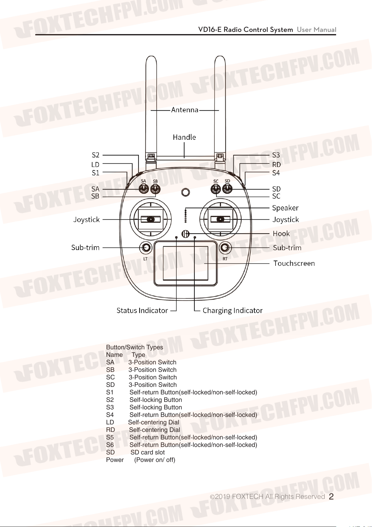
Button/Switch Types
Name Type
SA 3-Position Switch
SB 3-Position Switch
SC 3-Position Switch
SD 3-Position Switch
S1 Self-return Button(self-locked/non-self-locked)
S2 Self-locking Button
S3 Self-locking Button
S4 Self-return Button(self-locked/non-self-locked)
LD Self-centering Dial
RD Self-centering Dial
S5 Self-return Button(self-locked/non-self-locked)
S6 Self-return Button(self-locked/non-self-locked)
SD SD card slot
Power (Power on/ off)
2019 FOXTECH All Rights Reserved
©
2
Page 3
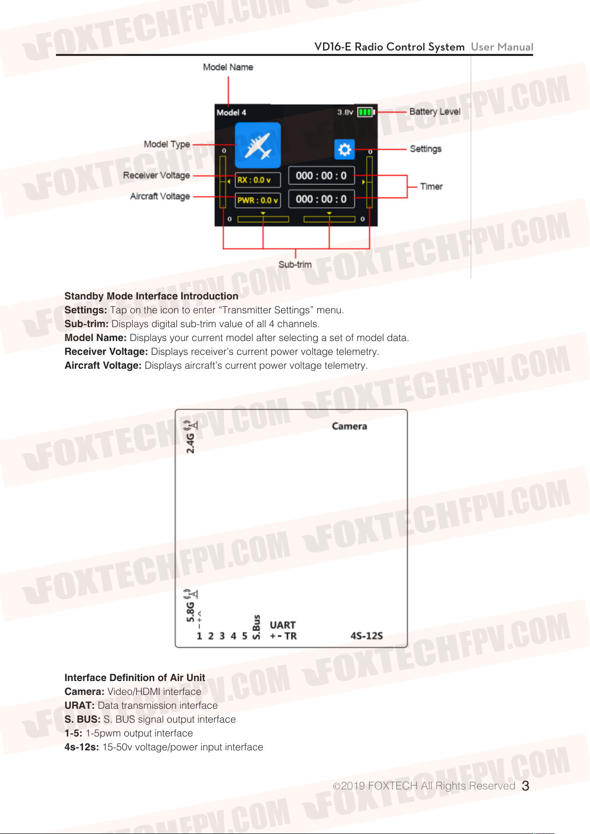
Standby Mode Interface Introduction
Settings:
Sub-trim:
Model Name:
Receiver Voltage:
Aircraft Voltage:
Tap on the icon to enter “Transmitter Settings” menu.
Displays digital sub-trim value of all 4 channels.
Displays your current model after selecting a set of model data.
Displays receiver’s current power voltage telemetry.
Displays aircraft’s current power voltage telemetry.
VD16-E Radio Control System User Manual
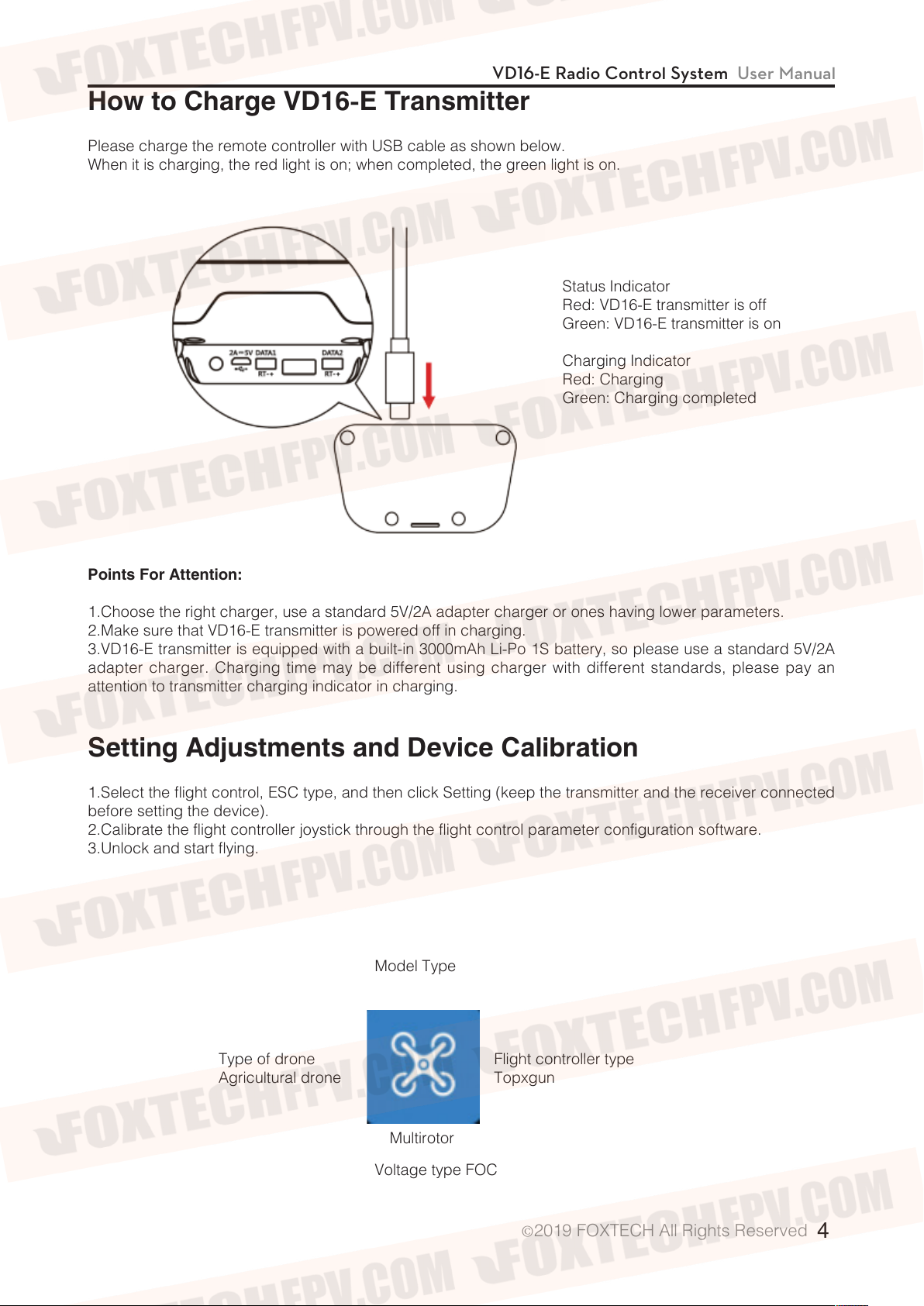
Interface Definition of Air Unit
Camera:
URAT:
S. BUS:
1-5:
4s-12s:
Video/HDMI interface
Data transmission interface
S. BUS signal output interface
1-5pwm output interface
15-50v voltage/power input interface
2019 FOXTECH All Rights Reserved
©
3
Page 4
VD16-E Radio Control System User Manual
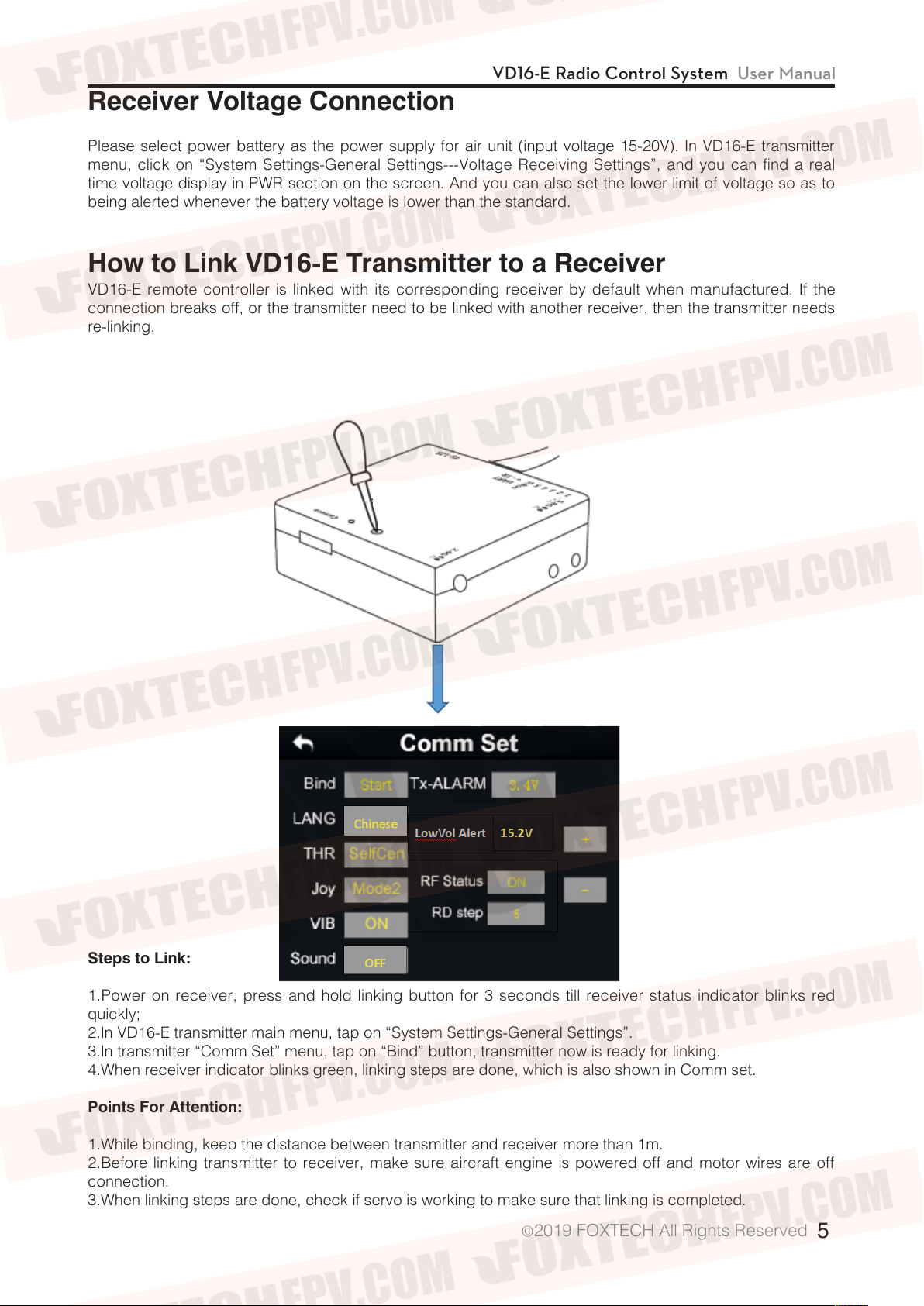
How to Charge VD16-E Transmitter
Please charge the remote controller with USB cable as shown below.
When it is charging, the red light is on; when completed, the green light is on.
Status Indicator
Red: VD16-E transmitter is off
Green: VD16-E transmitter is on
Charging Indicator
Red: Charging
Green: Charging completed
Points For Attention:
1.Choose the right charger, use a standard 5V/2A adapter charger or ones having lower parameters.
2.Make sure that VD16-E transmitter is powered off in charging.
3.VD16-E transmitter is equipped with a built-in 3000mAh Li-Po 1S battery, so please use a standard 5V/2A
adapter charger. Charging time may be different using charger with different standards, please pay an
attention to transmitter charging indicator in charging.
Setting Adjustments and Device Calibration
1.Select the flight control, ESC type, and then click Setting (keep the transmitter and the receiver connected
before setting the device).
2.Calibrate the flight controller joystick through the flight control parameter configuration software.
3.Unlock and start flying.
Model Type
Type of drone
Agricultural drone
Multirotor
Voltage type FOC
Flight controller type
Topxgun
2019 FOXTECH All Rights Reserved
©
4
Page 5
VD16-E Radio Control System User Manual
Receiver Voltage Connection
Please select power battery as the power supply for air unit (input voltage 15-20V). In VD16-E transmitter
menu, click on “System Settings-General Settings---Voltage Receiving Settings”, and you can find a real
time voltage display in PWR section on the screen. And you can also set the lower limit of voltage so as to
being alerted whenever the battery voltage is lower than the standard.
How to Link VD16-E Transmitter to a Receiver
VD16-E remote controller is linked with its corresponding receiver by default when manufactured. If the
connection breaks off, or the transmitter need to be linked with another receiver, then the transmitter needs
re-linking.
Steps to Link:
1.Power on receiver, press and hold linking button for 3 seconds till receiver status indicator blinks red
quickly;
2.In VD16-E transmitter main menu, tap on “System Settings-General Settings”.
3.In transmitter “Comm Set” menu, tap on “Bind” button, transmitter now is ready for linking.
4.When receiver indicator blinks green, linking steps are done, which is also shown in Comm set.
Points For Attention:
1.While binding, keep the distance between transmitter and receiver more than 1m.
2.Before linking transmitter to receiver, make sure aircraft engine is powered off and motor wires are off
connection.
3.When linking steps are done, check if servo is working to make sure that linking is completed.
2019 FOXTECH All Rights Reserved
©
5
Page 6
VD16-E Radio Control System User Manual
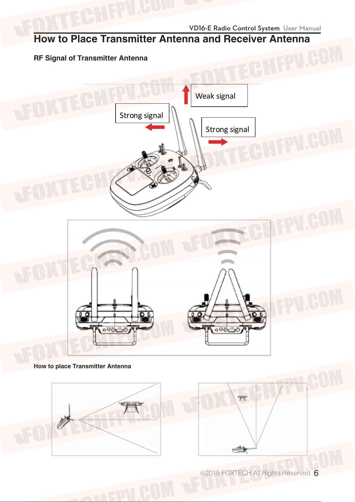
St r ong signal
Weak signal
St r ong signal
How to Place Transmitter Antenna and Receiver Antenna
RF Signal of Transmitter Antenna
How to place Transmitter Antenna
2019 FOXTECH All Rights Reserved
©
6
Page 7
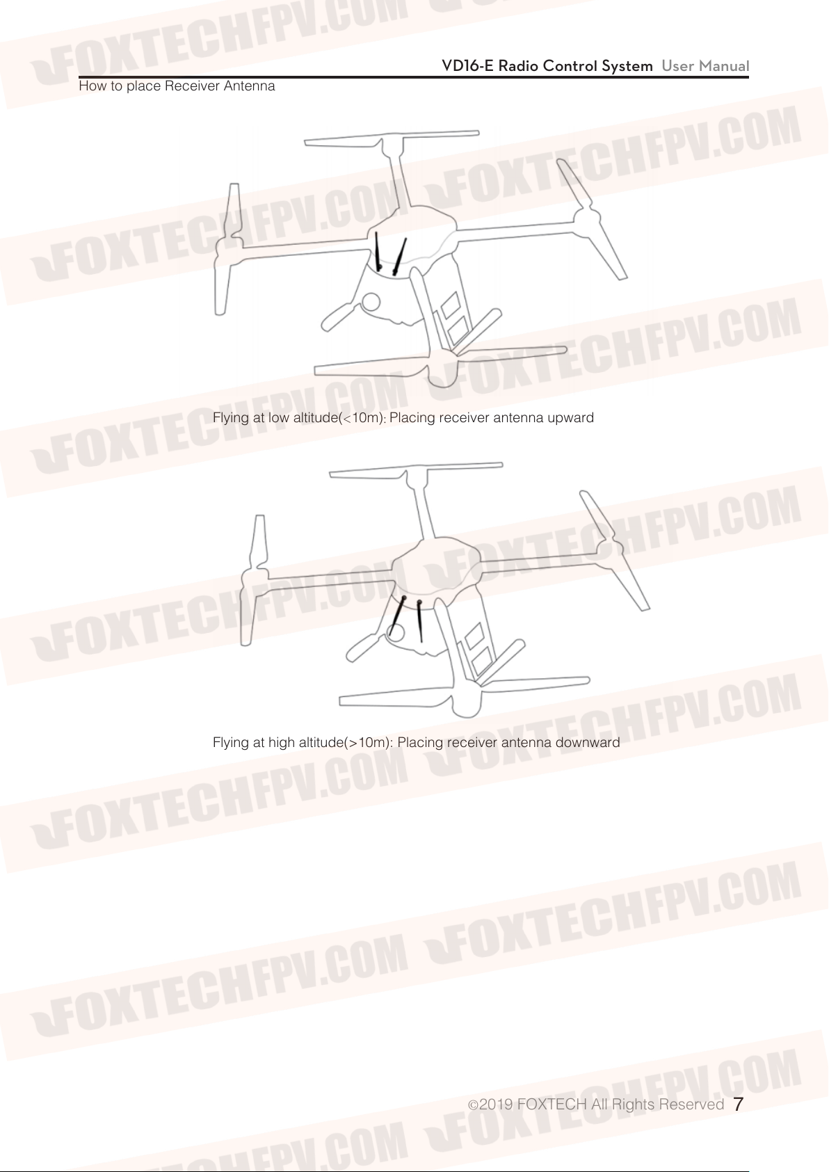
How to place Receiver Antenna
Flying at low altitude(<10m): Placing receiver antenna upward
VD16-E Radio Control System User Manual
Flying at high altitude(>10m): Placing receiver antenna downward
2019 FOXTECH All Rights Reserved
©
7
Page 8

VD16-E Radio Control System User Manual
Steps to Set Datalink
1.Connect the UART port of air unit to flight controller datalink port with the flight controller connection cable
in the package.
2.Select the right flight controller type.
3.On a mobile device, search for an external Bluetooth device, choose the one called “02A*******”, which is
of ten numbers. Enter the corresponding password “1234”, and pair it with the device.
* If you select this device for Topxgun flight controller, please pair it with the Bluetooth device exclusive for
Topxgun.
Paring steps:
In “Remote Control” menu, tap on “video/Data Transmission” Settings-- “Bluetooth” Settings and select
Topxgun, which is “TOPGUN 02A*******”. When it is successfully linked, select it as the connecting method.
4.Turn on the ground station APP, check for the paired Bluetooth device and pair it with the ground station.
Instructions on HD Video transmission System
1.Link ports of antenna, camera and power to the port of air unit.
2.Connect mobile phone and remote control with the data cable, which is included in the package. And
make sure remote controller is powered on.
3.Download an Video display APP.
* Due to the android system setting, please manually open the permission of the floating window function of
the software for the first time to ensure normal use of the floating window function.
4.Turn on USB network sharing of mobile devices, and get real-time video on “Video Display ” APP.
* Since USB needs to transfer images, please use Bluetooth for ground station connection.
2019 FOXTECH All Rights Reserved
©
8
 Loading...