

Page 1
THEA-130 / 160
Sprayer Drone
User Manual
V1.0
2019.04
Page 2
Contents
THEA-130 / 160 Sprayer Drone User Manual
Disclaimer
Flight Operation
Environmental Requirements
Pre-ight Check
Compass Clibration
Work in Manual Stabilization Mode
Work in Manual Plus (AB point) Mode
Repair and Maintenance
Replace the Propeller
Replace the Motor
Replace the ESC
Replace Nozzles
Replace the Pump
3
5
5
5
5
6
7
11
11
11
11
11
11
Cleaning After Use
System Introduction
System Characteristic
Introduction to Flight Mode
Installation and Connection
System Supporting List
Flight Controller System Connection Diagram
Interface Denition
Status Indicator Description
Remote Control Equipment
Receiver
Remote Control Conguration
Unlocking and Locking for Flight Control
12
13
13
14
15
15
15
16
18
20
20
20
21
ESC Calibration (Electronic Speed Controller)
22
©
2019 FOXTECH All Rights Reserved
1
Page 3
THEA-130 / 160 Sprayer Drone User Manual
Remote Control Protection
Protect Content
Return Logic
Remote Control Security
Data Link Loss of Control
Voltage Detection and Protection
Area Limited Protection
Ground Station Setting
Equipment Connection
Function Introduction
Route Planning
Ready to Take Off
RTK Use Instructions
23
23
24
24
25
25
25
26
26
27
32
36
37
Concise Operation Process
Precautions
Failure Analysis
After-sales Service
Installation of Ground Station and Drivers
Installation
40
41
42
43
44
44
©
2019 FOXTECH All Rights Reserved
2
Page 4
THEA-130 / 160 Sprayer Drone User Manual
Disclaimer
1. To protect the legitimate rights and interests of users, please read the instructions, disclaimers and safety
instructions provided with this product before using this product. Know your legal rights, responsibilities,
and safety instructions; otherwise you may incur property damage, safety incidents, and personal safety
hazards. The company reserves the right to update the above documents. Please be sure to operate this
product in accordance with the instructions and safety instructions.
2. The company will not be responsible for any violation of the law that occurs directly or indirectly by the
user.
3. This product is not suitable for people under the age of 18 and other people who do not have full civil
capacity. Please avoid the above-mentioned people from contacting this product. In the case where the
above-mentioned persons appear, please pay special attention to the operation.
4. Once you start using this product, you are deemed to have read, understood, approved and accepted all
terms and conditions of the product's instructions, disclaimers and safety instructions. The user is committed
to being responsible for his or her actions and all consequences arising by this. The User undertakes to use
the Product solely for legitimate purposes and agrees to these Terms and any relevant policies or guidelines
that may be established by the Company.
5. In the process of using this product, please strictly observe and implement the requirements including but
not limited to the instructions and safety instructions. All personal injury, accident, property damage, legal
disputes, and other adverse events that cause conflicts of interest caused by breach of safety instructions
or force majeure factors shall be borne by the user and the company shall not bear any responsibility.
6. We do not provide any technical support and security commitments in the following situations:
1) Units or individuals who obtain this product through informal agents or irregular channels;
2) Products that are not authorized to be modified, commissioned or replaced;
3) Warranty card, serial number or flight data are lost;
4) Personal injury and property damage due to personal operation errors.
©
2019 FOXTECH All Rights Reserved
3
Page 5
THEA-130 / 160 Sprayer Drone User Manual
1. To protect the legitimate rights and interests of users, please read the instructions, disclaimers and safety
instructions provided with this product before using this product. Know your legal rights, responsibilities,
and safety instructions; otherwise you may incur property damage, safety incidents, and personal safety
hazards. The company reserves the right to update the above documents. Please be sure to operate this
product in accordance with the instructions and safety instructions.
2. The company will not be responsible for any violation of the law that occurs directly or indirectly by the
user.
3. This product is not suitable for people under the age of 18 and other people who do not have full civil
capacity. Please avoid the above-mentioned people from contacting this product. In the case where the
above-mentioned persons appear, please pay special attention to the operation.
4. Once you start using this product, you are deemed to have read, understood, approved and accepted all
terms and conditions of the product's instructions, disclaimers and safety instructions. The user is committed
to being responsible for his or her actions and all consequences arising by this. The User undertakes to use
the Product solely for legitimate purposes and agrees to these Terms and any relevant policies or guidelines
that may be established by the Company.
5. In the process of using this product, please strictly observe and implement the requirements including but
not limited to the instructions and safety instructions. All personal injury, accident, property damage, legal
disputes, and other adverse events that cause conflicts of interest caused by breach of safety instructions
or force majeure factors shall be borne by the user and the company shall not bear any responsibility.
6. We do not provide any technical support and security commitments in the following situations:
1) Units or individuals who obtain this product through informal agents or irregular channels;
2) Products that are not authorized to be modified, commissioned or replaced;
3) Warranty card, serial number or flight data are lost;
4) Personal injury and property damage due to personal operation errors.
©
2019 FOXTECH All Rights Reserved
4
Page 6
THEA-130 / 160 Sprayer Drone User Manual
Flight Operation
Environmental Requirements
-In an open environment, there is no occlusion, so as not to affect the search for satellite signals.
-The wind is less than 5 (≤8m/s).
-There is no strong magnetic field around, such as high-voltage lines, magnetite, etc., so as not to affect the
normal operation of the magnetic compass.
Pre-ight Check
-Make sure that the drone battery, remote control battery, and ground station (Android phone) are fully
charged.
-Make sure the drone battery is fixed.
-Ensure that the components are tightly fastened and that all screws are not loose.
-Make sure all connections are correct.
-Make sure that the propellers are not damaged, securely mounted, in the right direction, and that it works
correctly. All arms and propellers are fully deployed and the arm sleeve is locked.
-Make sure the spray system is free of impurities and can work properly.
Compass Clibration
Compass calibration must be performed before first use, otherwise the system may not work properly, which
may affect flight safety.
Do not calibrate in areas with strong magnetic or large blocks of metal, such as high voltage lines,
magnetic mines, parking lots, and buildings near steels.
Do not carry magnetic substances with your body during calibration, such as mobile phones
If the compass is calibrated indoors, remember to recalibrate when using it outdoors to prevent the
magnetic field difference between the two areas and cause abnormal flight data.
The position of the Earth's magnetic field is different. Please recalibrate the compass when replacing
a remote area.
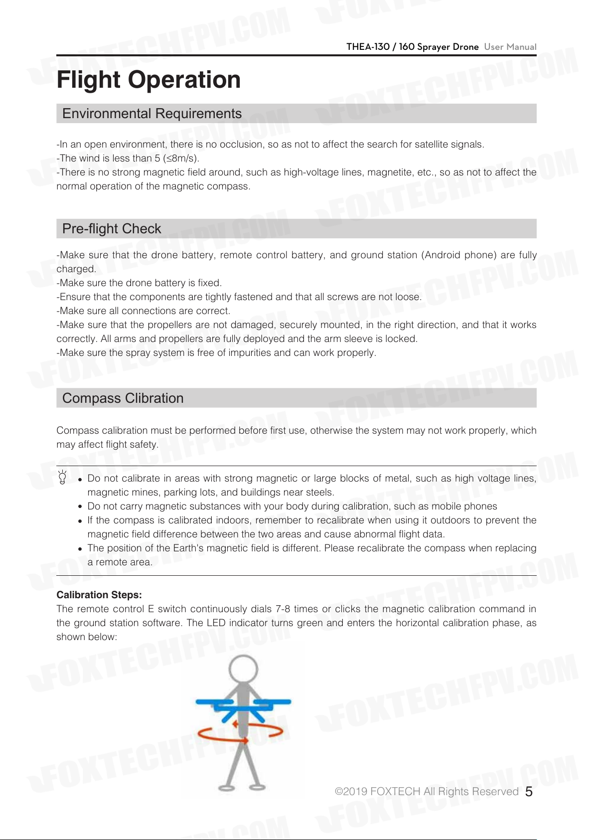
Calibration Steps:
The remote control E switch continuously dials 7-8 times or clicks the magnetic calibration command in
the ground station software. The LED indicator turns green and enters the horizontal calibration phase, as
shown below:
©
2019 FOXTECH All Rights Reserved
5
Page 7
THEA-130 / 160 Sprayer Drone User Manual
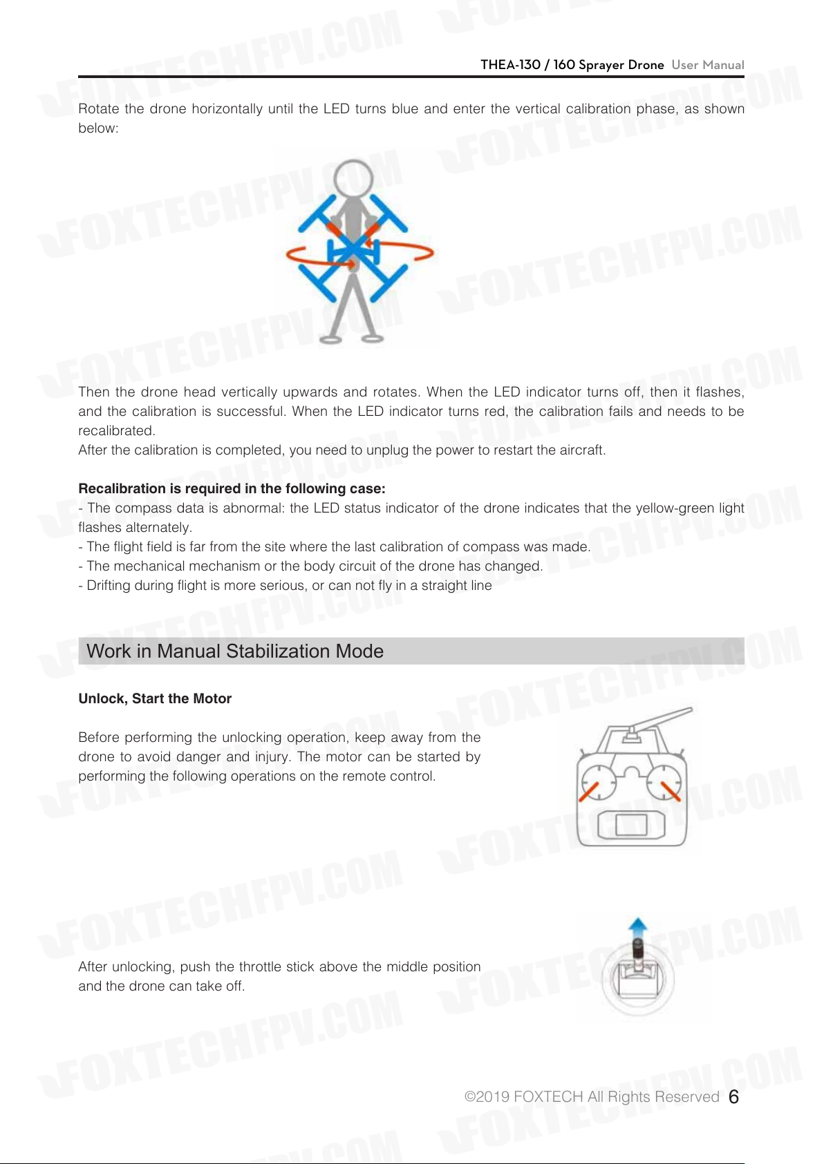
Rotate the drone horizontally until the LED turns blue and enter the vertical calibration phase, as shown
below:
Then the drone head vertically upwards and rotates. When the LED indicator turns off, then it flashes,
and the calibration is successful. When the LED indicator turns red, the calibration fails and needs to be
recalibrated.
After the calibration is completed, you need to unplug the power to restart the aircraft.
Recalibration is required in the following case:
- The compass data is abnormal: the LED status indicator of the drone indicates that the yellow-green light
flashes alternately.
- The flight field is far from the site where the last calibration of compass was made.
- The mechanical mechanism or the body circuit of the drone has changed.
- Drifting during flight is more serious, or can not fly in a straight line
Work in Manual Stabilization Mode
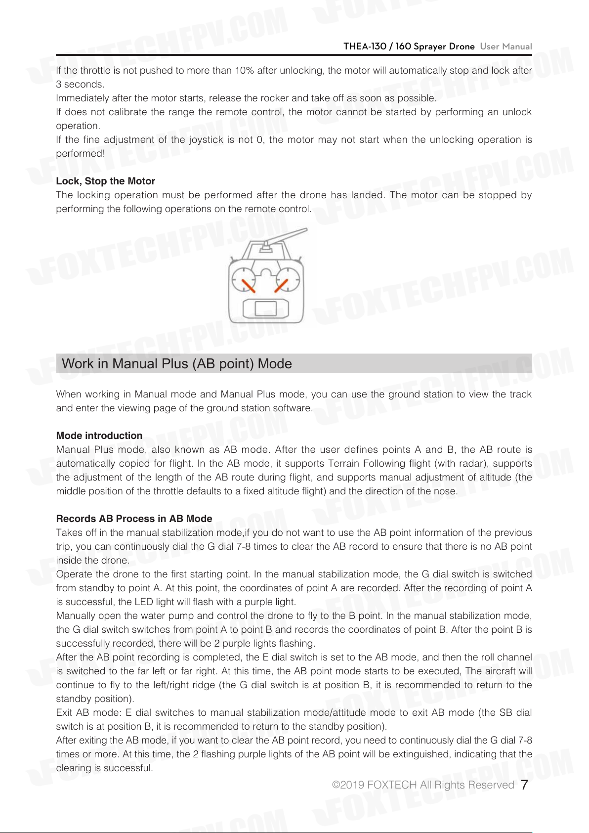
Unlock, Start the Motor
Before performing the unlocking operation, keep away from the
drone to avoid danger and injury. The motor can be started by
performing the following operations on the remote control.
Unlock
After unlocking, push the throttle stick above the middle position
and the drone can take off.
©
Push the throttle slowly.
2019 FOXTECH All Rights Reserved
6
Page 8
THEA-130 / 160 Sprayer Drone User Manual
If the throttle is not pushed to more than 10% after unlocking, the motor will automatically stop and lock after
3 seconds.
Immediately after the motor starts, release the rocker and take off as soon as possible.
If does not calibrate the range the remote control, the motor cannot be started by performing an unlock
operation.
If the fine adjustment of the joystick is not 0, the motor may not start when the unlocking operation is
performed!
Lock, Stop the Motor
The locking operation must be performed after the drone has landed. The motor can be stopped by
performing the following operations on the remote control.
Lock
Work in Manual Plus (AB point) Mode
When working in Manual mode and Manual Plus mode, you can use the ground station to view the track
and enter the viewing page of the ground station software.
Mode introduction
Manual Plus mode, also known as AB mode. After the user defines points A and B, the AB route is
automatically copied for flight. In the AB mode, it supports Terrain Following flight (with radar), supports
the adjustment of the length of the AB route during flight, and supports manual adjustment of altitude (the
middle position of the throttle defaults to a fixed altitude flight) and the direction of the nose.
Records AB Process in AB Mode
Takes off in the manual stabilization mode,if you do not want to use the AB point information of the previous
trip, you can continuously dial the G dial 7-8 times to clear the AB record to ensure that there is no AB point
inside the drone.
Operate the drone to the first starting point. In the manual stabilization mode, the G dial switch is switched
from standby to point A. At this point, the coordinates of point A are recorded. After the recording of point A
is successful, the LED light will flash with a purple light.
Manually open the water pump and control the drone to fly to the B point. In the manual stabilization mode,
the G dial switch switches from point A to point B and records the coordinates of point B. After the point B is
successfully recorded, there will be 2 purple lights flashing.
After the AB point recording is completed, the E dial switch is set to the AB mode, and then the roll channel
is switched to the far left or far right. At this time, the AB point mode starts to be executed, The aircraft will
continue to fly to the left/right ridge (the G dial switch is at position B, it is recommended to return to the
standby position).
Exit AB mode: E dial switches to manual stabilization mode/attitude mode to exit AB mode (the SB dial
switch is at position B, it is recommended to return to the standby position).
After exiting the AB mode, if you want to clear the AB point record, you need to continuously dial the G dial 7-8
times or more. At this time, the 2 flashing purple lights of the AB point will be extinguished, indicating that the
clearing is successful.
©
2019 FOXTECH All Rights Reserved
7
Page 9
THEA-130 / 160 Sprayer Drone User Manual
Route Node
Route Spacing
Left Right
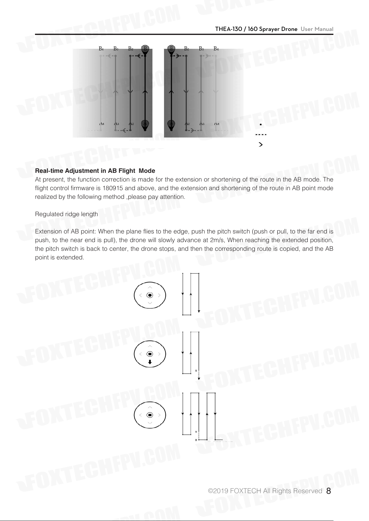
Real-time Adjustment in AB Flight Mode
At present, the function correction is made for the extension or shortening of the route in the AB mode. The
flight control firmware is 180915 and above, and the extension and shortening of the route in AB point mode
realized by the following method ,please pay attention.
Flying Direction
Regulated ridge length
Extension of AB point: When the plane flies to the edge, push the pitch switch (push or pull, to the far end is
push, to the near end is pull), the drone will slowly advance at 2m/s, When reaching the extended position,
the pitch switch is back to center, the drone stops, and then the corresponding route is copied, and the AB
point is extended.
©
2019 FOXTECH All Rights Reserved
8
Page 10
THEA-130 / 160 Sprayer Drone User Manual
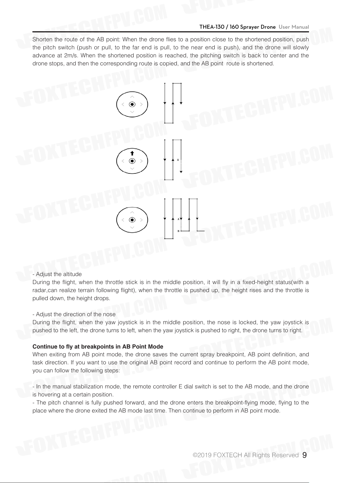
Shorten the route of the AB point: When the drone flies to a position close to the shortened position, push
the pitch switch (push or pull, to the far end is pull, to the near end is push), and the drone will slowly
advance at 2m/s. When the shortened position is reached, the pitching switch is back to center and the
drone stops, and then the corresponding route is copied, and the AB point route is shortened.
- Adjust the altitude
During the flight, when the throttle stick is in the middle position, it will fly in a fixed-height status(with a
radar,can realize terrain following flight), when the throttle is pushed up, the height rises and the throttle is
pulled down, the height drops.
- Adjust the direction of the nose
During the flight, when the yaw joystick is in the middle position, the nose is locked, the yaw joystick is
pushed to the left, the drone turns to left, when the yaw joystick is pushed to right, the drone turns to right.
Continue to fly at breakpoints in AB Point Mode
When exiting from AB point mode, the drone saves the current spray breakpoint, AB point definition, and
task direction. If you want to use the original AB point record and continue to perform the AB point mode,
you can follow the following steps:
- In the manual stabilization mode, the remote controller E dial switch is set to the AB mode, and the drone
is hovering at a certain position.
- The pitch channel is fully pushed forward, and the drone enters the breakpoint-flying mode, flying to the
place where the drone exited the AB mode last time. Then continue to perform in AB point mode.
©
2019 FOXTECH All Rights Reserved
9
Page 11
THEA-130 / 160 Sprayer Drone User Manual
Route node::::
Route spacing
Flying direction
Route breakpoint
Complete Route
Not executed route
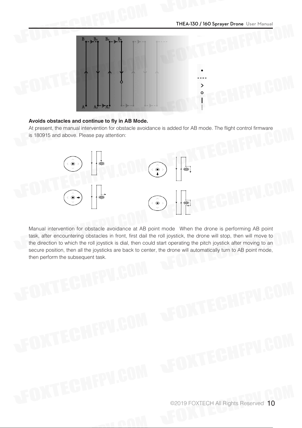
Avoids obstacles and continue to fly in AB Mode.
At present, the manual intervention for obstacle avoidance is added for AB mode. The flight control firmware
is 180915 and above. Please pay attention:
Manual intervention for obstacle avoidance at AB point mode: When the drone is performing AB point
task, after encountering obstacles in front, first dail the roll joystick, the drone will stop, then will move to
the direction to which the roll joystick is dial, then could start operating the pitch joystick after moving to an
secure position, then all the joysticks are back to center, the drone will automatically turn to AB point mode,
then perform the subsequent task.
©
2019 FOXTECH All Rights Reserved
10
Page 12
THEA-130 / 160 Sprayer Drone User Manual
Repair and Maintenance
Replace the Propeller
- Insert the propeller into the motor column (note the direction of the propeller).
- Turn the propeller, align the mounting holes, and tighten the four M3x6 screws.
Replace the Motor
- Place the motor on the lower cover of the motor base and align it with the mounting hole (note the direction
of the motor)
- Secure the motor and motor base lower cover with four M4X16 screws.
- Pass the motor wire through the hole in the lower cover of the motor base and connect it to the ESC.
Secure the motor cover and lower cover with four M3X10 screws.
Replace the ESC
- After the wire and signal wire at one end of the ESC pass through the arm, the wire is connected to
the distribution board, the signal line is connected to the flight controller, and the wire at the other end is
connected to the motor.
- In the motor check setting, check if the motor is turning correctly and the speed is the same as other
motors.
- The ESC is placed in the motor base, and the motor upper cover and lower cover are fixed with four
M3X10 screws.
Replace Nozzles
- Insert the nozzle into the nozzle fixed rod (Note: the connection part of nozzle and hose need to be
inserted into the fixing rod gap)
- Place the nozzle clamp into the nozzle and fix it with the M3 locknut and M3X14 screw.
- Prepare auxiliary tools such as pliers and pipe clamps, connect the hose from the pump to the nozzle.
:* Pass the hose through the pipe clamp and then onto the nozzle joint.
:* Use an auxiliary tool such as pliers to clamp the upper part of the pipe clamp to open it, move it to the
connection part of hose and joint, and then loosen it to clamp the connection part between the hose and
the joint.
Replace the Pump
-:Place the pump on the pump mounting plate (note: the arrow on the pump is facing up), align the
mounting holes, and secure with four M4X6 screws and four 4-flat washers.
-:Prepare auxiliary tools and pipe clamps such as pliers, and connect the nozzle and the hose exported
from the flowmeter to the water pump.
*:Pass the hose through the pipe clamp and connect it to the pump coupling.
: * Use an auxiliary tool such as pliers to clamp the upper part of the pipe clamp to open it, move it to the
connection part of hose and joint, and then loosen it to clamp the connection part between the hose and
the joint.
- Align the projections on the pump wire with the grooves on the pump connection and insert the pump
motor.
©
2019 FOXTECH All Rights Reserved
11
Page 13
THEA-130 / 160 Sprayer Drone User Manual
Cleaning After Use
The spray system needs to be cleaned after each use:
:Step1: Remove the filter from the nozzle and wash off the attachment.
:Step2: Wash the aircraft pesticide tank with soapy water.
:Step3: Clean the aircraft pesticide tank with clean water.
:Step4: Install the filter in the nozzle and then clean with water, and the degree of atomization of the nozzle
is used to judge whether it is cleaned.
©
2019 FOXTECH All Rights Reserved
12
Page 14
THEA-130 / 160 Sprayer Drone User Manual
System Introduction
System Characteristic
Main features:
· With the comprehensive flight status monitoring alarm function (including the state of power supply voltage,
state of inertial navigation, GPS, link-state, etc.) and perfect emergency protection mechanisms (including
return, hover, autonomous landing, etc.), and Paladin system can realize the control law of restructuring in
some failure cases of sensors or attitude algorithm, thus the maximum guarantee the safe operation of the
user's system;
· Provide highly integrated ground station software BY- GCS, which has the functions of flight data
monitoring, dashboard status display, abnormal status alarm, flying remote control, electronic map, route
planning, etc;
· The attitude algorithm of Paladin system adopts KALMAN filtering technology, which has high
measurement accuracy, and reduces the probability of attitude divergence, thus ensuring the reliability and
safety of the system work;
· Combined with the remote control device, the Paladin system can be controlled by the remote control
mode to control the operation, thus ensuring that multi-rotor UAV can step in and ensure flight safety during
take-off and landing.
· It provides a strong route planning capability and flexible task control function, and users can use ground
station software to make a variety of flight tasks conveniently service;
· The Paladin system integrates high precision inertial and satellite navigation sensors, and the sensor data
is covered by the pretreatment and the whole temperature range compensation and data fusion can obtain
flight attitude, position coordinate and working status in real time, and complete the high-precision attitude
and route control of the multi-rotor UAV platform;
· The Paladin system integrates dual degree CPU and sensor, which can automatically detect and switch
independently to ensure flight safety.
Navigation task:
· Offer up to 170 user routes, or 340 navigable points.
· Automatically generate return routes Protection configuration:
· Low voltage protection of battery;
· Exceed the maximum flying range protection (isolation regional security protection);
· Remote control protection;
· Radio interrupt protection;
· GPS fault protection;
Protection measures to switch to high maintenance mode;
· Flight overrun protection: when the aircraft pitch and roll attitude angle more than 60 °, the plane
automatically lock blade.
Remote control equipment:
· Compatible the commonly used remote control;
· Manually mode or autonomous control mode can be switched through the remote controller;
· Failsafe (protection when it’s out of control) status of the remote control can be monitored;
Airborne data record:
· Flight data is stored on dedicated storage devices for flight control;
©
2019 FOXTECH All Rights Reserved
13
Page 15

THEA-130 / 160 Sprayer Drone User Manual
Ground station software:
:
· Strong ability of route planning;
· A powerful digital map;
· A clear, intuitive flight instrument;
· Convenient operation and anti-error operation of key instructions;
· Integrated sensor calibration, protection configuration and other functions;
· The display, alarm and recording of telemetry data;
Communication interface:
:
· Physical interface: USB, digital radio;
Introduction to Flight Mode
Flight Control Mode
High maintenance mode.
Position maintenance mode.
Return mode .
Fully autonomous flight mode
(point mode formula).
AB point mode.
The Control Mode
Remote control.
Remote control.
Remote control.
Fully autonomous
can be divided
into 5 kinds of
flight modes:
1.autonomous takeoff
2.autonomous landing
3.waypoint flight
4. return
5. hover
Semi-autonomous
flight
Features
In the return of the remote rod, the
aircraft will maintain its own posture,
the position of the throttle can be
fixed, but the precise fixed point
suspension cannot be realized, and
manual correction is required.
When the satellite signal is good:
Hovering can be done with high
precision and the limit can be
achieved speed, but the RC remote
control aircraft still control, speed
can pass over ground station
settings.
Depends on the satellite, flew home
from the current point and hovered
over.
According to the ground station set
a good mission route, autonomous
flight, due to independent mode the
type depends on the satellite, so the
satellite should be located before
unlocking and taking off.
According to the set point A,
B, to achieve semi-autonomous
flight, this mode depends on the
satellite, so before the unlock and
take off the satellite to locate.
Remark
1. The route up to 170 article, that
way to do more 340.
2. The throttle can still control
height, throttle setting middle
will maintain the current height.
1. By the roll channel to provide
wrap instructions
2. By the pitch channel to provide
fine-tuning instructions.
3. The throttle can still control the
height and when it is set middle, it
will maintain the current height.
©
2019 FOXTECH All Rights Reserved
14
Page 16

THEA-130 / 160 Sprayer Drone User Manual
Installation and Connection
System Supporting List
Master control
High-precision and high-sensitivity GPS with positioning and orientation module using
external compass
Power conversion and monitoring module, allowing 6S~12S
Flight indicator
Data transmission radio on 2.4Ghz loaded on aerial vehicle, which is applicable for
ground station users
Data transmission radio on 2.4Ghz on the ground, which is applicable for ground station
users
Ultrasonic sensor, which is used for imitate-terrain flight and fixing height at low attitude
Data transmission checkpoint based on Bluetooth, which is applicable for ground station
on mobile phone users
Water pump governor, which is suitable for agriculture and plant protection unmanned
aerial vehicle users
Level sensor, which is suitable for agriculture and plant protection unmanned aerial
vehicle users
Flight Controller System Connection Diagram
This is the schematic of flight controller and peripheral equipment during installation:you must pay attention
to the direction of interface and install the interface firmly to avoid virtual connection. Diagram 2.2 is the
schematic.
©
2019 FOXTECH All Rights Reserved
15
Page 17

THEA-130 / 160 Sprayer Drone User Manual
Power System Description
Power supply range of Version 2 flight controller power module: DC 24V(6S)~50V(12S);
Power supply range of RTK base station: DC 24V (6S)~50V(12S)
Power supply range of RTK board: DC 12V (3S)~50V(12S)
Power supply range of water pump module: Input DC 24V (6S), Output DC 12V
Interface Denition
The panel layout of Paladin interface is as the picture shows.
©
2019 FOXTECH All Rights Reserved
16
Page 18

Interface definition picture on the front panel
Chart 2.1 interface board description
THEA-130 / 160 Sprayer Drone User Manual
Name
BY-RTK
LEVEL1
LEVEL2
RADAR
RADIO
LED
POWER
Use Instructions
Difference airborne terminal.
Contactless level gauge.
Reserved
Radar
Data transmission radio
External indicator.
Power interface.
Remarks
It should be pasted at the bottom of
medicine box with free nail glue.
There should be nothing blocked in the
range of 15 below the radar, and it needs
to be far away from the satellite navigation
module.
It needs to be far away from the satellite
navigation module.
If the external indicator is accessed,
indicators on motherboard of the flight
controller won’t work.
Input: 6S~12S, Output: DC 5V
©
2019 FOXTECH All Rights Reserved
17
Page 19

Interface definition picture on the back panel.
THEA-130 / 160 Sprayer Drone User Manual
Interface name
S.BUS
CH1~CH8
PUMP/NOZ
BUP-POW
Use instructions
Receiver interface.
Output Port of motor signal.
Pump/Centrifugal nozzle
signal port.
Backup power
Status Indicator Description
Here is Paladin’s status indicator,
Remarks
CH1~CH8 correspond to NO.1~8 motor. The signal
line splits into two, the shorter part links motors with
odd numbers and the longer part links motors with
even numbers.
The longer wire links the pump and the shorter links
the centrifugal nozzle.
©
2019 FOXTECH All Rights Reserved
18
Page 20

THEA-130 / 160 Sprayer Drone User Manual
Number
1
2
3
4
5
6
7
8
9
10
Status of RGB
Light is not on.
Lights of all colors are always on, and
it cannot connect with the ground
station.
The red light and the white light flash
alternately.
The red light, the yellow light, the
blue light and the green light flash
alternately. (in low brightness)
The red light, the blue light and the
green light flash alternately.
Only the yellow light flashes once.
Only the yellow light flashes twice.
Only the fuchsia light flashes once.
Only the fuchsia light flashes twice.
The fuchsia light flashes quickly.
Malfunction status
It’s crashed.
The flight controller
is initializing.
The equipment is
not calibrated.
The equipment is being
calibrated or tested.
Remote control failure.
Low power.
Magnetic compass failure.
Accelerometer failure.
Other failure before unlocking.
Instructions
Line fault or light fault
Remote control, compass and
accelerometer.
Motor test or ESC test
The gyro is not working properly.
11
12
13
14
15
16
17
The red light is always on.
The red light and the yellow light flash
alternately.
Only the blue light flashes once.
The blue light is always on.
Only the green light flashes once.
The green light is always on.
The green light flashes quickly.
The log storage evice failure.
GPS failure.
Cannot find GPS and
being locked.
Cannot find GPS and
being unlocked.
Can find GPS and
being locked.
Can find GPS, and
being unlocked.
GPS is working with
high precision.
If the blue light is on, it means
that there is no problem with the
equipment.
If the green light is on, it means
that there is no problem with the
equipment.
Paladin has three kinds of working status: one is the normal status, one is the calibration status and
the other is the protect status. Among them, the calibration status and the protect status mean that
the equipment is not working properly, you must pay attention to it!
©
2019 FOXTECH All Rights Reserved
19
Page 21

THEA-130 / 160 Sprayer Drone User Manual
Remote Control Equipment
Receiver
Paladin System could communicate with the receiver (like Futaba) which supports S.BUS through S.BUS
protocol. If S.BUS function doesn’t supported by the remote control, an optional PPM encoder is required.
The definition of each channel is shown in Table 3.1. The frequency should be adjusted before the use of
receiver. For detailed operation, please refer to the corresponding remote control manual.
Table 3.1 Definition of RCreceiver channel(take Japanese hand as example)
Receiver channel
number
1
2
3
4
5
6
7
8
Definition
Rollover
Tilt
Accelerator
Course
Flight mode.
Task load switch.
RTL Return and land.
Add breakpoint.
Remarks
For channel 5, except the flight mode, when rapid
repeated dial more than 6 times, flight control will
enter the magnetic compass calibration state. So do
not quickly and repeatedly dial channel 5 when not
necessary.
Two switches—Triggered in high level.
Return—Triggered in high level.
Two switches—Triggered by dial back and forth
once in auto/AB point mode.
The RC remote control's channel definition should be configured according to Table 3.1.
Remote Control Conguration
FUTABA remote controller is recommended for flight control operations (The remote requires at least 8
channels to achieve basic flight control functions). Specific remote control settings include the
following steps (take FUTABA 14SG, receiver R7008SB for example):
1. Double-click the LNK button to enter LINKAGRE MENU;
2. Enter the MODE SEL directory;
3. Choose NEW. Long press RTN to create a new control model(Fixed wing or quadrotor);
4. Click RTN twice to confirm;
5. If the remote accelerator is in the middle, please turn the ON of THR POS to OFF in the WARNING menu;
6. Enter the REVERSE menu, turn Channel 3 and Channel 6 NORM to REV;
©
2019 FOXTECH All Rights Reserved
20
Page 22

THEA-130 / 160 Sprayer Drone User Manual
7. Enter the FUNCTION menu, set AIL, ELE, THR, ROU to J1, J3, J2, J4 (Japanese Hand). Set AIL, ELE,
THR, ROU to J1, J2, J3, J4 (American Hand).Please map Channel 5 to 9 to the appropriate switch or knob.
The recommended settings are as follows: Channel 5 mapping is SE, Channel 6 mapping is SG, Channel
7 mapping is SC, Channel 8 mapping is SD, and Channel 9 mapping is SB. So far the basic settings of the
remote control are completed.
After configuring, please connect Paladin for verification. In manual (fixed high / fixed point) state,
the remote can control the motor. (without propeller).
Unlocking and Locking for Flight Control
The aircraft can take off only after unlocking (take Japanese Hand as example).
Unlockable mode: Altitude Hold / GNSS Assist / Position Hold Mode
Lockable mode: Altitude Hold / GNSS Assist / Position Hold Mode
Waysto Unlock:
· Unlock requirements:
1) Altitude Hold Mode: available after self-test passed;
2) GNSS Assist/Position Hold Mode: available after positioned by satellite and indicator flashes green light;
·Unlock action: Maximum tilting degree with lowest accelerator degree, push the course-control stick to
the far right and the rolling-control stick to the far left. Indicator light changes from blinking to steady means
unlock successful, as shown in figure 3.3a
Waysto Lock:
· To lock immediately, maximum tilting degree while with lowest accelerator degree, push the course-control
stick to the far left and the rolling-control stick to the far right.
· If the light starts flashing, the lock is successful.
©
2019 FOXTECH All Rights Reserved
21
Page 23

THEA-130 / 160 Sprayer Drone User Manual
ESC Calibration (Electronic Speed Controller)
The purpose of ESC calibration is to match the PWM value output by the flight control with the range of
PWM values that the ESC can receive.
The Paladin system provides two ESC calibration methods(take HOBBYWING ESC for example):
·General steps of ESC calibration(ESC signal line disconnected to flight control):
a. Connect a single ESC signal line to the receiver Channel 3(Accelerator Channel);
b. Power on the remote control, push the accelerator to the highest position, power on the ESC, hear "Di -
Di" twice, pull the accelerator to the lowest position, hear "Di - Di - Di" three times, then push the
accelerator, motor rotates, calibration completed;.
c. Repeat the above steps for other ESC calibration;
· Flight control ESC calibration steps(ESC signal lines and receivers have access to flight control):
d. Power on the remote control, push the accelerator to the highest position;
e. Power on the flight control, indicator lights flashing red and blue, flight control enter the ESC calibration
mode, turn off the power of flight control, the remote control maintains the highest position;
f. Re-power the flight control, turn on power system, when hear the ESC "beep - beep" sound, pull the
accelerator to the lowest position immediately, at this point will hear "Di - Di - Di" three times, then push the
accelerator again, motor rotates, calibration completed.
ESC calibration must be propeller-free, the audible tones of ESC calibration may be different by
different manufacturers, please refer to the manual of ESC .
©
2019 FOXTECH All Rights Reserved
22
Page 24

THEA-130 / 160 Sprayer Drone User Manual
Remote Control Protection
Protect Content
Paladin has perfect protection mechanism, the specific content and measures of protection are hown in
table 4.1
TABLE 4.1 Paladincontent and Measures of Protection
Protect Content
Low battery voltage.
Remote control signal lost.
Data link is interrupted.
GPS is abnormal.
No medicine.
Protect Measures
1. Return
2. Landing
3. Continue to perform the task.
1. Return
2. Landing
Return
1. Set High
2. Landing
1. Return
Description
-Protective measures: valid or
invalid.
-Protection mode optional.
-Protective measures: valid or
invalid.
-Protection mode optional.
Protective measures: valid or
invalid.
When GPS is abnormal, it will be
switched to fixed high mode. If high
modulus fails to switch, it will carry
out landing.
-Protective measures: valid or
invalid.
-Autonomous mode trigger
protection.
Regional restrictions.
Angle protection.
1. Not Open
2. Hovering
1. The maximum angle of flight
35 °.
2.Out of control protection
angle of 60 °.
©
Exceeded maximum radius: hover
Above maximum height: height
cannot climb, but can drop.
When the plane is in normal flight,
the angle will not exceed 35°;when
the pitch and roll angle more than
60 ° at the same time, fly machine
will turn off the motor output, lock
the paddle.
2019 FOXTECH All Rights Reserved
23
Page 25

THEA-130 / 160 Sprayer Drone User Manual
Return Logic
The trigger conditions of aircraft into the return status are: remote control channel 7 (return mode) to high,
the ground station control, the emergence of flight breakpoints, the phenomenon of runaway protection, etc.
The return process is: the aircraft climbed 2 meters in the current location (to ensure return safety, climbing
value can be set by the ground station), then fly to safety point (return back to the point if no automatic
mode has been taken off or return to nearest ascending point if there is a near standby point) and hovering
waiting for the operation, if the remote control signal is lost during the return process, the aircraft will hover
for 2 seconds to perform autonomous landing. The returning logic execution diagram is:
Remote Control Security
Remote control is the most direct means of control the aircraft, from a security point of view, the current
remote control for UAV plant protection operations are still irreplaceable. In order to ensure the safety of
UAV flight, taking into account the actual needs of large areas of independent spraying, PALADIN designed
a more complete remote control security strategy. The out-of-control protection action can be set by the
ground station software. It should be pointed out that the out-of-control protection setting of the remote
controller is only for the "fully autonomous mode"; the manual mode (constant height / positioning mode)
and the AB point mode are both open by default and cannot be closed, the remote control out of control
logic diagram (for details, please refer to "5.4.3 Security Settings"):
©
2019 FOXTECH All Rights Reserved
24
Page 26

THEA-130 / 160 Sprayer Drone User Manual
Data Link Loss of Control
Data link for aircraft and ground station connectivity, in order to improve ease of use, PALADIN the ground
station is set to asynchronous equipment required that the actual flight plane can observe the state of the
aircraft through the ground station, you can also disconnect the data link , only to observe the status of
aircraft and lights to determine the aircraft work. In order to prevent the instability of the digital link from
affecting the actual operation, the data link failsafe protection is set to be valid only in the fully autonomous
mode and the remote controller signal loss. The manual mode (fixed height, positioning) and the AB point
mode cannot be triggered, Autonomous mode remote control signal cannot be triggered normally, please
refer to the details according to "5.4.3 Security Settings."
Voltage Detection and Protection
PALADIN offers a voltage protection function based on a modifiable voltage value, that the user can correct
the voltage value of the flight control via the ground station (if the difference between the actual value and
the measured value can be used to correct the measured value), flight control detection monolithic voltage
and implement protection. The voltage fail-safe protection action can be set to "Off", "Return" or "Landing".
For details, please refer to "5.4.3 Security Settings".
Area Limited Protection
For details, refer to "5.4.3 Security Settings".
©
2019 FOXTECH All Rights Reserved
25
Page 27

THEA-130 / 160 Sprayer Drone User Manual
Ground Station Setting
Equipment Connection
1.Click “Not connected”:will pop up the following dialog box, select “Connect” to connect the drone,
“Connect handheld mapping device” to connect the handheld mapping device, “Connect RTK mapping
device” to connect RTK mapping device, “Connect RTK onboard” to connect RTK air unit.
2.Select the corresponding address based on the paired Bluetooth device.
©
2019 FOXTECH All Rights Reserved
26
Page 28

3.Waiting for the drone to be connected (voice prompt).
THEA-130 / 160 Sprayer Drone User Manual
Function Introduction
1.Main interface function.
©
2019 FOXTECH All Rights Reserved
27
Page 29

THEA-130 / 160 Sprayer Drone User Manual
2.Click “Display Seetings”, the user can select the parameter item you need (up to 6 items).
Click ”Setting”, then will pop up the dialog box.
Task Statistics: the cumulative number of working acres(Mu) ,Dosage (L) and time.
©
2019 FOXTECH All Rights Reserved
28
Page 30

THEA-130 / 160 Sprayer Drone User Manual
Frame Type Setting:Select the drone type (it has been set at the factory, please do not change it:
Motor test: Input duration (recommended 3s-5s), throttle (recommended 10%-15%), then according to
the diagram, check whether the propellers of the multi-rotor motors are normal (please test away from the
crowd to prevent accidents).
Remote Control Calibration
Check if the remote control joystick is in the position shown below, check the status of each channel in turn
(do not check multiple channels at the same time). If the position of the remote control joystick develop
offsets, please click the “remote control” button, then successively dial the channels of the remote control in
the maximum to the minimum range.
Please click” SAVE MODE” after modifying the fifth channel mode.
©
2019 FOXTECH All Rights Reserved
29
Page 31

THEA-130 / 160 Sprayer Drone User Manual
Calibration Setting
Calibrate accelerometer, horizontal calibration, dynamic balance correction.
3.Control Sensitivity Setting
©
2019 FOXTECH All Rights Reserved
30
Page 32

4.Safety Setting
THEA-130 / 160 Sprayer Drone User Manual
5.Agriculture Plant Protection Setting:
©
2019 FOXTECH All Rights Reserved
31
Page 33

6.System Setting(including system version etc.)
THEA-130 / 160 Sprayer Drone User Manual
Route Planning
1.Click :enter the route planning interface.
©
2019 FOXTECH All Rights Reserved
32
Page 34

THEA-130 / 160 Sprayer Drone User Manual
2.Click :Enter the mark mode, then select 1. work (working area), select the mark mode on the right
side, from top to bottom there are 3 modes: the mobile phone GPS positioning mark, mobile map manual
mark, aircraft GPS mark. Click the , start to mark. Use green lines and green markers as the edge
of the work area in the map. (at least three points form an area).
3.Mark the obstacle area in the work zone. Click :enter the marker mode, then select 2 Obstacle
obstacle area select to create new obstacle area (multiple obstacle areas can be created), select the mark
mode on the right side, from top to bottom there are 3 modes: the mobile phone GPS positioning mark,
mobile map manual mark, aircraft GPS mark. Click the start to mark, the red line and blue icons in the
map represent the obstacle area:at least three points form an area).
©
2019 FOXTECH All Rights Reserved
33
Page 35

THEA-130 / 160 Sprayer Drone User Manual
4.Click the on the left:to generate the route:the top parameters can be edited separately. From left
to right: the route interval, flight speed, start position of the route, route angle, obstacle avoidance scheme,
overall retraction of the work area (m), Expansion of obstacle area (m).
©
2019 FOXTECH All Rights Reserved
34
Page 36

THEA-130 / 160 Sprayer Drone User Manual
5. After the route planning is completed, click on the left side, upload the route to the aircraft.
6.After the upload is completed, you need to click :to download the route and ensure that the route is
transmitted to the aircraft accurately.
©
2019 FOXTECH All Rights Reserved
35
Page 37

THEA-130 / 160 Sprayer Drone User Manual
Ready to Take Off
1.Click to exit the route editing interface.
2.Click , the aircraft takes off automatically, the height is 2m.
3.Click , the aircraft enters the autonomous operation mode and will fly following the route that has
already been uploaded.
4.After the flight is completed, the aircraft will return to home automatically and hover:or click to
control the aircraft to return according to the actual situation.
©
2019 FOXTECH All Rights Reserved
36
Page 38

RTK Use Instructions
THEA-130 / 160 Sprayer Drone User Manual
©
2019 FOXTECH All Rights Reserved
37
Page 39

THEA-130 / 160 Sprayer Drone User Manual
©
2019 FOXTECH All Rights Reserved
38
Page 40

THEA-130 / 160 Sprayer Drone User Manual
Software terminal connection method
RTK work flow
Turn on your mobile phone Bluetooth:then match the devices with the default password 1234.
1. First work:
Connect your mobile phone and the base station:and save the position of the base station.
·Purpose of saving the position of the base station: In order to fix the position of the base station when
working in the same area the next time. It can ensure accuracy of navigation if the base station is in the
same position(less than 5m) in the same region using the same route. If the situation doesn’t match, the
accuracy of navigation will be reduced, but it won’t affect the work. So you should select whether it needs to
fix the position of the base station, if not, you don’t need to save the position.
Specific methods of operation:
Switch the “route planning” interface on your mobile phone, and click “connect RTK base station”
·When prompted “connection XXX success”, it means that Bluetooth connection is successful.
When prompted “connection XXX failed”, it means that Bluetooth connection is failed.
·When prompted “receive RTK base station data successfully”, it means that the data we received is right.
·If it’s prompted “receiving data” for a long time, it means that Bluetooth connection is successful, but it
hasn’t received effective data, please wait.
If RTK base station data is right, the position of RTK base station will be displayed on map at real time (blue
point).
If you click the , as shown below will appear:
Select the type of area point to be added.
RTK Base station position.
Cancel Mapping Model In the Field
Click “mapping model in the field”, then click , the position of RTK base station will be displayed on
map . at the same time, the ground station will save the position as file (in Boying-GCS/RTK/ , the suffix
name is .rtkbase). You can mark many points on map, every point you mark will be saved as file separately.
After marking points of position of the base station, click “disconnect RTK base station” in the upper right
corner.
©
2019 FOXTECH All Rights Reserved
39
Page 41

THEA-130 / 160 Sprayer Drone User Manual
Concise Operation Process
1) check power cable and cable between peripherals and flight control;
2) launch ground station, and launch BY-GCS ground station;
3) switch on RC remote control equipment;
4) switch on the aircraft system and connect to the ground station;
5) calibrate the remote control, if it has been calibrated, skip;
6) calibrate the electronic governor(Do not install propellers.), if it has been calibrated, skip;
7) start the function of motor test on the ground station, and make sure the whirling and the serial number of
motors match;
8) calibrate the accelerometer, if it has been calibrated, skip;
9) calibrate the magnetic compass, if it has been calibrated, skip;
10) set flight model;
11) set protection of being out of control;
12) check if there is any warning from the ground station, analyze the reasons and solve it;
13) check if key data is normal such as attitude data, course data and GPS data, and move the aircraft to
observe whether change of data is normal;
14) check installation of external GPS and compass;
15) check installation direction of the flight control and damping;
16) check whirling direction of motors and propellers and check if they are installed firmly;
17) toggle switches of flight models and observe whether the displayed area in flight model on the ground
station switches normally;
18) set route tasks and upload, then download them and make sure the route has been planned right; If you
have any question, don’t force it to fly, please contact the technician.
Only when the position has been decided by GPS can you unlock it in the fixed-point model.
©
2019 FOXTECH All Rights Reserved
40
Page 42

THEA-130 / 160 Sprayer Drone User Manual
Precautions
Due to safety concerns, here is what you should pay attention to before using:
Environmental factor precautions:
1) Try to be familiar with the flight environment and be far away from the obstacle and the crowd when flying
2) Don’t fly when in low spirits.
3) Don’t fly after drinking wine or taking psychotropic drugs to avoid causing accidents because of human
factors.
4) Don’t fly in thunderstorm or windy weather to avoid the damage of equipment and the danger of flying.
5) If you need to use it in glare, please use sunglasses.
6) Be far away from high-temperature heat source to avoid damage to the electronics.
7) Beginner should be taught by experienced pilots before using.
8) You should prepare necessary tools before using, such as wrenches, screwdrivers, spare propellers,
telescopes, walkie-talkies, sunglasses, first aid kit and so on.
9) Don’t overload, or it will cause damage to the aircraft structure and fly dangers.
10) Be far away from propellers rotating at high speed,
11) Check every device before flying, if the key devices don’t work normally, and don’t force it to fly, or it will
cause accidents.
Equipment factors precautions:
1) We suggest that you had better debug the aircraft when propellers are not installed, check if the remote
control and motors work normally, and then install propellers if everything is ok.
2) Keep the accelerator the lowest before flying.
3) Check if there is any interference on the same frequency among devices.
4) The 2.4G antenna has weak ability of avoidance, please keep a good visibility between antenna on the
aircraft and on the ground station while flying. Put the ground station at a height and keep the antenna up
when using, and keep the antenna on the aircraft down as possible so that it can increase the distance of
transmission.
5) Check if every device works normally.
6) Make sure the life time of your battery matches your needs, such as the battery in your remote control
and your aircraft.
7) Check if whirling direction of propellers is right.
8) Follow the instructions strictly.
©
2019 FOXTECH All Rights Reserved
41
Page 43

THEA-130 / 160 Sprayer Drone User Manual
Failure Analysis
1) Cannot unlock
a. The accelerator is not set the lowest.
b. The tilt angle of the aircraft is too large.
c. The signal line of the receiver doesn’t connect well, or it has connected to the wrong interface.
d. Observe the warning from the ground station and check if sensors and the remote control have been
calibrated.
2) When do you need to calibrate the magnetic compass
a. If you have moved or disassemble the flight control or GPS,
or it’s far away from the region where you calibrated last time,
or the magnetic field has changed a lot.
b. You can check if the data from the magnetic compass is right, for example, if the aircraft turns around,
the course will change 360 degrees, and observe if the course data from the ground station is with the
actual match.
3) Rotating speed of motors doesn’t match when you increase the throttle.
a. If the throttle is too low, rotating speed of motors doesn’t match, but it matches after you increase the
throttle, it’s a normal phenomenon. If motors still don’t match after you increase the throttle, you need to
calibrate the ESC again.
4) rotate after taking off or flip
a. Check if propellers are installed correctly.
b. Check if the whirling direction of motors is right.
c. Check if the dynamic equilibrium of the aircraft is well. You can reference the “troubleshooting center” on
our official website to get more failure analysis, or you can contact us for technical support, we will answer
timely.
©
2019 FOXTECH All Rights Reserved
42
Page 44

THEA-130 / 160 Sprayer Drone User Manual
After-sales Service
Warranty regulation
·If the malfunction is caused by products quality, BOYING will offer limited quality assurance in the circuit
part.
·Since the date of purchase, six months is the shelf life based on the proof of purchase.
·If it’s within the warranty period and within the warranty, BOYING will offer free replacement or maintenance
service.
Not covered by the warranty
·Not follow instructions provided by BOYING when installing or operating.
· Performance problems caused by man-made improper operation or chemical agents.
·Performance problems caused by the unofficial part.
· Electronic equipment performance problems caused by water.
·Performance problems caused by private modification.
·Performance problems caused by electronic interference.
·Performance problems caused by using poor quality power or using nonstandard input voltage.
· Damage caused by human factors (such as handling, operating error, collision and so on).
·Damage caused by irresistible factors outside world (such as earthquake, typhoon, thunderstorm, fire and
so on).
©
2019 FOXTECH All Rights Reserved
43
Page 45

THEA-130 / 160 Sprayer Drone User Manual
Installation of Ground Station and Drivers
Installation
Operating environment: WIN2000, WINXP, WIN Vista, WIN7, WIN8, WIN10
First, if you want to install it in Win10 system, it needs digital certificate authentication; the specific operation
is as follows:
1) Click “settings” ”update and safety”
2) Click ”recover”->” advanced startup” -> ”restart immediately”
3) After restart, click “troubleshooting”-> ->”advanced options”->”startup settings”->”restart” follow the
prompts to enter 7 to forbid drivers to force signatures Then, install the ground station software:
1) Click “ByAero.exe”
2) Choose the installation path
3) Follow the prompts
4) Finish
Finally, if you need to connect the flight control to the ground station using USB cable, please make sure
that you have chosen the right driver, as shown below:
Install data transmission driver:
The first method: If your computer is in a networked state, access the data transmission radio, drivers will be
loaded automatically.
The second method: If your computer hasn’t link to the network, unzip “BOYING data transmission drivers”
to the root directory of C, then access the data transmission devices on the ground station, it will prompt
that it could not find drivers.
Specific steps of loading drivers are as shown below:
a. Right-click “my computer”->”management”->”devices management”->”port”
b. Choose the driver with yellow exclamation point, right-click “update drivers”->”browse the computer…”
choose the folder where to unzip the driver, click “next”. If installation fails, repeat it twice or more.
©
2019 FOXTECH All Rights Reserved
44
Page 46

THEA-130 / 160 Sprayer Drone User Manual
This content is subject to change.
Download the latest version from
https://www.foxtechfpv.com/thea-130-agriculture-spraying-drone.html
https://www.foxtechfpv.com/thea-160-agriculture-sprayer.html
For everyday updates, please follow
Foxtech Facebook page: Foxtechhobby
YouTube Channel: Foxtech
©
2019 FOXTECH All Rights Reserved
45
 Loading...