

Page 1

S1+
WIRELESS HD VIDEO TRA N S MISSION
INTRODUCTION /INSTRUCTION /INSTALLATION GUIDE
Page 2

Content
1、Disclaimer----------------------------------------------------------------------1
2、Announcement ----------------------------------------------------------------1
2.1 Installation Warning----------------------------------------------------------1
2.2 Usages warning ---------------------------------------------------------------1
3、Product profile-----------------------------------------------------------------2
4、Description ------------------------------------------------------------------2
4.1 Transmitter --------------------------------------------------------------------2
4.2 Receiver -----------------------------------------------------------------------3
4.3 Accessory----------------------------------------------------------------------3
5、Wiring installment------------------------------------------------------------4
5.1 Carrier connection diagram-------------------------------------------------4
5.2 Receiver connection diagram-----------------------------------------------5
6、Usages -------------------------------------------------------------------------5
6.1 Channel settings --------------------------------------------------------------5
6.2 Video record ------------------------------------------------------------------6
7、Working indicator-------------------------------------------------------------6
7.1 Transmitter indicator----------------------------------------------------------6
7.2 Receiver indicator-------------------------------------------------------------6
8、Specification parameter-------------------------------------------------------7
8.1 Video transmitter specification-----------------------------------------------7
8.2 Video receiver specification--------------------------------------------------7
9、FAQ (frequently asked question)-----------------------------------------9
Page 3

Disclaimer
Thanks f o r purchasing S1+.Please ensure thatS 1 + isusedinaccordance with local
lawsa n d regulations. Please read thisdisclaimer carefully before using. O n c e used, its h a l l be
considered a s a n endorsement a n d acceptance ofthewhole content ofthis statement. Please
strictly follow theinstallation s t e p s intheinstructions tooperate a n d usetheproduct. Fora n y
result orlosscaused byimproper use,installation, modification,etc., FOXTECH HOBBY
CO., LTD a n d its affiliated companies will notholda n y legal liability.
T h e copyright ofthis usermanual belongs toFOXTECH HOBBY CO., LTD. A l l rights
reserved. Reproduction s h a l l notbem a d e ina n y f o r m without permission.
Announcement
S 1 +
isa w i r e l e s s v i d e o transmission equipment, pleasep a y m o r e attention totheannouncement to
prevent damagetoterminal equipment andpersonal s a f e t y duetoimproper operation o r usage.
1.Please usecorresponding frequency o f
complywith local r a d i o l a w s andregulations.
2.For first usage, pleasem a k e s u r e thatthetransmitter andreceiver areconnected correctly andthe
antenna isinstalled correctly.
S1+
products inaccordance with local r a d i o regulations and
1、 Installation W a r n i n g
1.Before setting upanelectric circuit, theusershould install theantenna andm a k e s u r e thatthe
interface istightened. Otherwise, itw i l l damagetothecircuit.
2.Pleasem a k e s u r e thetransmitter andreceiver supply thevoltage within theprescribed voltage r a n g e .
Otherwise, itw i l l damage tothecircuit.
3.Beabletokeep antenna o f transmitter downvertically andwithout anyobstacles toprevent
shortening communication distance because o f blocking.
4.T h e antenna o f receiver should beabletokeep away from l a r g e m e t a l p a r t s .
5.Please bes u r e tousea specified typeo f antenna toensure thatthefrequency, impedance ando t h e r
parameters match.
6.Please payattention tokeeping theproper distance between theelectronic equipment tominimize
theelectromagnetic interference.
2、 Usage warning
第 1 页
Page 4
1.Please make sure that all connecting wires are fastened and connected correctly.
Video transmission and data transmission;
Transmission distance reaches 5~10Km;
Input and output by HDMI and supporting 1080p60fps and downward compatible;
Latency is low to 200ms;
The frequency is 1430MHz-1440MHz;
Passed SRRC.
2.There is no entry into any foreign body (e.g. liquid,sand,etc.)
3. S1+ needs to 40 seconds to turn on, after that, can transfer video.
4.Please ensure that there is no interference in the surrounding environment with the
same frequency and high power wireless transmission equipment, otherwise the receiver
may not receive the video normally.
5.If the signal of the ground is poor, try to change the inclination of receiver’s antenna.
6.Using HDMI cable, LCD display and other accessories, select a better EMC shielding
performance of the product as far as possible.
Product profile
S1+ consists of transmitter and receiver. It can support video transmission and data transmission.
Adopted by H.265/H.264 video decode, OFDM modulation technique, S1+ provides lower latency and
smaller bit rate video. It is suitable for UAV and other applications which need to have two functions:
video transmission and data transmission.
S1+ Technological advantage:
Description
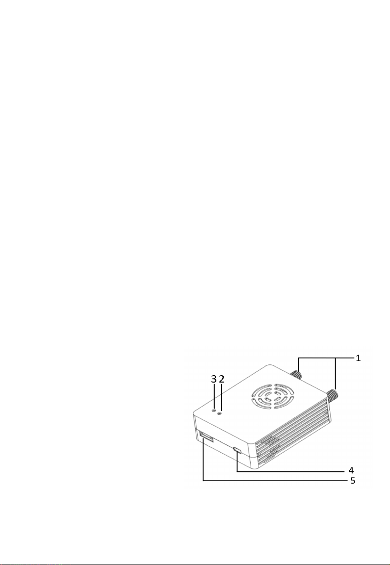
Transmitter
1、Antenna interface;
2、Connection status indicator;
3、Power indicator;
4、HDMI interface(type D);
5、Power and Data(UART TTL) interface.
第 2页
Page 5

Receiver
1、Power source/data transmission interface 2、HDMI video output interface
3、Power source indicator 4、Connection status indicator
5、Recording status indicator 6.7、Antenna interface
8、REC start recording /stop recording button 9、USB interface
Antenna accessory
Power source/data transmitter cable ×2 Antenna ×2
HDMI cable D to D ×1
Whip antenna ×2
第 3页
Page 6
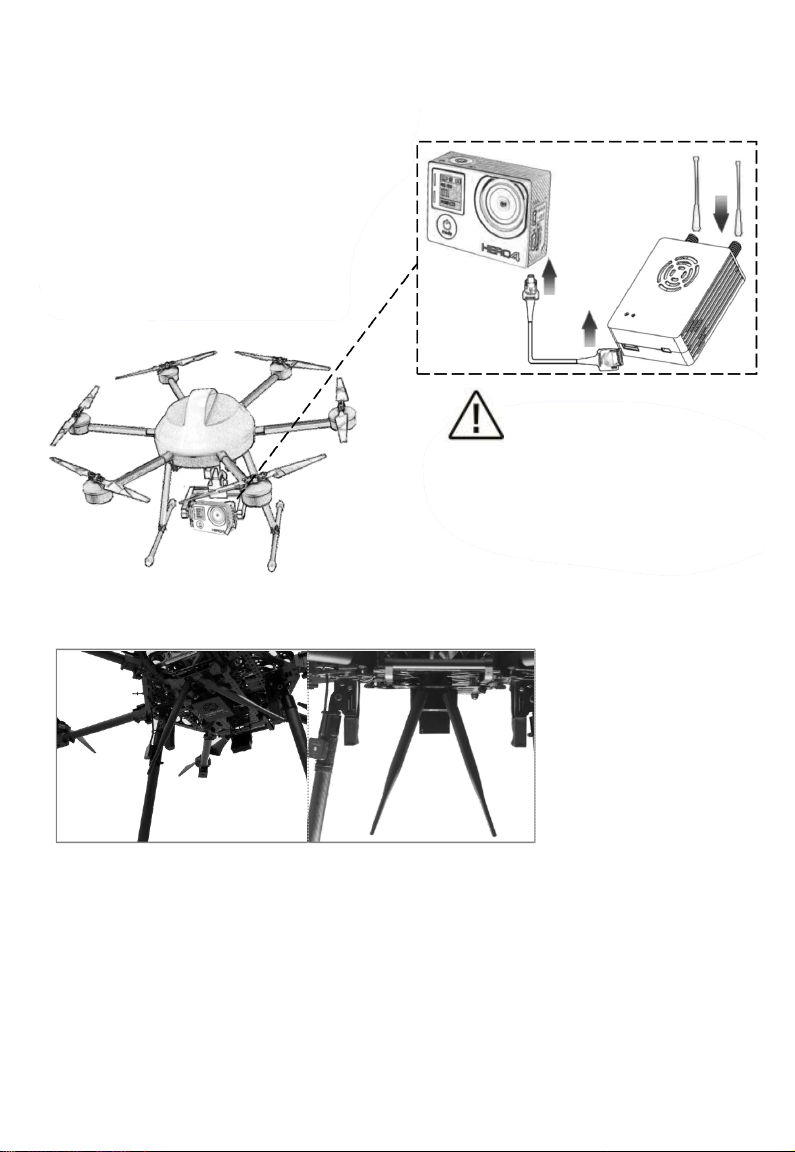
Installation and wiring
Take Muti-rotor UAV for an example:
Connection diagram:
Fix the transmitter on the suitable
Station of drone(by 3M plug or strap),
and then install antenna with vertical down.
Next, connect camera and transmitter
with HDMI cable (or with CVBS cable),
and then connect to power.
Examples:
Attention:
Please ensure to install the transmitter
antenna and fasten it before POWER ON.
Otherwise, it will damage the transmitter.
第 4页
Page 7

Receiver connection diagram::
Connect the HDMI of receiver to LCD display.
And connect the antenna ,fasten it.
Installation notes
1.Keep the antenna away from metal equipment of drone, and the antenna should have wide space
within 20cm to other objects to ensure efficient transmission;
2.Make a proper planning about frequency of all wireless equipment on UAV. Otherwise it will cause
the equipment to be unable to use normally .
:
Usage
S1+ wireless HD video/data includes transmitter and receiver.
Connect an appropriate antenna to the transmitter and receiver.
Connect and /or apply a suitable power source to the unit.
Connect HDMI cable to LCD display.
After power on, waiting 15 seconds, the connection status indicator lights. The transmitter and
receiver connect successful.
Within 30 seconds, receiver receives the video signal from transmitter.
Video record
Wireless HD video receiver support video recording. The steps are as follows:
1.Insert USB device, HDMI of receiver output “USB device is inserted” .
(Receiver)
第 5页
Page 8

2.Start video recording by short press receiver “SW”, and the OSD on the display indicates:
“Recording XX:XX:XX”(XX represent the hour, minute and second of recorded video)
3.To stop recording, please press “SW” again. After finishing recording, video is automatically saved
to USB storage device in “mp4_record”.
4.When USB device is pulled out, OSD on the display indicates “USB Device Removed”.
第 6页
Page 9
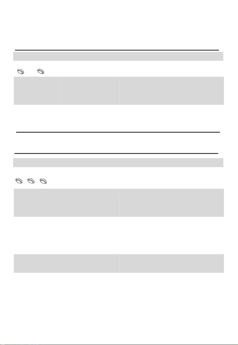
LED indicator
Transmitter status Description
Product Video transmitter
3 2
Red Power source of device works normally
3: Power source indicator
OFF
2: connection status
indicator
Green The receiver and transmitter connect successfully.
OFF Abnormal signal connection between receiver and
Receiver status Description
Product HD video transmission
3 4 5
Power
Connection
status indicator
Recording indicator
Red Power source of device works normally
OFF Device is not power on or device is abnormal after
Green The signal of receiver and transmitter successfully
OFF Abnormal signal connection between receiver and
Green Device is recording
OFF Device is not recording
3: Power ; 2: connection status indicator
Device is not power on or device is abnormal after
powering on(please contact FAE)
transmission
3: Power source indicator
4: Connection status indicator
5: Recording indicator
powering on(please contact after-sales)
connect.
transmission
第 7页
Page 10

Specification
Model Transmitter
Antenna interface 50Ω SMA Encoded/Decoded H.265/H.264
Modulation OFDM Resolution 1080p @60/50/30
Vedio input HDMI ( D ) Voltage DC 9~28V
Frequency
Bit rate 3~12Mbps
Transmitting
power
Bandwidth 10MHz
Latency 200ms
Dimension 70*56*23mm
Weight 89g
Model Receiver
Antenna 50Ω SMA Encoded/Decoded H.265/H.264
Modulation
Format
Video Interface
Frequency
Voltage
Video Bit Rate
Bandwidth
Latency 200ms
Dimension 91*75*25mm
1430MHz-1444MHz
23~25dBm
OFDM
HDMI(A)
1430-1444MHz
DC 9~28V
3~12Mbps
10MHz
UART 3.3V TTL
UART Rate
115200
1 Start, 8 Data,
UART Format
1 Stop, No parity
checking
Transmission
5~10km
Distance
Power Consumption
Resolution
UART
UART Rate
UART Format
≤8W
1080p @60/50/30
3.3V TTL
115200
1 start、8data、
1 stop 、 No parity
checking
Transmission
5~10km
Distance
Power
≤8W
Consumption
Weight
141g
第 8页
Page 11

FAQ (frequently asked question)
Questions Possible reason Solution
Device can not power up, power
source indicator not light
Receiver
Indicator not light
Signal indicator not light,
receiver display output :
Transmitter Loss
Signal indicator always
on, receiver output : no
video input source
●Unturned transmitter ●Check that whether the transmitter is properly
●Abnormal signal
of transmitter
●Transmitter has no source
input
●HDMI connecting Video
source to transmitter is
disturbed
●The compatibility problem
of transmitter and video
source.
●Interface of power source is poor
contact
●Damaged cord ●Replace new power cord
installed and powered on
●Check that whether transmitter and the antenna
connect fastening, if applicable, test output
power of transmitter is normal or not.
●Please check the signal status of transmitter, check
HDMI interface again, at the moment, check the
camera.
●Replace HDMI connection between video source
and transmitter to the shielding
line.(recommended original accessories)
●First, close the transmitter and video
source, after confirming HDMI connection
is normal, open video source.
●Turn off power source, plug in to
the socket again, after
confirming, connect to power
source.
第 9页
Page 12

Data transmitting
is abnormal
●Default setting UART rate is 115200 (No
traffic control), 1 start,8data,1 stop,No
●Related configuration
parameters are incorrect
parity checking. Please configure to the
above parameters. If it is not convenient
to modify, please contact the
manufacturer.
●Interface connection error ●Check that wire connection is correct with
reference to the pin definition
Video can not be recorded
or recorded error
●USB storage device version ●Recommend USB3.0 to save video document
●Compatibility of software
on the computer
●Please play the recorded files by player of
windows
第 10页
 Loading...