

Page 1
www.chinowing.com
RB20
Signal Relay
V2.1
user manual
2019.1
Page 2

2
www.foxtechfpv.com
Content
isclaimer . .............................................................................................................. 3
D
Product Notes
Brief Introduction
Product List
Using Instructions
Ground Unit Diagram
Air Unit Diagram
RB20 Indicators
RB20 Connection Diagram
Parameter
Out-of-Control Protection Setting
. ..................................................................................................... 3
. ................................................................................................ 4
. ........................................................................................................... 4
................................................................................................. 5
.......................................................................................... 5
................................................................................................... 6
..................................................................................................... 8
. ............................................................................... 9
Configuration .................................................................................... 9
............................................................. 12
Firmware Upgrade
FAQ
. ....................................................................................................................... 14
. ............................................................................................ 12
Page 3

3
www . foxtechfpv.com
DDDiiisssccclllaaaiiimmmeeerrr
Thanks for purchasing the RB20 signal relay. Please use RB20 according to local
radio regulations. Please read this statement carefully before using it. Once used,
it is deemed to be an endorsement and acceptance of the entire contents of this
statement. Please strictly follow the instructions to install and use the product.
FOXTECH TRADE CO., LTD will not bear any legal responsibility for any consequences
and losses caused by improper use, installation, assembly and modification of
customers.
PPPrrroooddduuucccttt NNNooottteeesss
1. Input voltage of RB20 ground and air unit is DC7.4 - 12V(lipo 2s - 3s),please
strictly follow this parameter to power the module.
2. Be sure to install the antenna before powering up to avoid damage to the circuit.
3. Make sure that the antenna is free from obstructions in using process, and try to
keep away from large metal objects to avoid communication obstruction.
4. Do not disassemble or reassemble RB20 module, If you encounter problems that
cannot be solved during installation or use, please contact FOXTECH or your agent.
5. Keep the proper distance between the electronic devices during installation to
minimize electromagnetic interference between devices.
6. Make sure all connections are securely fastened and all parts are working properly
before use.
7. Please check the surrounding environment before use to ensure that there is no
interference from other 840MHZ-930MHZ equipment, otherwise the RB20 data
transmission may be seriously affected.
Page 4

4
www . foxtechfpv.com
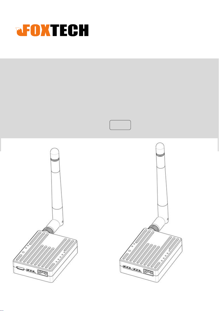
BBBrrriiieeefff IIInnntttrrroooddduuuccctttiiiooonnn
RB20 Signal Relay is designed to work with radio controller to achieve the long range
requirements. The RB20 ground unit could be connected to PC through a TTL-USB cable,
to realize data transmission between PC and RB20 air unit, also could realize parameter
tuning. The max communicate range is 30km.
PPP rrr ooo ddd uuu ccc ttt LLL iii sss ttt
Main Module
Ground Unit
Air unit
Page 5
5
www.foxtechfpv.com
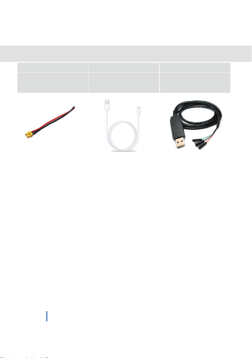
Accessories
Poweer cable x2
usb cable
Data cable
(DC:7.4-12V)
For grount unit parameter
tuning or serial connection
UUUsssiiinnnggg IIInnnssstttrrruuuccctttiiiooonnnsss
RB20 has 2 signal outputs:
S, so you need to buy a
receiver not support
GGGrrrooouuunnnddd UUUnnniiittt DDDiiiaaagggrrraaammm
S-BU
For air unit
parameter tuning
S-BUS
and Serial port.if your remote controller or
PWM
to
S-BUS
module.
Page 6

6
www.foxtechfpv.com
RC Receiver
Page 7

7
www.foxtechfpv.com
P
lease check the connection status by following step
s after the connection is
completed.(This step will have some differences because of different flight controls.)
1.
Open the
PC
recognized, the driver is installed correctly, and there is no yellow exclamation
mark.
Open the
2.
FC
ground station software,select the corresponding COM port, and connect to
the flight controller.
transmission link
is connected. If the connection fails, please check the following points.
device manager and you can see that the ground
T
he flight control is connected normally
,indicating that the RB20
unit
is correctly
digital
1.The baud rate of the flight controller is
2.Ensure that the
3.Use the
RB20
settings for
Ensure thatRXof FC to TX RB20,TX of FC to RX RB20.
4.
3. Open the
rc
setting interface of the ground station to check whether the remote
RB20
ground
parameter setting software to ensure that all parameter
RB20 air
and ground
unit
driver is installed successfully.
are consistent.
unit
same as
the baud rate of
control data is normal. If the remote control data changes normally
RB20
along
.
with the
joystick. The remote control link is connected. If the remote control connection fails,
please check if the “-, +, signal” of the S-BUS is reversed.
Page 8

8
www.foxtechfpv.com
RRRBBB222000 IIInnndddiiicccaaatttooorrrsss
①S-BUS data indicator L1
L1 flashs means that the remote control has data transmission, and no flashing means that the remote control has
no data transmission.
②Configuration mode indicator L2
L2 s
teady light-
③SET Button
Used to enter the configuration mode or set the runaway protection output value or upgrade firmware
④Data transmission indicator
RXD light is on-receiver has data reception; TXD light is on-receiver has data transmission.
⑤ Signal Strength
S1 S2 S3
middle-level
in
the configuration mode
- signal stregth indicator, all these three indicators are on- strongest signal quality; only
signal quality
; onlyS3on-general signal quality.
S2S3
.
on-
Page 9

9
www.foxtechfpv.com
RRRBBB222000 CCCooonnnnnneeeccctttiiiooonnn DDDiiiaaagggrrraaammm
Air Unit
Ground Unit
Power on the ground unit and air unit, if the light is illuminated as shown below, it
means the two modules are connected normally.
keeps on
keeps on
flashing
keeps on
keeps on
keeps on
Parameter Configuration
The parameters have been set at the factory and you should be able to use RB20 directly. In the following
situations, you may need to modify the RB20 parameters:
1.The flight control baud rate is inconsistent with the RB20 preset baud rate.
2.Multiple Rb20 occupy the same communication channel, causing communication blocking.
3.Have special communication bandwidth and communication power requirements.
Please follow the steps below to modify the parameters:
The parameter modification method of ground unit and air unit is basically the same, only the
connection cable is different.
1Press and hold the set button, then power up until the L2 light is on, release the button.
Page 10

10
www . foxtechfpv.com
2、According to Pic.1 and Pic.2,connect ground unit to PC or connect air unit to
PC. Data cable for air unit: white cable connect to TX, black cable-GND, green
cable-RX.
Pic.1 Air unit connected to Configuration Software
Pic.2 Ground unit connected to Configuration Software
Page 11

11
3、 Use the matching assistant software, select the corresponding port and
www . foxtechfpv.com
click the connection to read the parameters, as shown in the figure below.
4、If you want to modify the parameters, just change the corresponding value
in the software, click on the Write, and then Confirm, as shown below.
5、After the modification is completed, press the Set button again or power up
again to exit the configuration mode.
Note: 1. Please ensure that the parameters of the ground unit and air unit are exactly the same, otherwise
the two modules cannot communicate.
2. Communication bandwidth and communication power directly affect communication quality and
communication distanceIf you don’t understand its meaning, please do not modify these two parameter
values.
After entering the configuration mode to complete the parameter configuration, be sure to exit the
3.
configuration mode.
Page 12

12
www . foxtechfpv.com
RC Out-of-Control Protection Setting
If you need to set the using protection of the remote control, please follow the steps
below:
1. Write the runaway protection data
When the air end is properly connected to the ground end and there is remote control
data transmission, short press the set button of the air end (about 0.5S), the value of the
current remote controller can be stored as an out-of-control protection value on the air
end, and will not be lost after power failure. Please use the FC ground station or servo to
test whether the runaway protection data is successfully written.
2. Trigger out-of-control protection value
When the air unit does not receive the S-BUS data from the ground unit for 3s the air end
will always output the previously written out-of-control protection value until the S-BUS
data from the ground end is received.
3. Turn off out-of-control protection
When the air end is properly connected to the ground end and there is remote control
data transmission, press and hold the Set button(≥3S) on the air unit to turn off the
out-of-control protection. Please use the FC ground station or servo to test whether the
out-of-control protection is successfully turned off.
NNNooottteee:::
By default, the RB20 has no out-of-control protection value output.
While using RB20, please select the GCS Protection function, so when the aircraft does
not receive the S-BUS signal from the ground , the aircraft will automatically trigger and
return home.
Firmware Upgrade
1. Open Bootloader upgrade software
Page 13

13
www.foxtechfpv.com
2
. connect to USB port or TTL port through a USB cable or data cable,
hold the
the
number
et button
S
et
S
button
again until L1 and L2 are
at the same time, it
power on, then the L2 light is always on.Then press and hold
and
always ona
indicates that the upgrade mode
nd the software displays the port
is
entered.
Press and
3. Open the correct firmware you downloaded. If it is correct,
“
firmware file identification is completed.
”
will display
Page 14

14
www . foxtechfpv.com
. Click the Start button, until it prompts that the firmware writing operation
4
is completed, that means the upgrade is successful.
FFF AAA QQQ
1:receiver S-BUS has signal outputbut can not connect the serial port, or
transmission signal garbled.
Please check whether the baud rate of the serial port on the air unit and the
ground unit is the same; set the baud rate corresponding to the ground
station software.
2:Two or more devices have interference powered on at the same time.
The ID of each set must be different, and the channel should also be set
to a different value to avoid co-channel interference.
 Loading...