

Page 1
GAIA 160AG
Agricultural Spraying Drone
User Manual
V1.0
2019.04
Page 2
Contents
GAIA 160AG-Agricultural Spraying Drone User Manual
Specications
SetupandCalibration
BasicTheory
N3-AGIntroduction
N3-AG Parts
AgricultureManagementUnit(AMUII)Introduction
RemoteController
Installation
Overview
Start the Installation
SystemFunctions
Flight Modes
Operation Modes
Operation Resumption
Data Protection
Empty Tank Warning
Return to Home (RTH)
Attitude Control When One Motor Output Fails
Propulsion System Protection
Altitude Stabilization System
Radar Module
DJIMGApp
Linking the Remote Controller
Operation View
Flight
Operation Environment
Flight Limits and No-Fly Zones
Pre-Flight Checklist
Compass Calibration
Flow Calibration
Flight Control
DJIAssistant2
Installation and Launching
Using DJI Assistant 2
Appendix
Flight Status LED Indicator Descriptions
FAQ
2
4
6
7
7
10
11
13
13
15
22
22
22
28
30
30
30
32
33
33
33
35
35
36
38
38
38
40
40
41
42
44
44
44
46
46
47
©
2019 FOXTECH All Rights Reserved
1
Page 3

Specifications
Aircraft
Structure
GAIA 160AG-Agricultural Spraying Drone User Manual
Item Name
Version
Material
Shipping Dimension
Shipping Weight
Wheelbase
Max. Take-off Weight
No-load Weight
Load Pesticides
Flying-time
The Altitude of Spraying
Spraying Swath
Spraying speed
Operation Efficiency
Suggested Battery
GAIA 160AG-Agricultural Spraying Drone
ARF Combo
Carbon Fiber
1260x440x460mm
35kg
1600mm
46.5kg
24kg
22.5L
18min(4x 6s 16000mah)
1-5m
>5m
2-6m/s
10ha/h(max)
Foxtech 6s 16000mah x4
Flight Controller
Remote Controller
N3-AG
DJI AG 2.0
©
2019 FOXTECH All Rights Reserved
2
Page 4

Dimension
GAIA 160AG-Agricultural Spraying Drone User Manual
©
2019 FOXTECH All Rights Reserved
3
Page 5
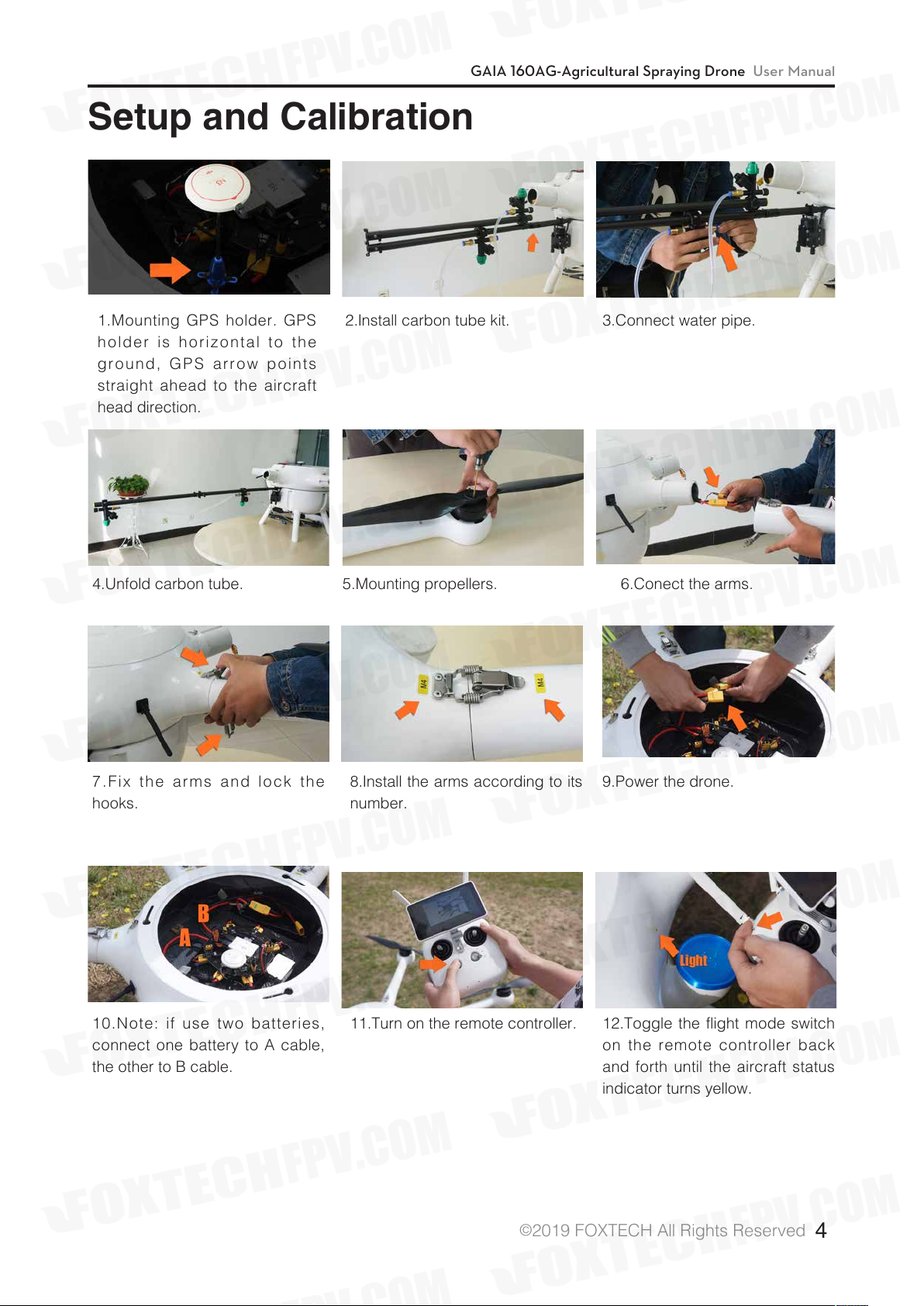
Setup and Calibration
GAIA 160AG-Agricultural Spraying Drone User Manual
1.Mounting GPS holder. GPS
holder is horizontal to the
ground, GPS arrow points
straight ahead to the aircraft
head direction.
4.Unfold carbon tube.
2.Install carbon tube kit.
5.Mounting propellers.
3.Connect water pipe.
6.Conect the arms.
7.Fix the arms and lock the
hooks.
10.Note: if use two batteries,
connect one battery to A cable,
the other to B cable.
8.Install the arms according to its
number.
11.Turn on the remote controller.
©
2019 FOXTECH All Rights Reserved
9.Power the drone.
12.Toggle the flight mode switch
on the remote controller back
and forth until the aircraft status
indicator turns yellow.
4
Page 6
GAIA 160AG-Agricultural Spraying Drone User Manual
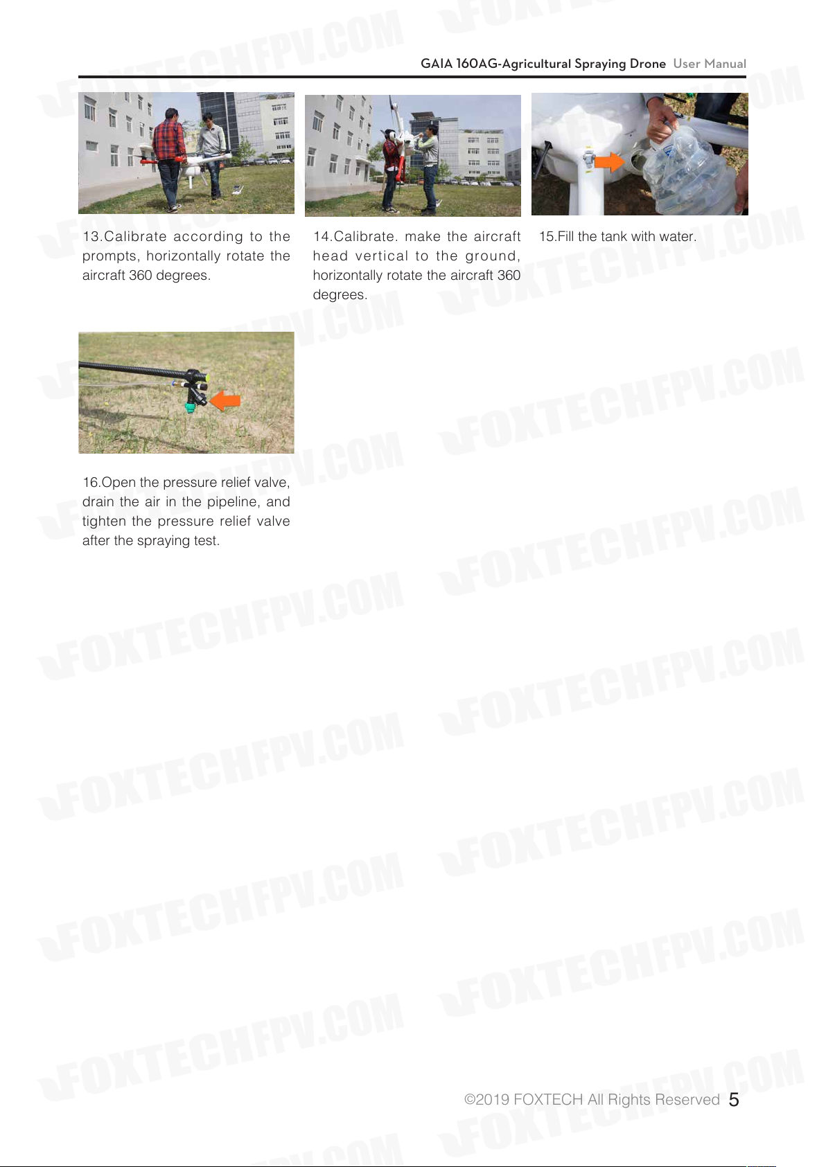
13.Calibrate according to the
prompts, horizontally rotate the
aircraft 360 degrees.
16.Open the pressure relief valve,
drain the air in the pipeline, and
tighten the pressure relief valve
after the spraying test.
14.Calibrate. make the aircraft
head vertical to the ground,
horizontally rotate the aircraft 360
degrees.
15.Fill the tank with water.
©
2019 FOXTECH All Rights Reserved
5
Page 7
GAIA 160AG-Agricultural Spraying Drone User Manual
Basic Theory
GAIA 160AG agriculture spraying drone is a high performance aircraft capable of offering comprehensive
solutions for agricultural care. GAIA 160AG is made of carbon fiber material which features light weight and
high strength, the top cover of the fuselage and the tank are made of glass fiber. The frame weight if about
7.25kg. The arm of GAIA160 series hexacopter is pluggable, both the cover and arms can be locked with
the quick locking hooks.
The big fuselage of GAIA 160AG makes it possible to install many equipments eg. battery, Gps, flight control
system. And all the wires are built into the fuselage. The closed fuselage structure can protect the GAIA
160AG hexacopter from the rain and dust, and also protect other load equipments.
This GAIA 160AG is equipped with a 2.8 meter long tube with four nozzles. The new water-saving nozzles
could save the pesticide and improve the efficiency of spraying at the same time. This GAIA 160AG has a
grid pesticide container which can prevent the liquids sloshing in the flight. The capacity of pesticide tank
is 22.5L, so do not need to add pesticide frequently. The propeller vortex can help the GAIA 160AG evenly
spraying the pesticide on the front and back of the plant leaves.
The GAIA 160AG is equipped with powerful motor and high efficiency 30 inch folding propeller, the max
lift of one rotor can reach 13kg. The total thrust is over 70kg. The GAIA 160AG supports both manual and
automatic flight, it can achieve automatic spraying by the planned flight paths. The motor and ESC use the
water-resistant design, and can be applied in different weather conditions. Because of the large liquids load
the efficiency of GAIA 160AG is twice as much as other aircraft with 10L payload.
The GAIA 160AG DJI AG 2.0 Version adopts N3-AG 2.0 flight controller and radar sensing system,
combined with the new spraying system and intelligent operation planning system, agricultural plant
protection efficiency is significantly improved. All these additions make plant protection more accurate and
efficient. The downward radar module adopts microwave technology which provides high-precision altitude,
so 160AG will fly above the crops at a constant spraying distance to ensure uniformity of the pesticide
spraying.
Version Upgrade: The legs of GAIA 160AG are lengthened to provide more space for installation of various
spraying equipment.
©
2019 FOXTECH All Rights Reserved
6
Page 8
GAIA 160AG-Agricultural Spraying Drone User Manual
N3-AG Introduction
The N3-AG Agriculture Flight Control System, based on the DJI N3 flight control system, is designed for
agriculture applications. It consists of flight controller, GNSS-Compass Pro, PMU(Power Management Unit)
and LED module.
N3-AG Parts
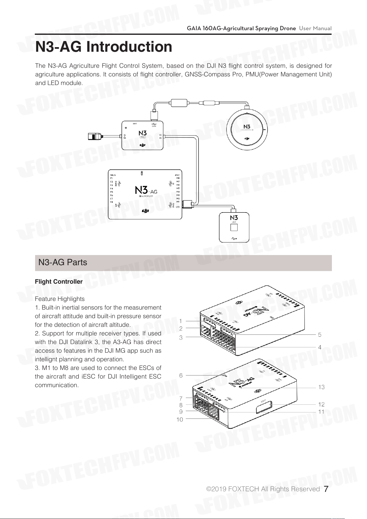
Flight Controller
Feature Highlights
1. Built-in inertial sensors for the measurement
of aircraft attitude and built-in pressure sensor
for the detection of aircraft altitude.
2. Support for multiple receiver types. If used
with the DJI Datalink 3, the A3-AG has direct
access to features in the DJI MG app such as
intellignt planning and operation.
3. M1 to M8 are used to connect the ESCs of
the aircraft and iESC for DJI Intelligent ESC
communication.
©
2019 FOXTECH All Rights Reserved
7
Page 9
GAIA 160AG-Agricultural Spraying Drone User Manual
Flight Controller
1. PMU Port
Derives power from the PMU module.
2. LED Port
Communicates with the LED module.
3. M1-M8 Pins
Connects to the corresponding ESC
PWM port for each motor.
4. iESC Port
Communicates with the DJI Smart ESC
using the Smart ESC Communication
Cable.
5. RF Port
Communicates with the DJI Datalink 3
Air System.
6. Status Indicator
Indicates the status of the flight controller.
GNSS-Compass Module
7. CAN2 Port
CAN Bus port (Reserved port).
8. S-Bus Port
Communicates with a DJI DR16 or S-Bus
receiver.
9. F1-F4 Pins
Multifunction PWM output ports.
10. F5-F8 Pins
Multifunction PWM I / O ports.
11. API Port
Reserved port.
12. EXP Port
Extended port (Communicates with the
A3 upgrade kit).
13. Orientation Arrow
The flight controller orientation arrow.
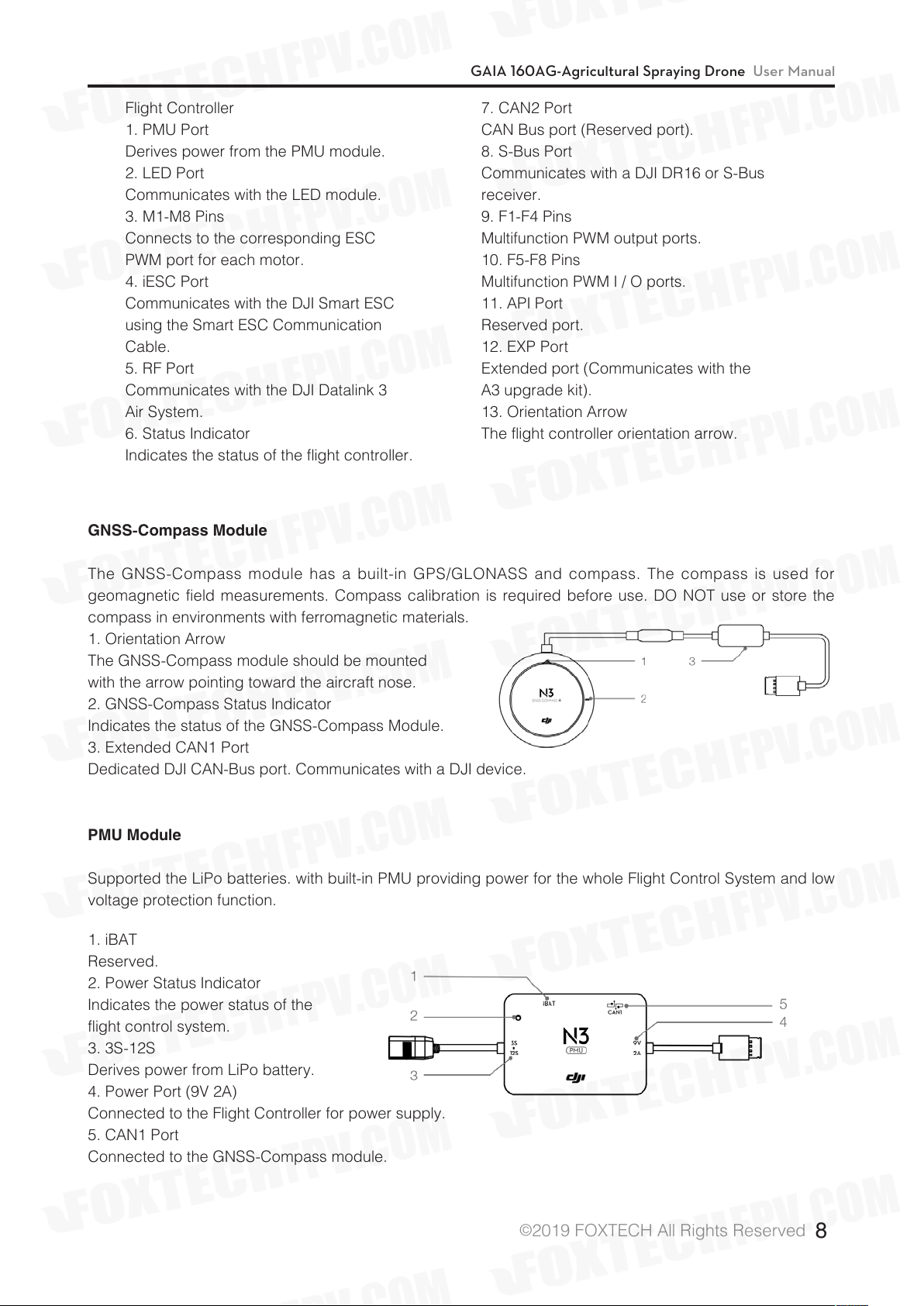
The GNSS-Compass module has a built-in GPS/GLONASS and compass. The compass is used for
geomagnetic field measurements. Compass calibration is required before use. DO NOT use or store the
compass in environments with ferromagnetic materials.
1. Orientation Arrow
The GNSS-Compass module should be mounted
with the arrow pointing toward the aircraft nose.
2. GNSS-Compass Status Indicator
Indicates the status of the GNSS-Compass Module.
3. Extended CAN1 Port
Dedicated DJI CAN-Bus port. Communicates with a DJI device.
PMU Module
Supported the LiPo batteries. with built-in PMU providing power for the whole Flight Control System and low
voltage protection function.
1. iBAT
Reserved.
2. Power Status Indicator
Indicates the power status of the
flight control system.
3. 3S-12S
Derives power from LiPo battery.
4. Power Port (9V 2A)
Connected to the Flight Controller for power supply.
5. CAN1 Port
Connected to the GNSS-Compass module.
©
2019 FOXTECH All Rights Reserved
8
Page 10
GAIA 160AG-Agricultural Spraying Drone User Manual
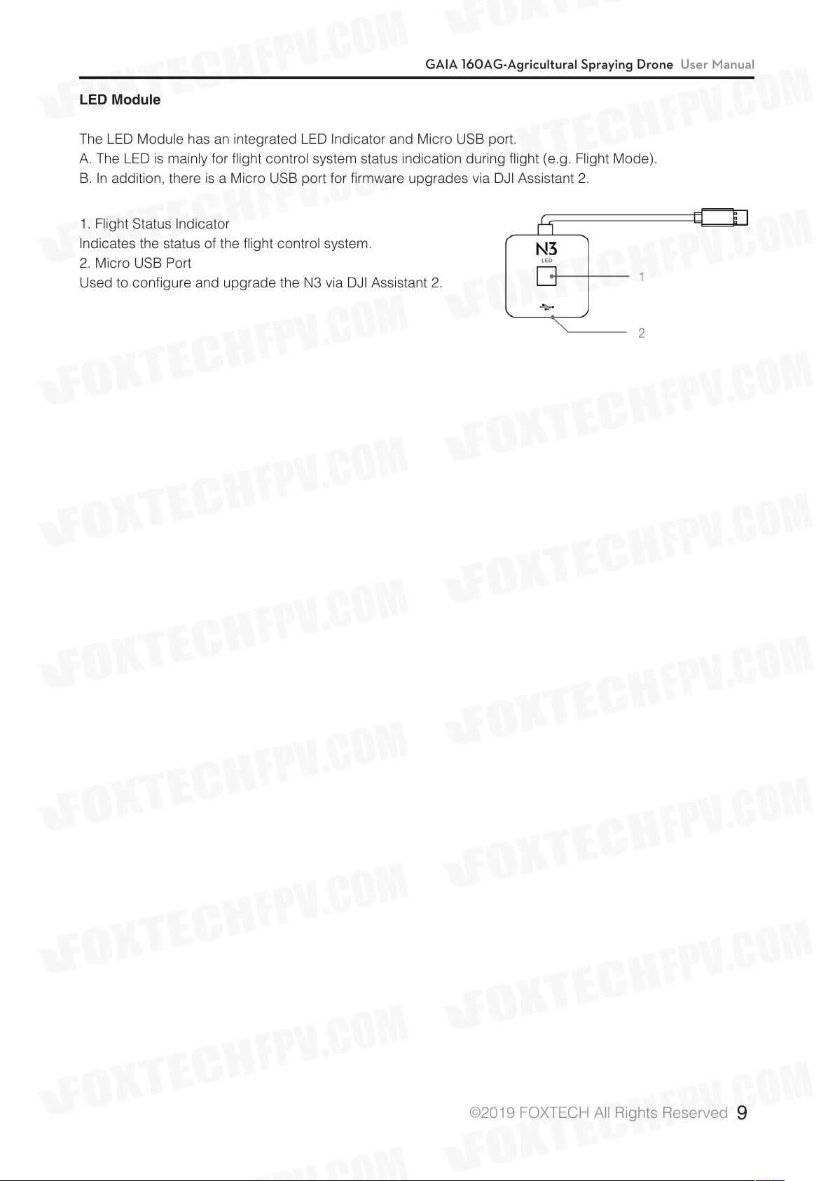
LED Module
The LED Module has an integrated LED Indicator and Micro USB port.
A. The LED is mainly for flight control system status indication during flight (e.g. Flight Mode).
B. In addition, there is a Micro USB port for firmware upgrades via DJI Assistant 2.
1. Flight Status Indicator
Indicates the status of the flight control system.
2. Micro USB Port
Used to configure and upgrade the N3 via DJI Assistant 2.
©
2019 FOXTECH All Rights Reserved
9
Page 11
GAIA 160AG-Agricultural Spraying Drone User Manual
AgricultureManagementUnit(AMUII)
Introduction
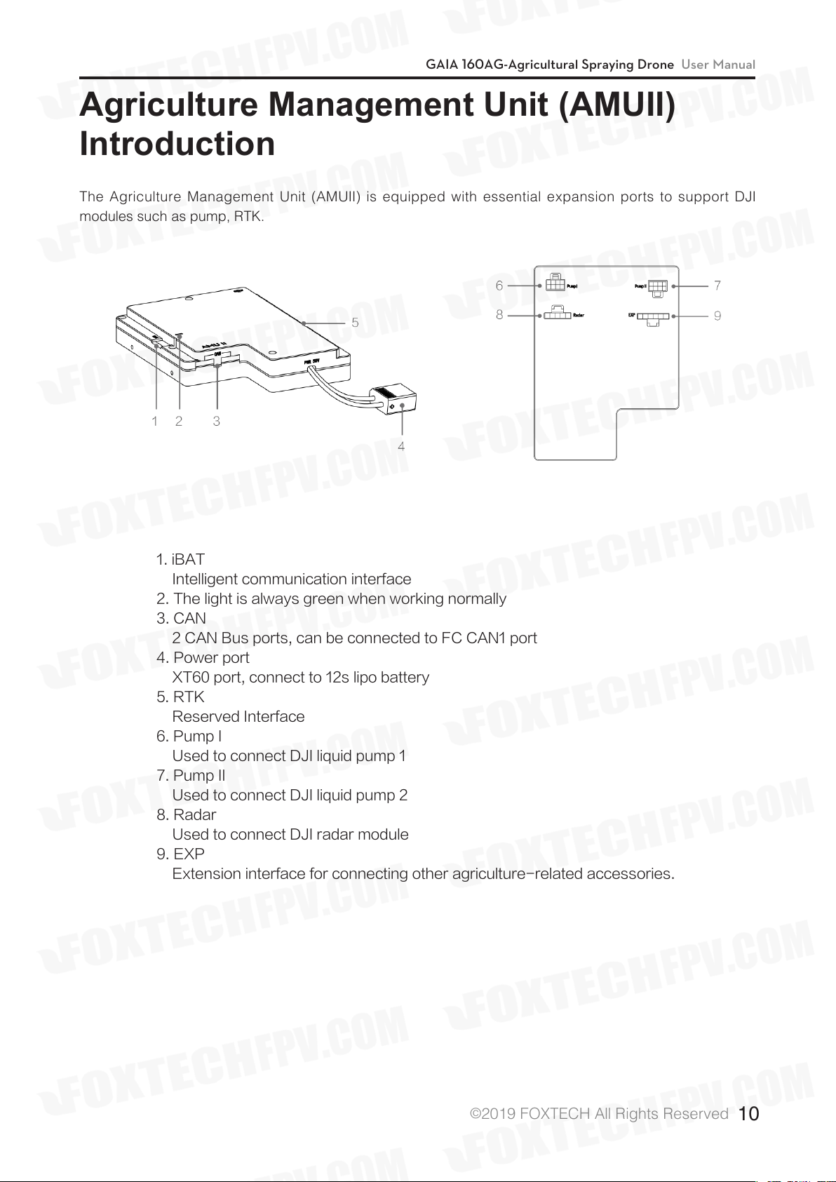
The Agriculture Management Unit (AMUII) is equipped with essential expansion ports to support DJI
modules such as pump, RTK.
1. iBAT
Intelligent communication interface
2. The light is always green when working normally
3. CAN
2 CAN Bus ports, can be connected to FC CAN1 port
4. Power port
XT60 port, connect to 12s lipo battery
5. RTK
Reserved Interface
6. Pump I
Used to connect DJI liquid pump 1
7. Pump II
Used to connect DJI liquid pump 2
8. Radar
Used to connect DJI radar module
9. EXP
Extension interface for connecting other agriculture-related accessories.
©
2019 FOXTECH All Rights Reserved
10
Page 12
RemoteController
GAIA 160AG-Agricultural Spraying Drone User Manual
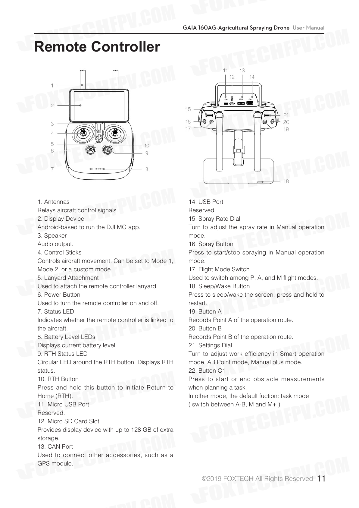
1. Antennas
Relays aircraft control signals.
2. Display Device
Android-based to run the DJI MG app.
3. Speaker
Audio output.
4. Control Sticks
Controls aircraft movement. Can be set to Mode 1,
Mode 2, or a custom mode.
5. Lanyard Attachment
Used to attach the remote controller lanyard.
6. Power Button
Used to turn the remote controller on and off.
7. Status LED
Indicates whether the remote controller is linked to
the aircraft.
8. Battery Level LEDs
Displays current battery level.
9. RTH Status LED
Circular LED around the RTH button. Displays RTH
status.
10. RTH Button
Press and hold this button to initiate Return to
Home (RTH).
11. Micro USB Port
Reserved.
12. Micro SD Card Slot
Provides display device with up to 128 GB of extra
storage.
13. CAN Port
Used to connect other accessories, such as a
GPS module.
14. USB Port
Reserved.
15. Spray Rate Dial
Turn to adjust the spray rate in Manual operation
mode.
16. Spray Button
Press to start/stop spraying in Manual operation
mode.
17. Flight Mode Switch
Used to switch among P, A, and M flight modes.
18. Sleep/Wake Button
Press to sleep/wake the screen; press and hold to
restart.
19. Button A
Records Point A of the operation route.
20. Button B
Records Point B of the operation route.
21. Settings Dial
Turn to adjust work efficiency in Smart operation
mode, AB Point mode, Manual plus mode.
22. Button C1
Press to start or end obstacle measurements
when planning a task.
In other mode, the default fuction: task mode
( switch between A-B, M and M+ )
©
2019 FOXTECH All Rights Reserved
11
Page 13
GAIA 160AG-Agricultural Spraying Drone User Manual
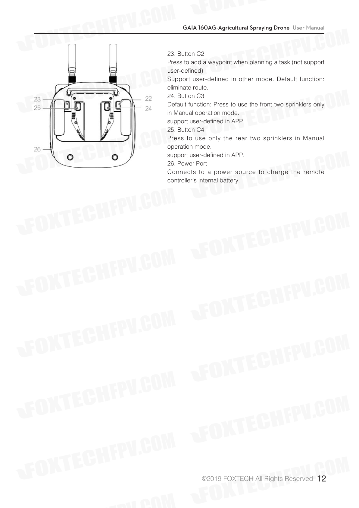
23. Button C2
Press to add a waypoint when planning a task.(not support
user-defined)
Support user-defined in other mode. Default function:
eliminate route.
24. Button C3
Default function: Press to use the front two sprinklers only
in Manual operation mode.
support user-defined in APP.
25. Button C4
Press to use only the rear two sprinklers in Manual
operation mode.
support user-defined in APP.
26. Power Port
Connects to a power source to charge the remote
controller’s internal battery.
©
2019 FOXTECH All Rights Reserved
12
Page 14
GAIA 160AG-Agricultural Spraying Drone User Manual
Installation
In this chapter use the N3-AG.
Overview
Installation Procedure
Read this section carefully and follow the procedures below to install your flight control system,
otherwise the flight control system may not normally work.
1 Ensure all parts are in good condition.
2 Mount the parts to your airframe and connect them properly.
3 Launch the DJI Assistant 2 and configure the parameters.
4 Ensure the motor, remote controller channels and Failsafe settings are correct.
5 Ensure the devices connected to the flight controller are working normally and correctly set in DJI
Assistant 2.
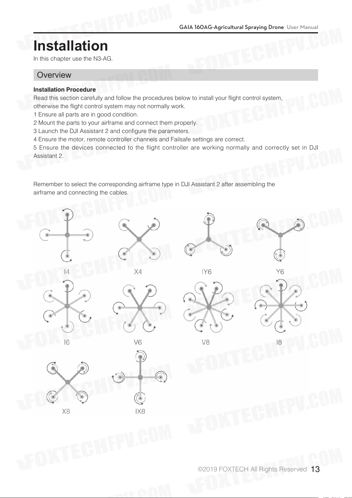
Remember to select the corresponding airframe type in DJI Assistant 2 after assembling the
airframe and connecting the cables.
©
2019 FOXTECH All Rights Reserved
13
Page 15
GAIA 160AG-Agricultural Spraying Drone User Manual
The arrow directions in the above diagram indicate the rotation direction of the motor/ propeller. Dark
colored arm (s) indicate the direction of the aircraft’s nose.
For coaxial propellers, dark colored propellers are at the top and gray colored propellers are at the
bottom. Otherwise, all propellers are at the top.
Make sure that the receiver and remote controller are linked properly before use. Be sure to link the receiver
and remote controller according by following all the procedures in the remote controller and receiver user
manual, and according to the configurations in DJI Assistant 2.
DJI Datalink 3
DJI Datalink 3 lets you use DJI MG app to configure the flight control system parameters and utilize
intelligent agricultural operation.
There is no need to enable the Failsafe function on the remote controller. Once the receiver loses
signal from the remote controller, the controller unit will enter Failsafe mode automatically, and the
aircraft will hover or return-to-home & land according to the Failsafe configurations in DJI Assistant 2.
ESC
ESC output should be 400Hz. DJI Propulsion systems are recommended.
The iESC port can connect to the DJI Smart ESC Communication Cable if using the DJI Intelligent ESC.
Propeller and Motor
It is required to use with Propeller and Motor of more than 2400rpm.
Battery
If using a LiPo battery (3S - 12S), only the voltage information and low voltage protection are available.
Preparing DJI Assistant 2
Download DJI Assistant 2
DJI Assistant 2 is used to configure the flight control system.
http://www.dji.com/agriculture-solution/info#downloads
Supports Windows 7 (or later) or Mac OS X 10.11 (or later).
Installing DJI Assistant 2
DJI Assistant 2 will guide you through setting the Flight Control System’s parameters. Carefully follow the on-
screen prompts to configure the Flight Control System.
Installing and Running on Windows
Supports Windows 7, Windows 8, Windows 10 (32 or 64 bit).
1. Connect the Micro USB port on the LED module to a PC via a Micro USB cable.
2. Run the software assistant installer and follow the prompts to finish installation.
3. Double click the software assistant icon on your Windows desktop to launch the software.
Installing and Running on Mac OS X
Supports Mac OS X 10.11 (or later).
1. Run the DMG installer and follow the prompts to finish installation.
2. If using Launchpad to run DJI Assistant 2 for the first time, Launchpad will not allow access because the
software has not been reviewed by the Mac App Store.
©
2019 FOXTECH All Rights Reserved
14
Page 16
GAIA 160AG-Agricultural Spraying Drone User Manual
3. Locate the DJI Assistant 2 icon in the Finder, press the Control key and then click the DJI Assistant 2 icon
(or right-click the DJI Assistant 2 icon using a mouse). Choose Open from the shortcut menu, click Open in
the dialog box and the software will launch.
4. After the first successful launch, direct launching of the software can be achieved by double-clicking the
DJI Assistant 2 icon in the Finder or using Launchpad.
DJI Assistant 2 works exactly the same way on Mac OS X and Windows. The DJI Assistant 2
screenshots that appear in this manual are taken from the Windows version.
For safety reasons, do not use the power battery for power supply or remove the propellers from
the motors before connecting to the Assistant Software.he Windows version.
Start the Installation
Important: Strictly follow the provided guidelines. Failure to do so may lead to unexpected flight behavior or
serious accidents.
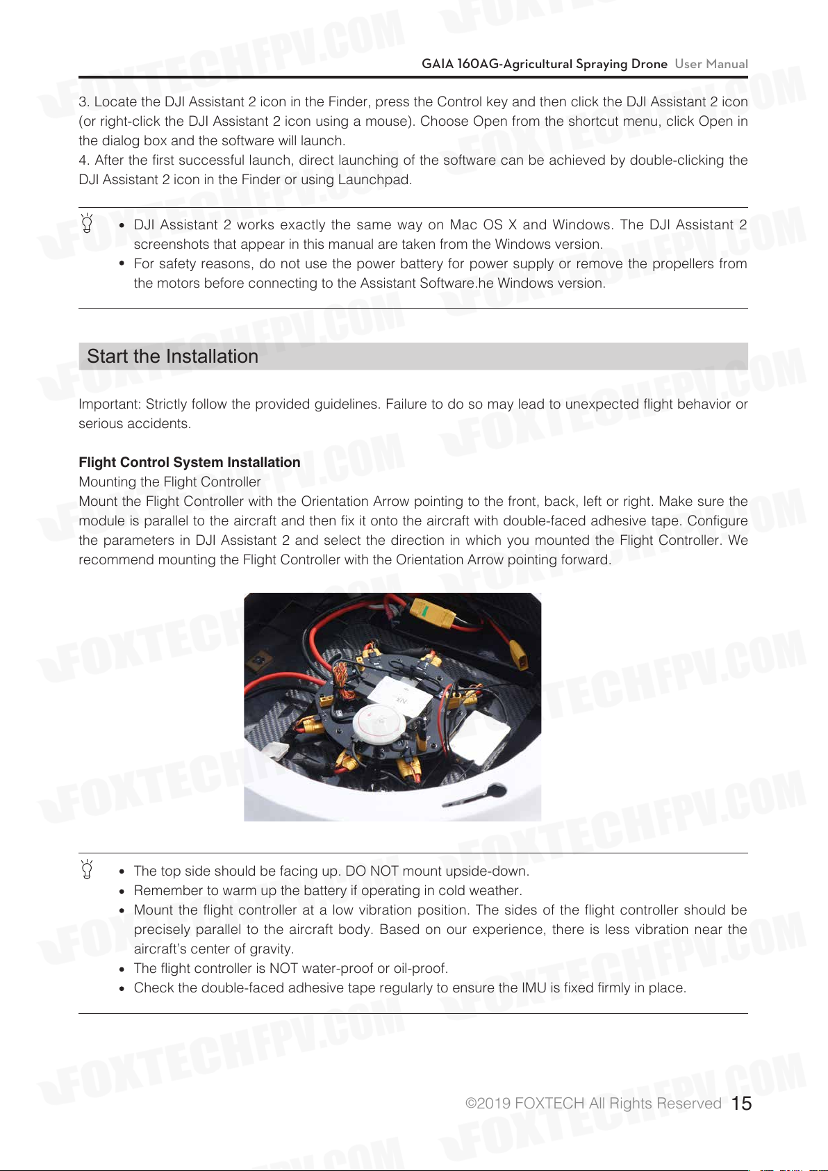
Flight Control System Installation
Mounting the Flight Controller
Mount the Flight Controller with the Orientation Arrow pointing to the front, back, left or right. Make sure the
module is parallel to the aircraft and then fix it onto the aircraft with double-faced adhesive tape. Configure
the parameters in DJI Assistant 2 and select the direction in which you mounted the Flight Controller. We
recommend mounting the Flight Controller with the Orientation Arrow pointing forward.
The top side should be facing up. DO NOT mount upside-down.
Remember to warm up the battery if operating in cold weather.
Mount the flight controller at a low vibration position. The sides of the flight controller should be
precisely parallel to the aircraft body. Based on our experience, there is less vibration near the
aircraft’s center of gravity.
The flight controller is NOT water-proof or oil-proof.
Check the double-faced adhesive tape regularly to ensure the IMU is fixed firmly in place.
©
2019 FOXTECH All Rights Reserved
15
Page 17
GAIA 160AG-Agricultural Spraying Drone User Manual
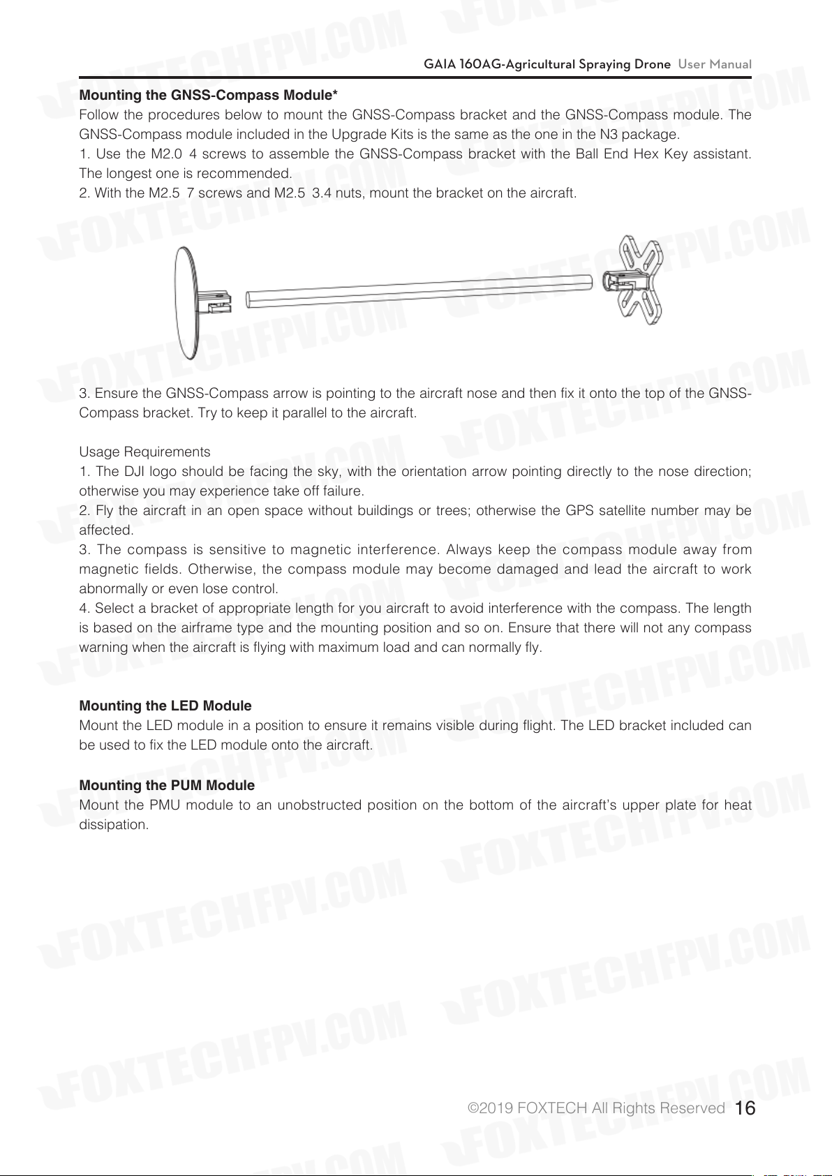
Mounting the GNSS-Compass Module*
Follow the procedures below to mount the GNSS-Compass bracket and the GNSS-Compass module. The
GNSS-Compass module included in the Upgrade Kits is the same as the one in the N3 package.
1. Use the M2.0×4 screws to assemble the GNSS-Compass bracket with the Ball End Hex Key assistant.
The longest one is recommended.
2. With the M2.5×7 screws and M2.5×3.4 nuts, mount the bracket on the aircraft.
3. Ensure the GNSS-Compass arrow is pointing to the aircraft nose and then fix it onto the top of the GNSS-
Compass bracket. Try to keep it parallel to the aircraft.
Usage Requirements
1. The DJI logo should be facing the sky, with the orientation arrow pointing directly to the nose direction;
otherwise you may experience take off failure.
2. Fly the aircraft in an open space without buildings or trees; otherwise the GPS satellite number may be
affected.
3. The compass is sensitive to magnetic interference. Always keep the compass module away from
magnetic fields. Otherwise, the compass module may become damaged and lead the aircraft to work
abnormally or even lose control.
4. Select a bracket of appropriate length for you aircraft to avoid interference with the compass. The length
is based on the airframe type and the mounting position and so on. Ensure that there will not any compass
warning when the aircraft is flying with maximum load and can normally fly.
Mounting the LED Module
Mount the LED module in a position to ensure it remains visible during flight. The LED bracket included can
be used to fix the LED module onto the aircraft.
Mounting the PUM Module
Mount the PMU module to an unobstructed position on the bottom of the aircraft’s upper plate for heat
dissipation.
©
2019 FOXTECH All Rights Reserved
16
Page 18
GAIA 160AG-Agricultural Spraying Drone User Manual
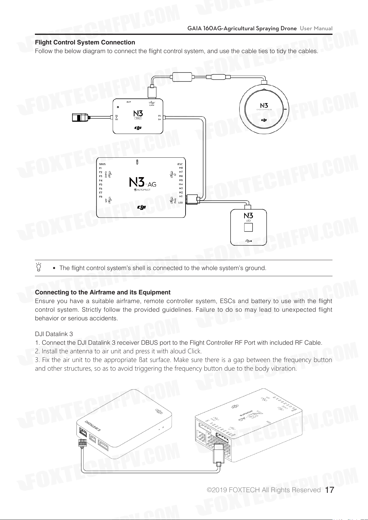
Flight Control System Connection
Follow the below diagram to connect the flight control system, and use the cable ties to tidy the cables.
The flight control system’s shell is connected to the whole system’s ground.
Connecting to the Airframe and its Equipment
Ensure you have a suitable airframe, remote controller system, ESCs and battery to use with the flight
control system. Strictly follow the provided guidelines. Failure to do so may lead to unexpected flight
behavior or serious accidents.
DJI Datalink 3
1. Connect the DJI Datalink 3 receiver DBUS port to the Flight Controller RF Port with included RF Cable.
2. Install the antenna to air unit and press it with aloud Click.
3. Fix the air unit to the appropriate ßat surface. Make sure there is a gap between the frequency button
and other structures, so as to avoid triggering the frequency button due to the body vibration.
©
2019 FOXTECH All Rights Reserved
17
Page 19
GAIA 160AG-Agricultural Spraying Drone User Manual
Be sure to install the antenna before powering up to avoid damage to the circuit.
When using, try to keep the antenna facing down and obstruct the obstacles, avoiding the
communication distance being shortened due to blocking or even can't communicate.
Be sure to use the speciÞed model antenna and ensure proper installation. forbidden to use other
types of antennas.
When connecting the air unit antenna and the antenna extension cable, be careful to avoid
damage to the connector.
When removing the sky end antenna, be sure to use pliers to force the metal part of the antenna
connector. Do not pull on the feeder to avoid damage to the antenna.
Connecting to the ESCs
1. Connect the M1-M6 ports on the bottom board to the M1-M6 ports on the Flight Controller in order.
Other types of aircraft connections
Connect to the ESC interface in sequence according to the actual number of ESCs.
When powering up for the first time, please power on the flight control and the ESC power supply
at the same time to ensure that the flight control successfully addresses the ESC.
If you need to replace some ESCs, you need to repeat this operation at least once to ensure that
the ESC is successfully addressed.
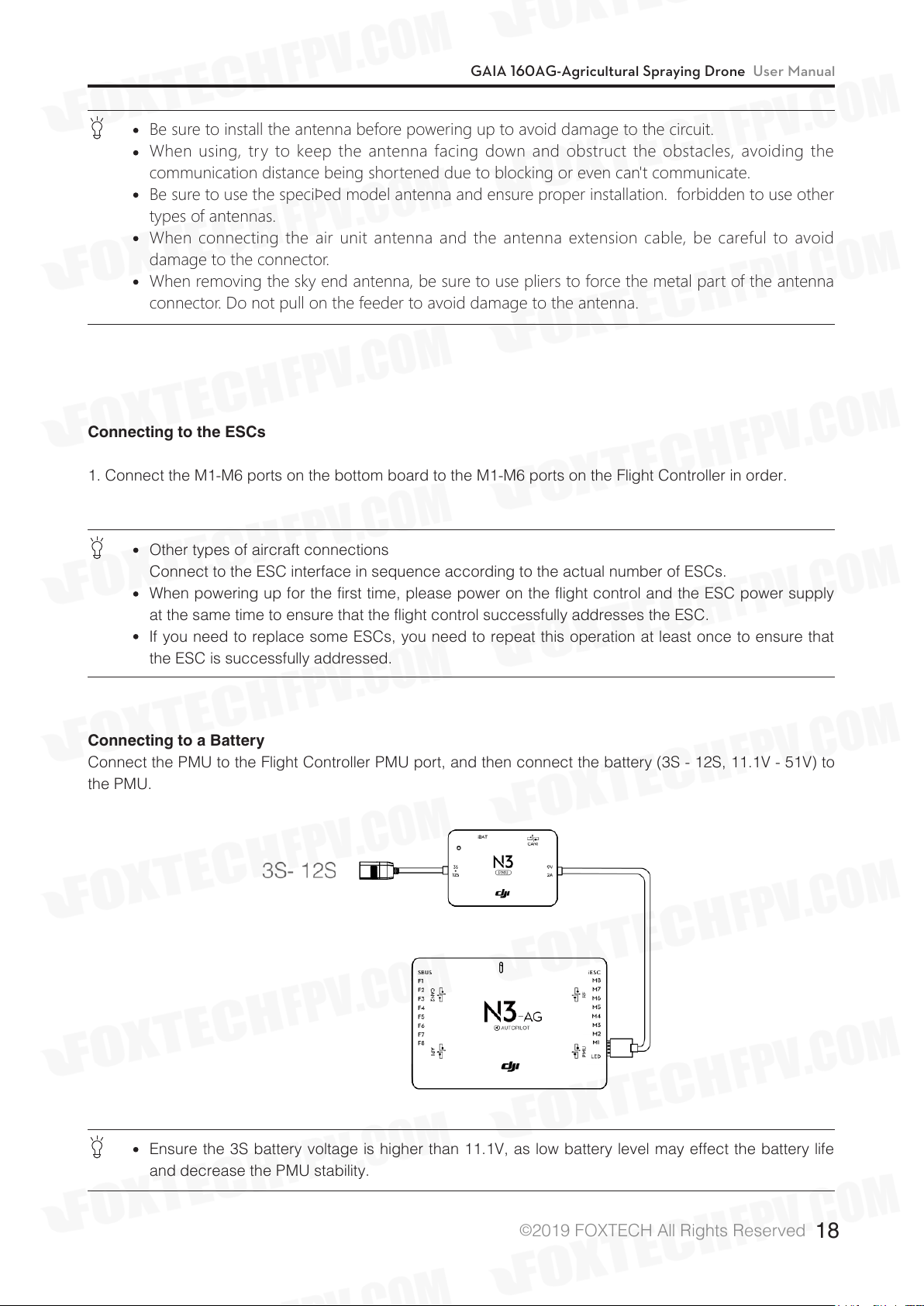
Connecting to a Battery
Connect the PMU to the Flight Controller PMU port, and then connect the battery (3S - 12S, 11.1V - 51V) to
the PMU.
Ensure the 3S battery voltage is higher than 11.1V, as low battery level may effect the battery life
and decrease the PMU stability.
©
2019 FOXTECH All Rights Reserved
18
Page 20
GAIA 160AG-Agricultural Spraying Drone User Manual
AMUII Installation
Installation
Mount the AMU to an appropriate position on the aircraft for heat dissipation.
Connection
1. Connect the CAN Bus port on the AMU to the CAN1 port on the flight controller or extended CAN1 port
on the GNSS-Compass / GPS-Compass Pro module via the included CAN-Gimbal cable.
2. Connect the power port on the AMU to the power supply of the aircraft via an appropriate cable.
Connect to Expansion Devices
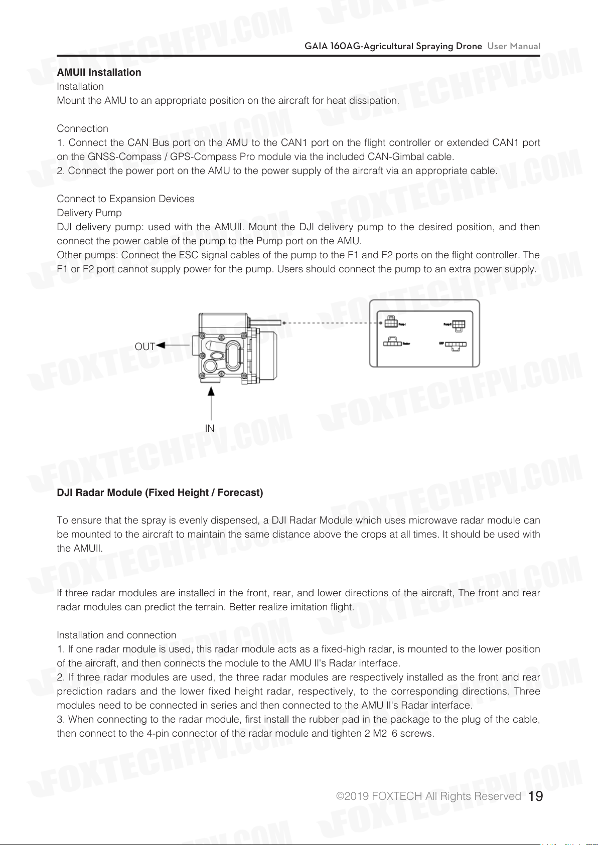
Delivery Pump
DJI delivery pump: used with the AMUII. Mount the DJI delivery pump to the desired position, and then
connect the power cable of the pump to the Pump port on the AMU.
Other pumps: Connect the ESC signal cables of the pump to the F1 and F2 ports on the flight controller. The
F1 or F2 port cannot supply power for the pump. Users should connect the pump to an extra power supply.
OUT
IN
DJI Radar Module (Fixed Height / Forecast)
To ensure that the spray is evenly dispensed, a DJI Radar Module which uses microwave radar module can
be mounted to the aircraft to maintain the same distance above the crops at all times. It should be used with
the AMUII.
If three radar modules are installed in the front, rear, and lower directions of the aircraft, The front and rear
radar modules can predict the terrain. Better realize imitation flight.
Installation and connection
1. If one radar module is used, this radar module acts as a fixed-high radar, is mounted to the lower position
of the aircraft, and then connects the module to the AMU II's Radar interface.
2. If three radar modules are used, the three radar modules are respectively installed as the front and rear
prediction radars and the lower fixed height radar, respectively, to the corresponding directions. Three
modules need to be connected in series and then connected to the AMU II's Radar interface.
3. When connecting to the radar module, first install the rubber pad in the package to the plug of the cable,
then connect to the 4-pin connector of the radar module and tighten 2 M2×6 screws.
©
2019 FOXTECH All Rights Reserved
19
Page 21
GAIA 160AG-Agricultural Spraying Drone User Manual
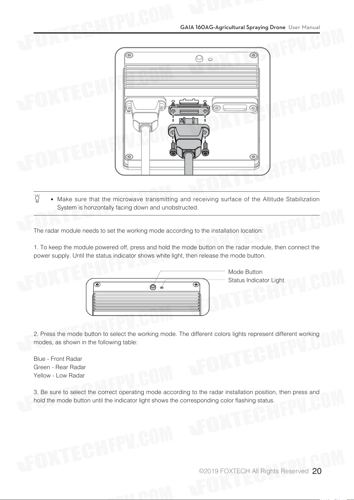
Make sure that the microwave transmitting and receiving surface of the Altitude Stabilization
System is horizontally facing down and unobstructed.
The radar module needs to set the working mode according to the installation location:
1. To keep the module powered off, press and hold the mode button on the radar module, then connect the
power supply. Until the status indicator shows white light, then release the mode button.
Mode Button
Status Indicator Light
2. Press the mode button to select the working mode. The different colors lights represent different working
modes, as shown in the following table:
Blue - Front Radar
Green - Rear Radar
Yellow - Low Radar
3. Be sure to select the correct operating mode according to the radar installation position, then press and
hold the mode button until the indicator light shows the corresponding color flashing status.
©
2019 FOXTECH All Rights Reserved
20
Page 22
GAIA 160AG-Agricultural Spraying Drone User Manual
DJI Liquid Indicator
Install the level gauge in a suitable position inside the spray box and wire it to the 5-pin connector of the
fixed height radar module below the aircraft.
DJI high-precision radar obstacle avoidance module (optional)
1.According to the detection range of the obstacle avoidance module, install it in a proper position, taking
care not to block the obstacle avoidance module, so as not to affect the use.
2. Attach the rubber pad to the plug of the obstacle avoidance module cable, then connect the cable to the
4-pin connector of the fixed height or predictive radar module and tighten the 2 M2×6 screws.
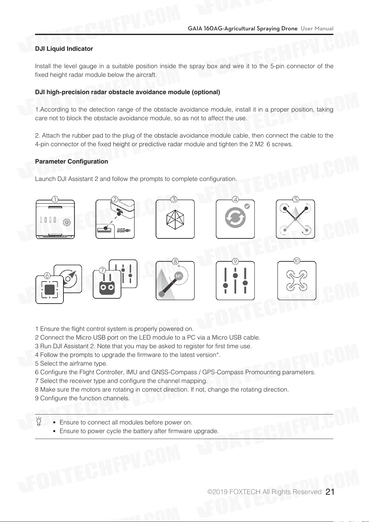
Parameter Configuration
Launch DJI Assistant 2 and follow the prompts to complete configuration.
1 Ensure the flight control system is properly powered on.
2 Connect the Micro USB port on the LED module to a PC via a Micro USB cable.
3 Run DJI Assistant 2. Note that you may be asked to register for first time use.
4 Follow the prompts to upgrade the firmware to the latest version*.
5 Select the airframe type.
6 Configure the Flight Controller, IMU and GNSS-Compass / GPS-Compass Promounting parameters.
7 Select the receiver type and configure the channel mapping.
8 Make sure the motors are rotating in correct direction. If not, change the rotating direction.
9 Configure the function channels.
Ensure to connect all modules before power on.
Ensure to power cycle the battery after firmware upgrade.
©
2019 FOXTECH All Rights Reserved
21
Page 23
GAIA 160AG-Agricultural Spraying Drone User Manual
SystemFunctions
Flight Modes
The flight control system includes two flight modes: P-mode (Positioning) and A-mode (Attitude). Toggle the
Flight Mode switch on the remote controller to one of the two modes.
P-mode (Positioning): The aircraft uses GNSS for positioning and it can only maintain attitude stabilization
when GNSS signal is weak. In P-mode, users can start the motors, record Point A and B, and enter Smart
operation mode (A-B Route) when the GNSS signal is strong. If using the D-RTK*, it can provide centimeter-
level positioning accuracy.
A-mode (Attitude): GNSS is not used for positioning, and aircraft can only maintain altitude using the
barometer. Aircraft can still record its position and return to the Home Point if a GNSS signal is present.
Attention in Attitude mode
The aircraft will enter attitude mode in the following two situations:
Passive mode: GNSS satellite signal difference or compass is disturbed.
Active mode: The user cuts the remote control flight mode to A position.
In attitude mode, the aircraft is susceptible to external interference, which will cause drift in the horizontal
direction; and some functions will not be available. Therefore, in this mode, the aircraft itself cannot achieve
fixed-point hovering, and the user needs to manually control the remote controller to realize the aircraft
hovering. In this mode, the handling difficulty of the aircraft will be greatly increased. If you want to use
this mode,must be familiar with the behavior of the aircraft in this mode and be able to control the aircraft
skillfully.
Do not fly the aircraft too far away, that will cause the lost of judgment of the aircraft attitude and cause a
risk.
Once passively entering this mode, it should land to a safe place as soon as possible to avoid an accident.
At the same time, should avoid to fly at narrow space where the the GNSS satellite signal is weak,to avoid
passive entry into the attitude mode, resulting in flight accidents.
Operation Modes
The system provides Smart, Manual, and Manual Plus
operation modes. Switch to one of the three modes via the Operation Mode switch on the remote controller.
Route Planning Mode
In Smart operation mode, the aircraft will travel along a pre-planned route. Operation resumption, data
protection, and the Altitude Stabilization System are available in this mode. The spray rate will be adjusted
automatically according to the flying speed. Smart operation mode is recommended for large, rectangular
spray areas.
©
2019 FOXTECH All Rights Reserved
22
Page 24
GAIA 160AG-Agricultural Spraying Drone User Manual
Field Planning
Users can plan the field by using the remote controller for different apploications.
Flight Planning
The user can control the aircraft to the desired position, then add a waypoint through the remote control or
App button to measure the edge of the farm and obstacles.
1. Power on the remote controller and enter the DJI MG app.
2. Click "Field Planning", chose "Flight Planning".
3. Wait until GNSS signal is strong.
4. Tap Start Measuring. Walk along the edge of the target field. Tap “Add Waypoint” or press Button C2 on
the back of the remote controller.
5. Mark any obstacles:
Use two methods below to mark obstacles if there is any in the target field.
Tap Start Obstacle Measurement C1 onscreen or press the C1 button on the back of the remote controller,
walk around the obstacle, and then tap End Obstacle Measurement C1 onscreen or press the C1 button
again.
Tap Start Obstacle Measurement C1 onscreen or press the C1 button on the back of the remote controller,
walk around the obstacle, and tap Add Waypoint C2 onscreen or press the C2 button to add waypoints. Tap
End Obstacle Measurement C1 onscreen or press the C1 button when finished.
6. Continue measuring the field by walking along the edge and adding waypoints at each corner of the field.
Tap End Measurement when the field has been measured and all obstacles have been marked. The DJI MG
app will produce a flight route according to the field's perimeter and obstacles.
7. Add calibration point(s): Walk to the location of each calibration point. Tap Add Calibration Point. The
calibration points are used to offset the bias of the flight route caused by the positioning difference between
the remote controller and aircraft. Choose at least one existing landmark as the fixed reference point(s) for
calibration when executing the same task. If none are available, use an easily identifiable object, such as a
metal stake.
×
Remote control planning
Users need to use the remote control to walk along the edge of farmland or obstacles for measurement. For
your safety, make sure that the aircraft is powered off when planning with the remote control.
1.Turn on the remote control and enter the main interface of the app. Click “Field Planning” and select
“Remote Plan”.
2. Ensure that the number of satellites is greater than or equal to 10 and the positioning accuracy is within 4
meters. The rest of the steps are the same as the flight plan, just take the remote control to walk instead of
manipulating the aircraft.
Task Editing
Tap any blank space onscreen to enter Edit Status.
1. Edit Waypoints
Move: Drag the waypoint to move.
Fine Tuning: Tap the waypoint to show Fine Tuning buttons. Tap to adjust.
Delete: Tap twice to delete a waypoint.
×
×
©
2019 FOXTECH All Rights Reserved
23
Page 25
GAIA 160AG-Agricultural Spraying Drone User Manual
2. Adjust Route
Route Direction: Tap and drag the icon near the route to adjust the flight direction of the produced route.
Line Spacing: Tap the icon at the top of the screen to adjust the line spacing between two neighboring
lines.
Safety Distance: Tap the icon on top of the screen, and then adjust the safety distance between the route
and the edge of the field or obstacle in Aircraft Settings.
3. Edit Obstacles
Tap and hold the marked obstacle or the position that needs to mark an obstacle on the screen to choose
the shape and size of the obstacle in the menu.
Tap the obstacle on the screen which has waypoints added, then follow the Edit Waypoints instructions to
edit the added waypoints for complete obstacle information.
If a route error appears in the app after importing data from the mapper to the remote controller, it is
because of the short distance between two obstacles. Edit the obstacles in
the app to clear this error.
4. Tap “Save”, and then name the task, choose crop, and configure other parameters.
Starting a Task
1. Place the aircraft at one of the previously set calibration points and then power it on.
2. Click "Start a task"in DJI MG app main interface,go to Operation interface.
3. Tap Task List onscreen, choose a previously saved task, and then tap Use Task.
4. Tap Rectify Offset and then Rectify Aircraft Position, or adjust the route position via the Fine Tuning
buttons and then click OK.
5. Click Start, and set working parameters , and then click OK.
6. Takeoff and start the task.
If manually fly the aircraft to the targeted height, a Slide to Execute prompt will appear onscreen. Slide to
start spraying.
If the aircraft is on the ground, a Slide to Takeoff prompt will appear onscreen. Slide to takeoff and start
spraying.
Be sure to takeoff in open areas.
The task will be automatically cancelled if the motors are started before beginning the task. You will
need to recall the task in the task list.
Once started, the aircraft will fly to the starting point of the route and lock its heading in the
direction of the first turning point for the duration of the flight path.
During the task, the aircraft automatically sprays liquid while flying forwards or backwards, and it
doesn’t spray liquid while flying left and right. Users can adjust work efficiency (flying speed and
spray rate included) and height above the crops in the DJI MG app.
During the execution of the job, the user can stop the operation by dialing the emergency stop
switch. The aircraft will hover in place and record the breakpoint coordinates, at which point the
user is free to manipulate the aircraft. After that, the user can click the Continue button in the
App, and the aircraft will automatically fly back to the break coordinate point to continue the job.
It is important to pay attention to flight safety during the flight back to the interrupted coordinate
point. If the option to allow the switching of the flight mode is turned on in the assistant software,
the emergency stop switch is used as the flight mode switch, and the toggle switch may enter the
attitude mode, and the aircraft must be carefully operated.
The aircraft will hover at the ending point of the flight route after the task is completed.
©
2019 FOXTECH All Rights Reserved
24
Page 26

GAIA 160AG-Agricultural Spraying Drone User Manual
A-B Point Mode
In the A-B point mode, the aircraft can fly and spray pesticides according to specific routes, with job
recovery and data protection functions, and can use the radar module for height Fixed and obstacle
avoidance. Users can adjust working efficiency (including aircraft speed and spray flow) in real time on the
App interface. This mode is suitable for working in a large area with a shape close to a rectangle.
Operation Route
The aircraft will travel along a pre-designated square zig-zag route after recording turning points A and B.
Under optimal working conditions for the Altitude Stabilization System, the aircraft maintains distance from
the vegetation. The length of the dotted lines, called Operation Gap (Line Spacing), can be adjusted in DJI
Assistant 2 or the DJI MG app.
Operation Procedure
Maintain line of sight of the aircraft at all times.
Set the Flight Mode switch to P when GNSS signal is strong. Otherwise, Smart operation mode may
be unreliable.
Always inspect operating environments before flying.
Make sure that the GNSS signal is good, the DJI MG App's working mode toggle button is selected as the
“M” manual mode, and the interface displays the manual job (GNSS). Then aircraft is then taken off to the
appropriate height.
1. Record Points A and B in Order
Users cannot set the Operation Mode switch to Smart operation mode until they have recorded points A
and B.
Fly the aircraft to the starting point, depicted as Point A/B, hover, and then press Button A/B on the remote
controller or tap Point A/B onscreen. The icon for Point A/B will change from gray to purple and the Aircraft
Status Indicator will blink red/green after recording the starting points.
©
2019 FOXTECH All Rights Reserved
25
Page 27

GAIA 160AG-Agricultural Spraying Drone User Manual
Points A and B can only be recorded when the aircraft is hovering in Manual operation mode.
Update Point B by flying the aircraft to a new position to record. Note that if you update Point A,
you must also update Point B.
It is recommended to keep the direction of Point A to B parallel to one side of the rectangular spray
area for optimal effect.
After recording Point A, there will be a menu prompt for work type settings. Set the amount of
pesticide per acre and work type. Use the slider to adjust work efficiency. During the task, tap
the icon at the top of the screen to adjust parameters. You can also adjust work efficiency via the
Settings dial on the remote controller.
The DJI MG app will display an icon of line spacing. Tap to adjust the value. The line spacing
cannot be adjusted during operation. Switch to Manual or Manual Plus operation mode to adjust
the value, then go back to Smart operation mode.
2. Select the Route
Press the C1 or C2 buttons on the remote controller to select the operating pattern. Press C1 for Route L
and C2 for Route R. The default route pattern is Route R if no selection has been made.
Users can select the route in Manual operation mode only. If the aircraft is in Smart operation
mode, select the route after switching to Manual operation mode.
3. Configuring Aircraft Altitude
Click on the icon above the App interface to set the desired relative crop height. After the A-B point
operation is performed, if the working conditions are met, the radar module will automatically set the height
so that the aircraft remains at the same height as the crop while flying.
4. Performing task
Click "Start" in the lower right corner of the App interface and slide to automate the job.
If, after recording Points A and B, you fly the aircraft more than five meters away from Point B. Tap
Resume, and the aircraft will automatically fly to Point B to re-enter route.
During the operation, if the GNSS signal is weak, the aircraft enters the attitude mode and exits the
A-B point operation. Users need to carefully control the aircraft. When the GNSS signal is restored,
the user can choose to continue the job.
During the A-B point operation, if the A or B key is pressed when the aircraft speed is less than
0.3 m/s, the data of points A and B on the current working route will be cleared and the aircraft will
hover.
The job line spacing defaults to 5 meters and can be set in the app from 3 - 10 meters.
In the A-B point mode, the aircraft nose will always remain in the direction from A to B by default,
and the user can switch in the apps to always follow the flight direction (coming soon). However,
during the whole process of the operation, the user cannot control the heading of the aircraft.
When using the control sticks to control the aircraft during the operation, the aircraft will
automatically switch to Manual operation mode, complete corresponding flight behavior, and then
hover. To resume the A-B point task, tap Resume onscreen. The aircraft will return to operation
route, then resume flying along the operation route.
During the operation, if the radar module obstacle avoidance function is not turned on, the user
can using stick to control the front, rear, left and right direction of the aircraft and the throttle to
avoid obstacles on the working route.
In the process of operation, the aircraft will not spray pesticides when flying along the route of the
operating line spacing, and spray pesticides automatically when flying on the rest routes.
©
2019 FOXTECH All Rights Reserved
26
Page 28

GAIA 160AG-Agricultural Spraying Drone User Manual
5. Starting the Operation
a. Press the remote controller’s C1 and C2 buttons simultaneously. The aircraft will align with the line
between Points A and B with its heading pointing toward Point B. Fly laterally from Point B to L1/R1, then
hover at Point L1/R1 and wait for further instructions.
b. Repeat the previous step and the aircraft will fly to the next turning point along Route L/R and hover.
c. Enable Continuous Smart operation mode by pressing and holding the C1 and C2 buttons simultaneously
for 2-4 seconds when the aircraft is hovering at any given turning point. The Aircraft Status Indicator will
turn solid purple for one second. The aircraft will then fly along Route L/R continuously. The DJI MG app will
display the A-B Route.
d. To exit Continuous Smart operation mode, press and hold the C1 and C2 buttons simultaneously for 2-4
seconds. The aircraft will fly to the next turning point and hover.
If GNSS signal is weak during operation, the aircraft will automatically switch to Attitude mode. Exit
Smart operation mode and control the aircraft manually. When the aircraft regains a strong GNSS
signal, it will automatically fly to the next turning point.
If you press the A or B buttons during operation, the data for Points A and B of the current route will
be erased and the aircraft will hover in place.
The line spacing can be customized from 3-10 m in DJI MG. It is set to a length of 5 m by default.
Even though the heading of the aircraft cannot be adjusted, use the control sticks to avoid
obstacles. Refer to Manual Obstacle Avoidance for details.
The aircraft automatically sprays liquid when flying forwards or backwards, and does not spray
when flying left or right or when hovering.
Manual Operation Mode
Set the Operation Mode switch to M to enter Manual operation mode. You can control all the movements
of the aircraft, spray liquid via the remote controller’s Spray switch/button, and adjust the spray rate via the
remote controller’s Spray Rate knob/dial. Manual operation mode is ideal when the operating area is small.
Manual Plus Operation Mode
Set the Operation Mode switch to M+ to enter Manual Plus operation mode. The aircraft's' Maximum flying
speed is 7m/s (customizable in DJI Assistant 2 or the DJI MG app), the heading is locked, and all other
movement can be manually controlled in this mode. Press the C1 or C2 buttons on the remote controller to
steer the aircraft left or right. The aircraft sprays liquid automatically when flying forward or backward, and
does not spray when flying left and right. Manual Plus operation is ideal for irregularly-shaped operating
areas.
1. If using the Altitude Stabilization System, elevate the aircraft to the desired altitude within the working
range of the Altitude Stabilization System (2-3.5 m) before entering Manual Plus operation mode. The
Altitude Stabilization System starts working automatically by maintaining the spraying distance between the
aircraft and the vegetation below. Refer to Altitude Stabilization System for details.
2. Set the Operation Mode switch to M+ to activate Manual Plus operation mode.
The user needs to set the job spacing before operating the task. The job spacing is not adjustable
during the operation.
When using the App or remote control button to make the aircraft fly to the left or right
automatically, the left and right areas of the aircraft may be in the blind area of the radar module,
and obstacles cannot be detected. Users must be careful.
Spray rate will be adjusted automatically according to the flying speed.
Maximum spray rate, maximum flying speed, line spacing, and height above the crop can be
adjusted in the DJI MG app.
The aircraft cannot be controlled when using the C1 or C2 switches/buttons to steer the aircraft to
the left or right. Switch to Manual operation mode in case of emergency, and the aircraft will stop
flying.
©
2019 FOXTECH All Rights Reserved
27
Page 29

GAIA 160AG-Agricultural Spraying Drone User Manual
Operation Resumption
When exiting Smart Operation Mode or a route task, the aircraft will record a breakpoint. The Operation
Resumption function allows you to pause an operation temporarily (e.g., to refill the spray, change battery,
and avoid obstacles manually) and then resume operation at the breakpoint.
Instructions
Recording a Breakpoint
Exit Smart operation mode or F-mode through one of the following methods and the aircraft will record its
location as a breakpoint if GNSS signal is strong:
1. Click the “Pause” button or the “End” button in the lower right corner of the App; (Note: Clicking the “End”
button during A-B point work will end the job directly, and will not record the interrupted coordinate points,
nor can you continue the operation.)
2. The aircraft enters the return process in any way;
3. Push the emergency stop switch / flight mode switch;
4. The remote control pitch or roll stick has a striking action;
5. Obstacles are detected and the aircraft's emergency brake enters the obstacle avoidance mode;
6. The radar module obstacle avoidance function is turned on, but the radar abnormality is detected and
cannot work normally;
7. The aircraft reaches a limit value of height or distance;
8. No pesticide in working box;
9. If the GNSS signal is weak, the aircraft enters the attitude mode, exits the route operation or the A-B point
operation, and records the position of the time when the last GNSS signal is good.
Ensure that GNSS signal is strong when using the Operation Resumption function. Otherwise, the
aircraft cannot record and return to the break point.
Resume Operation
1. Exit the route operation mode or the A-B point operation mode by any of the above methods, and the
aircraft records the interruption coordinate point.
2. After the aircraft has been operated or if the conditions for triggering the recording of the break
coordinate point have been removed, the aircraft is maneuvered to the appropriate position.
3. Click the "Continue" button in the lower right corner of the app to continue.
4. Return route of the aircraft
If the current position of the aircraft is in the work area, the App will pop up the option, and the user can
choose to fly back directly to the break coordinate point or along the path of the vertical work route to return
to the original route ( fly back to the projection point). If the current position of the aircraft is not in the work
area, the aircraft directly flies back to the break coordinate point and continues the work.
5. If obstacle avoidance is required during the return procedure, users can control the aircraft forwards,
backwards, left, and right. Refer to Manual Obstacle Avoidance for details.
©
2019 FOXTECH All Rights Reserved
28
Page 30

GAIA 160AG-Agricultural Spraying Drone User Manual
Typical Applications
In Smart operation mode or F-mode, users can control the aircraft forward, backward, left, and right,
avoiding obstacles along the operation route, or in an emergency (e.g., abnormal aircraft behavior). The
following instructions describe how to avoid obstacles manually:
Manual Obstacle Avoidance
1. Exit Smart Operation Mode or F-mode
In the two modes, when using the control sticks to control the aircraft forward, backward, left or right (i.e.,
push the pitch or roll stick), the aircraft will automatically exit the current mode, pause the task and record
the current position as a breakpoint (Point C), then complete the corresponding flight behavior and hover.
When pushing the control sticks to exit Smart Operation mode, the aircraft will need a braking
distance. Ensure that there is a safe distance between the aircraft and any obstacles.
2. Avoid an Obstacle
After switching to Manual operation mode, users can control the aircraft to avoid the obstacle from Point C
to D.
3. Resume Operation
Enter the corresponding mode, and then tap Resume in the DJI MG app. If the aircraft is in the operating
area, there will be a prompt in the DJI MG app. Select Fly to Project Point. If the aircraft is out of the
operating area, it will return straight to the breakpoint and resume the operation.
To avoid risk, ensure that the aircraft has completely avoided the obstacle before resuming
operation.
In the event of an emergency, ensure that the aircraft is in normal status and then fly the aircraft
manually to a safe area to resume operation.
Repeat the instructions above to exit and resume operation in the event of an emergency (i.e.,
whenever obstacle avoidance is required) during the return procedure.
©
2019 FOXTECH All Rights Reserved
29
Page 31

GAIA 160AG-Agricultural Spraying Drone User Manual
Data Protection
In the route operation and A-B point operation mode, the user can suspend the operation midway and
disconnect the power supply of the aircraft to replace the battery or add pesticide. The job progress, the
A and B coordinates of the history record, and the break coordinate point recorded by the job recovery
function will be saved. After the user reconnects the aircraft power, the operation can be continued
according to the “job recovery” procedure.
Empty Tank Warning
Profile
If using the DJI Delivery Pump, when the spray tank is empty, the aircraft will move according to the current
operation or flight mode and will ascend 3 m* and hover (Smart or Manual Plus operation mode), or hover in
place (Manual operation mode or F-mode).
* The feature for hovering at 3 m must be enabled in DJI Assistant 2 or the DJI MG app. If not enabled, the
aircraft will hover in place at its current altitude and position until you manually control it.
Using the Empty Tank Warning
1. The App prompts that there is no medicine and the aircraft will automatically close the nozzle to stop
spraying.
2. Make sure the aircraft is in manual mode, maneuver the aircraft to land and turn off the motor, then add
the medicine to the work box and tighten the cover of the work box.
3. Perform the mast action takeoff in manual mode. Fly the aircraft to the appropriate position and then enter
the desired mode to continue the operation.
Return to Home (RTH)
Home Point: The default Home Point is the first location where your aircraft received strong GNSS
signals that are required for positioning. The Aircraft Status Indicator will blink several times after
the Home Point has been recorded.
RTH: The Return to Home (RTH) function brings the aircraft back to the last recorded Home Point.
When using System Data Protection, the Home Point will not be updated if you restart the aircraft
after changing the battery.
There are three events that will trigger RTH procedure: Smart RTH, Failsafe RTH and Low Battery RTH.
Smart RTH
Press and hold the RTH button on the remote controller when GNSS is available to enable Smart RTH. Both
Smart and Failsafe RTH use the same RTH procedure. With Smart RTH, you may control the aircraft’s speed
and altitude to avoid collisions when returning to the Home Point.
The Aircraft Status Indicator will show the current flight mode during RTH. Press the Smart RTH button once
to exit Smart RTH and regain control of the aircraft.
Failsafe RTH
Failsafe RTH must be enabled in the DJI Assistant 2 or DJI MG app. If Failsafe RTH is not enabled,
the aircraft will hover in place when the remote controller signal is lost.
©
2019 FOXTECH All Rights Reserved
30
Page 32
GAIA 160AG-Agricultural Spraying Drone User Manual
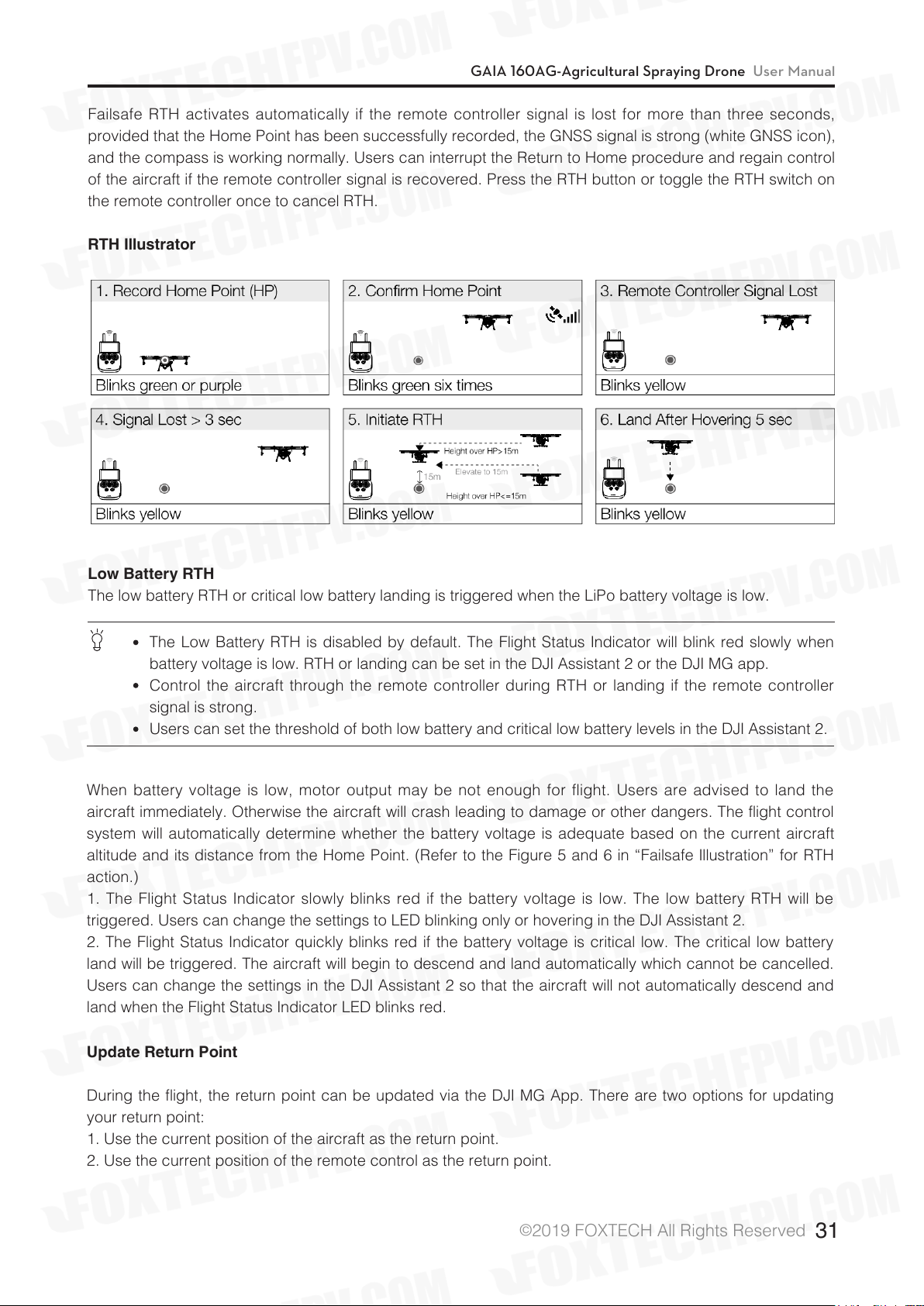
Failsafe RTH activates automatically if the remote controller signal is lost for more than three seconds,
provided that the Home Point has been successfully recorded, the GNSS signal is strong (white GNSS icon),
and the compass is working normally. Users can interrupt the Return to Home procedure and regain control
of the aircraft if the remote controller signal is recovered. Press the RTH button or toggle the RTH switch on
the remote controller once to cancel RTH.
RTH Illustrator
Low Battery RTH
The low battery RTH or critical low battery landing is triggered when the LiPo battery voltage is low.
The Low Battery RTH is disabled by default. The Flight Status Indicator will blink red slowly when
battery voltage is low. RTH or landing can be set in the DJI Assistant 2 or the DJI MG app.
Control the aircraft through the remote controller during RTH or landing if the remote controller
signal is strong.
Users can set the threshold of both low battery and critical low battery levels in the DJI Assistant 2.
When battery voltage is low, motor output may be not enough for flight. Users are advised to land the
aircraft immediately. Otherwise the aircraft will crash leading to damage or other dangers. The flight control
system will automatically determine whether the battery voltage is adequate based on the current aircraft
altitude and its distance from the Home Point. (Refer to the Figure 5 and 6 in “Failsafe Illustration” for RTH
action.)
1. The Flight Status Indicator slowly blinks red if the battery voltage is low. The low battery RTH will be
triggered. Users can change the settings to LED blinking only or hovering in the DJI Assistant 2.
2. The Flight Status Indicator quickly blinks red if the battery voltage is critical low. The critical low battery
land will be triggered. The aircraft will begin to descend and land automatically which cannot be cancelled.
Users can change the settings in the DJI Assistant 2 so that the aircraft will not automatically descend and
land when the Flight Status Indicator LED blinks red.
Update Return Point
During the flight, the return point can be updated via the DJI MG App. There are two options for updating
your return point:
1. Use the current position of the aircraft as the return point.
2. Use the current position of the remote control as the return point.
©
2019 FOXTECH All Rights Reserved
31
Page 33
GAIA 160AG-Agricultural Spraying Drone User Manual
When using the built-in GNSS module of the remote control for the relevant return point
setting function, please try to ensure that the GNSS module (the position with the DJI mark) is
unobstructed and there are no tall buildings around it.
Follow the steps below to update your return point:
1. Run DJI MG App to enter the job interface.
2. Click××× > to select “ ” in the return point setting, and the current coordinates of the aircraft will be
updated to the return point.
3. Tap ×× ×> to select “ ” in the return point setting, and the current coordinates of the remote will be
updated to the return point.
4. After the return point is set successfully, the aircraft status indicator will flash green.
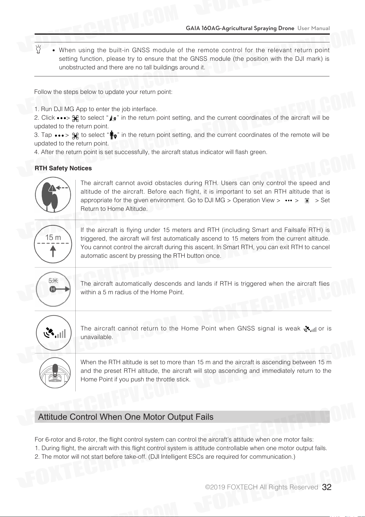
RTH Safety Notices
The aircraft cannot avoid obstacles during RTH. Users can only control the speed and
altitude of the aircraft. Before each flight, it is important to set an RTH altitude that is
appropriate for the given environment. Go to DJI MG > Operation View > > > Set
Return to Home Altitude.
If the aircraft is flying under 15 meters and RTH (including Smart and Failsafe RTH) is
triggered, the aircraft will first automatically ascend to 15 meters from the current altitude.
You cannot control the aircraft during this ascent. In Smart RTH, you can exit RTH to cancel
automatic ascent by pressing the RTH button once.
The aircraft automatically descends and lands if RTH is triggered when the aircraft flies
within a 5 m radius of the Home Point.
The aircraft cannot return to the Home Point when GNSS signal is weak or is
unavailable.
When the RTH altitude is set to more than 15 m and the aircraft is ascending between 15 m
and the preset RTH altitude, the aircraft will stop ascending and immediately return to the
Home Point if you push the throttle stick.
Attitude Control When One Motor Output Fails
For 6-rotor and 8-rotor, the flight control system can control the aircraft’s attitude when one motor fails:
1. During flight, the aircraft with this flight control system is attitude controllable when one motor output fails.
2. The motor will not start before take-off. (DJI Intelligent ESCs are required for communication.)
©
2019 FOXTECH All Rights Reserved
32
Page 34
GAIA 160AG-Agricultural Spraying Drone User Manual
Propulsion System Protection
Low voltage and overweight aircraft warnings are provided.
Altitude Stabilization System
Profile
To ensure that the spray is evenly dispensed, the aircraft uses the radar module on the Altitude Stabilization
System to maintain the same distance above the crops at all times.
Radar Module
Users can use one radar module to mount under the aircraft for a fixed height. Three radar modules can
also be installed in the front, rear and lower directions of the aircraft respectively, and the front and rear
radar modules can predict the terrain and better simulate the flight. The radar function can be turned on or
off in the app. If enabled, the fixed/predictive function is automatically enabled in the route mode, AB-point
mode and enhanced manual mode. In the manual mode, the radar module can measure the altitude, but
the aircraft cannot fly in a fixed altitude by using the measurement data.
How to Use
1. Make sure that the radar function is turned on in the App.
2. Enter the desired operation mode and set the relative crop height in the App.
3. After starting the operation, if the working conditions of the radar module are met, the aircraft will always
maintain a relative height to the crop when it is flying.
The Altitude Stabilization System will only maintain a fixed distance from vegetation within its
working range.
There are large height differences (> 1m) in vegetation (i.e. nearby ditches or ponds, above sparse
trees or shrubs, terraced fields).
Flying over inclined surfaces (depending on aircraft speed). Recommended maximum inclination
at different speeds: 15° at 1 m/s, 6° at 3 m/s and 3° at 5 m/s.
Obey local radio transmission laws and regulations.
The radar status will be prompted in the DJI MG App. Users should always pay attention to the prompt
information. If an exception occurs, please fix it in time.
High-precision radar obstacle avoidance module (optional)
Overview
The high-precision radar obstacle avoidance module uses microwave ranging technology to realize
obstacle sensing, and can adapt to harsh working environments such as dust and spray, and supports night
work. The obstacle avoidance module can sense obstacles within 30 m of the front or rear according to the
flight direction of the aircraft and display corresponding information in the DJI MG App to improve the safety
of the plant protection operation.
©
2019 FOXTECH All Rights Reserved
33
Page 35

GAIA 160AG-Agricultural Spraying Drone User Manual
The built-in stabilization gimbal ensures that the radar detection angle is not affected by the attitude change
of the aircraft, and at the same time, the front or rear obstacle detection is switched according to the front or
rear flight of the aircraft.
Use
App settings
After ensuring that the obstacle avoidance module is installed correctly, turn on the remote control and
connect the aircraft to the power supply. Go to the app's homework interface > > and make sure that the
obstacle avoidance feature is turned on.
Aircraft action
1. During the flight, if an obstacle is detected in the detection range 6 meters away from the aircraft, the
aircraft will decelerate and then hover approximately 6 meters from the obstacle.
2. During the flight, if an obstacle is detected within the detection range within 6 meters from the aircraft,
the aircraft will immediately brake to hover. The complete stopping of the aircraft requires a certain braking
distance. In this case, the user should always pay attention to the distance between the aircraft and the
obstacle. If necessary, the aircraft can be operated to fly in the opposite direction to avoid collision.
3. If the aircraft is in line operation or A-B point mode, the aircraft pauses the current task and records the
break coordinate point during deceleration. After the user manipulates the aircraft to bypass the obstacle,
the job can be resumed.
©
2019 FOXTECH All Rights Reserved
34
Page 36
GAIA 160AG-Agricultural Spraying Drone User Manual
DJIMGApp
The DJI MG app is designed for agricultural applications and is able to display the system status and
configure various settings. After planning a task via the app’s intelligent operation planning system, the
aircraft can operate automatically following the produced flight route.
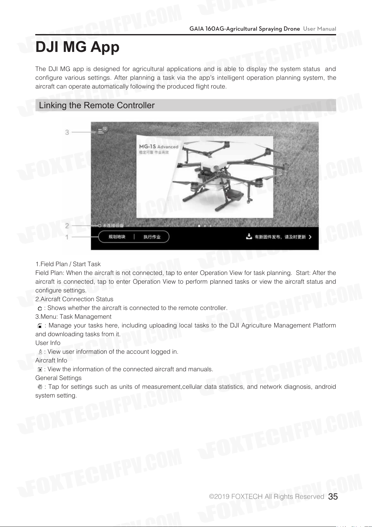
Linking the Remote Controller
1.Field Plan / Start Task
Field Plan: When the aircraft is not connected, tap to enter Operation View for task planning. Start: After the
aircraft is connected, tap to enter Operation View to perform planned tasks or view the aircraft status and
configure settings.
2.Aircraft Connection Status
: Shows whether the aircraft is connected to the remote controller.
3.Menu: Task Management
: Manage your tasks here, including uploading local tasks to the DJI Agriculture Management Platform
and downloading tasks from it.
User Info
: View user information of the account logged in.
Aircraft Info
: View the information of the connected aircraft and manuals.
General Settings
: Tap for settings such as units of measurement,cellular data statistics, and network diagnosis, android
system setting.
©
2019 FOXTECH All Rights Reserved
35
Page 37
Operation View
GAIA 160AG-Agricultural Spraying Drone User Manual
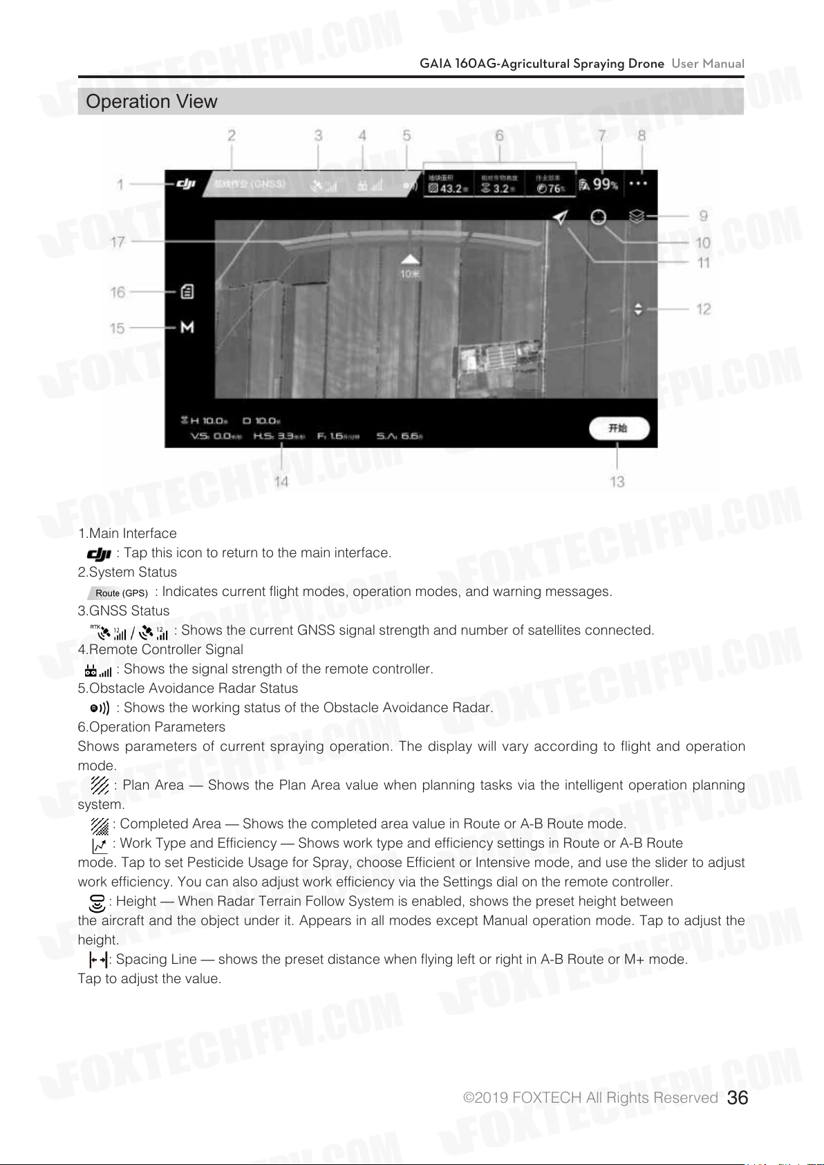
1.Main Interface
: Tap this icon to return to the main interface.
2.System Status
: Indicates current flight modes, operation modes, and warning messages.
3.GNSS Status
: Shows the current GNSS signal strength and number of satellites connected.
4.Remote Controller Signal
: Shows the signal strength of the remote controller.
5.Obstacle Avoidance Radar Status
: Shows the working status of the Obstacle Avoidance Radar.
6.Operation Parameters
Shows parameters of current spraying operation. The display will vary according to flight and operation
mode.
: Plan Area — Shows the Plan Area value when planning tasks via the intelligent operation planning
system.
: Completed Area — Shows the completed area value in Route or A-B Route mode.
: Work Type and Efficiency — Shows work type and efficiency settings in Route or A-B Route
mode. Tap to set Pesticide Usage for Spray, choose Efficient or Intensive mode, and use the slider to adjust
work efficiency. You can also adjust work efficiency via the Settings dial on the remote controller.
: Height — When Radar Terrain Follow System is enabled, shows the preset height between
the aircraft and the object under it. Appears in all modes except Manual operation mode. Tap to adjust the
height.
: Spacing Line — shows the preset distance when flying left or right in A-B Route or M+ mode.
Tap to adjust the value.
©
2019 FOXTECH All Rights Reserved
36
Page 38
GAIA 160AG-Agricultural Spraying Drone User Manual
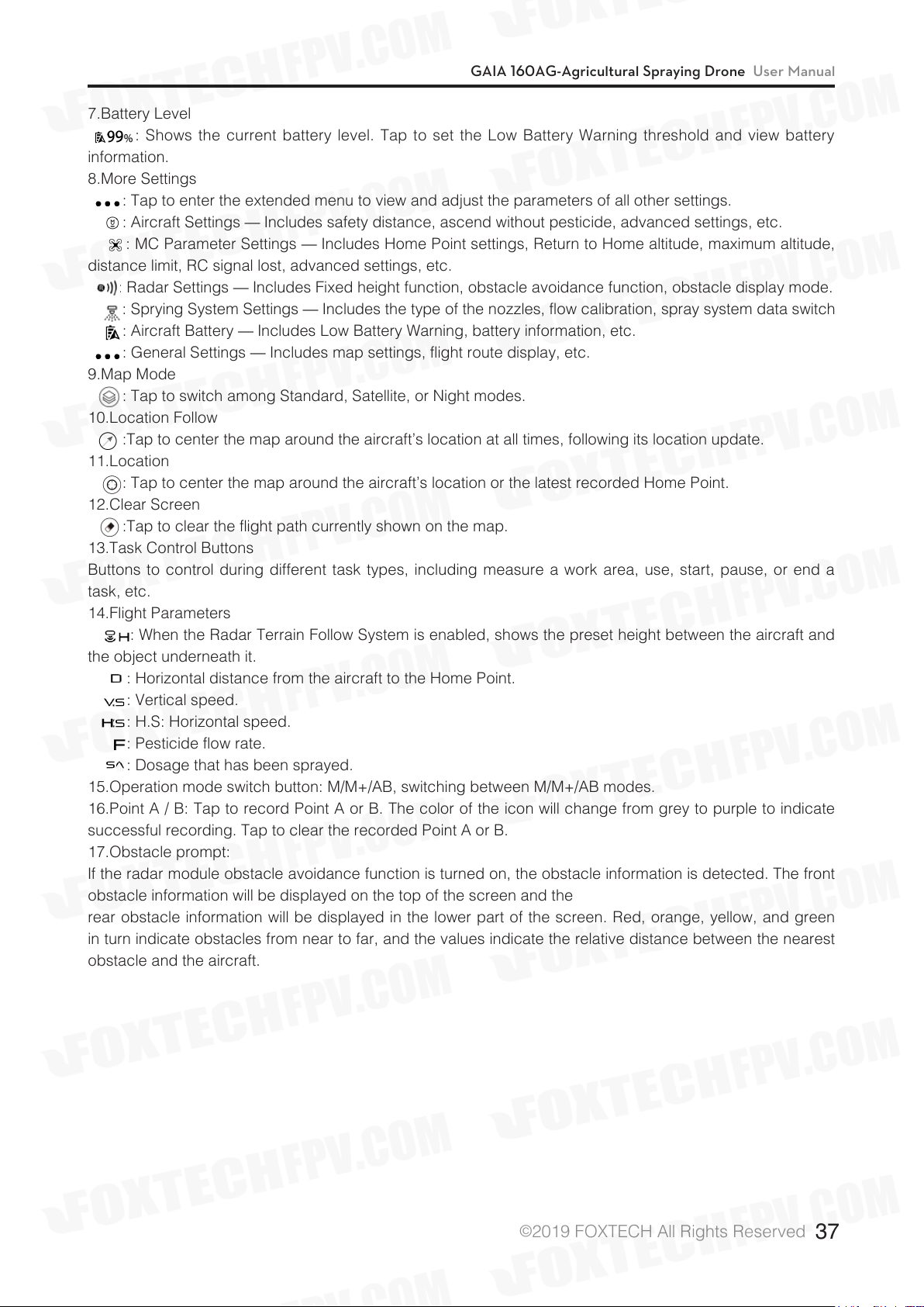
7.Battery Level
: Shows the current battery level. Tap to set the Low Battery Warning threshold and view battery
information.
8.More Settings
: Tap to enter the extended menu to view and adjust the parameters of all other settings.
: Aircraft Settings — Includes safety distance, ascend without pesticide, advanced settings, etc.
: MC Parameter Settings — Includes Home Point settings, Return to Home altitude, maximum altitude,
distance limit, RC signal lost, advanced settings, etc.
: Radar Settings — Includes Fixed height function, obstacle avoidance function, obstacle display mode.
: Sprying System Settings — Includes the type of the nozzles, flow calibration, spray system data switch
: Aircraft Battery — Includes Low Battery Warning, battery information, etc.
: General Settings — Includes map settings, flight route display, etc.
9.Map Mode
: Tap to switch among Standard, Satellite, or Night modes.
10.Location Follow
:Tap to center the map around the aircraft’s location at all times, following its location update.
11.Location
: Tap to center the map around the aircraft’s location or the latest recorded Home Point.
12.Clear Screen
:Tap to clear the flight path currently shown on the map.
13.Task Control Buttons
Buttons to control during different task types, including measure a work area, use, start, pause, or end a
task, etc.
14.Flight Parameters
: When the Radar Terrain Follow System is enabled, shows the preset height between the aircraft and
the object underneath it.
: Horizontal distance from the aircraft to the Home Point.
: Vertical speed.
: H.S: Horizontal speed.
: Pesticide flow rate.
: Dosage that has been sprayed.
15.Operation mode switch button: M/M+/AB, switching between M/M+/AB modes.
16.Point A / B: Tap to record Point A or B. The color of the icon will change from grey to purple to indicate
successful recording. Tap to clear the recorded Point A or B.
17.Obstacle prompt:
If the radar module obstacle avoidance function is turned on, the obstacle information is detected. The front
obstacle information will be displayed on the top of the screen and the
rear obstacle information will be displayed in the lower part of the screen. Red, orange, yellow, and green
in turn indicate obstacles from near to far, and the values indicate the relative distance between the nearest
obstacle and the aircraft.
©
2019 FOXTECH All Rights Reserved
37
Page 39
GAIA 160AG-Agricultural Spraying Drone User Manual
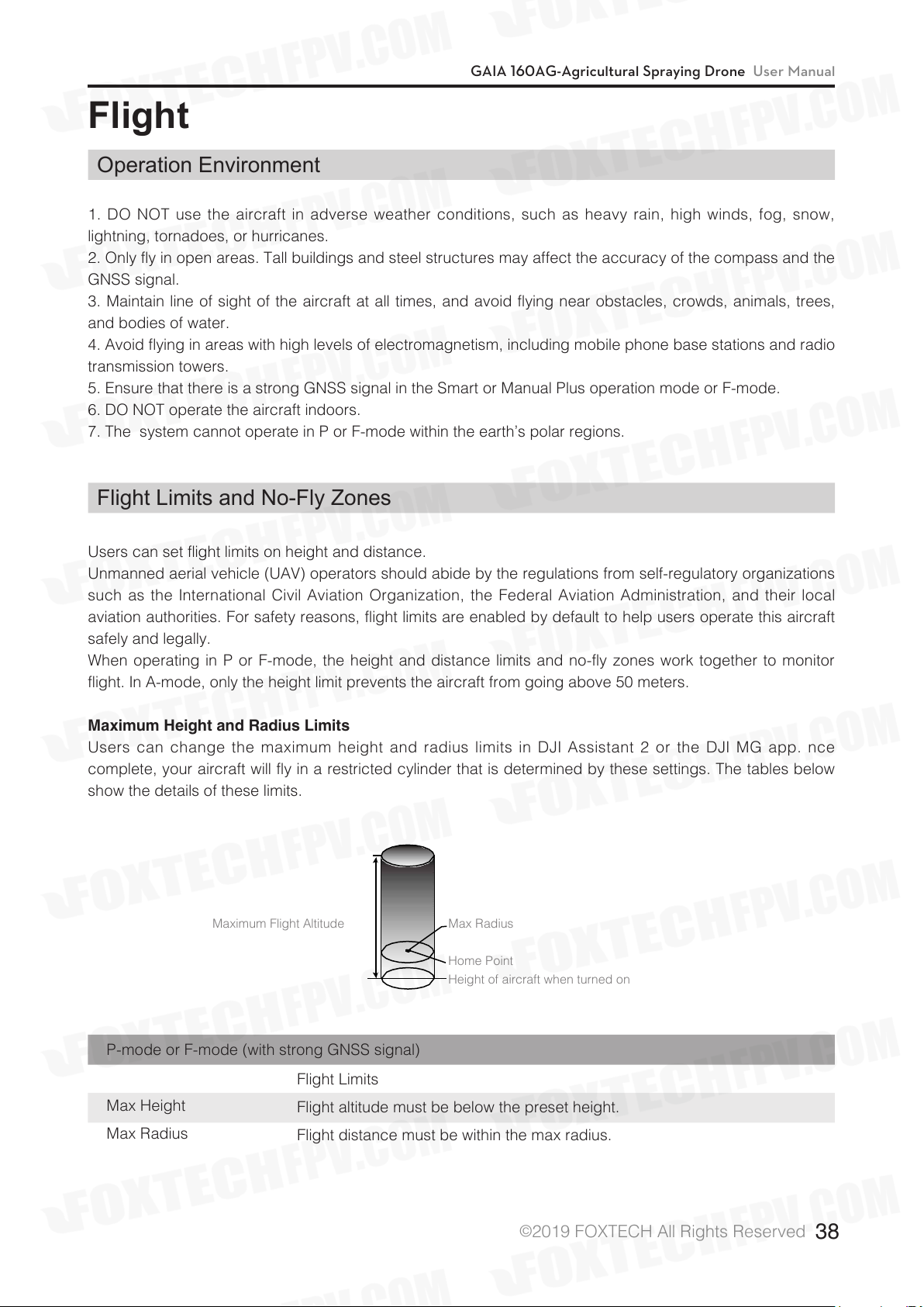
Maximum Flight Altitude
Max Radius
Home Point
Height of aircraft when turned on
Flight
Operation Environment
1. DO NOT use the aircraft in adverse weather conditions, such as heavy rain, high winds, fog, snow,
lightning, tornadoes, or hurricanes.
2. Only fly in open areas. Tall buildings and steel structures may affect the accuracy of the compass and the
GNSS signal.
3. Maintain line of sight of the aircraft at all times, and avoid flying near obstacles, crowds, animals, trees,
and bodies of water.
4. Avoid flying in areas with high levels of electromagnetism, including mobile phone base stations and radio
transmission towers.
5. Ensure that there is a strong GNSS signal in the Smart or Manual Plus operation mode or F-mode.
6. DO NOT operate the aircraft indoors.
7. The system cannot operate in P or F-mode within the earth’s polar regions.
Flight Limits and No-Fly Zones
Users can set flight limits on height and distance.
Unmanned aerial vehicle (UAV) operators should abide by the regulations from self-regulatory organizations
such as the International Civil Aviation Organization, the Federal Aviation Administration, and their local
aviation authorities. For safety reasons, flight limits are enabled by default to help users operate this aircraft
safely and legally.
When operating in P or F-mode, the height and distance limits and no-fly zones work together to monitor
flight. In A-mode, only the height limit prevents the aircraft from going above 50 meters.
Maximum Height and Radius Limits
Users can change the maximum height and radius limits in DJI Assistant 2 or the DJI MG app. nce
complete, your aircraft will fly in a restricted cylinder that is determined by these settings. The tables below
show the details of these limits.
P-mode or F-mode (with strong GNSS signal)
Max Height
Max Radius
Flight Limits
Flight altitude must be below the preset height.
Flight distance must be within the max radius.
©
2019 FOXTECH All Rights Reserved
38
Page 40
GAIA 160AG-Agricultural Spraying Drone User Manual
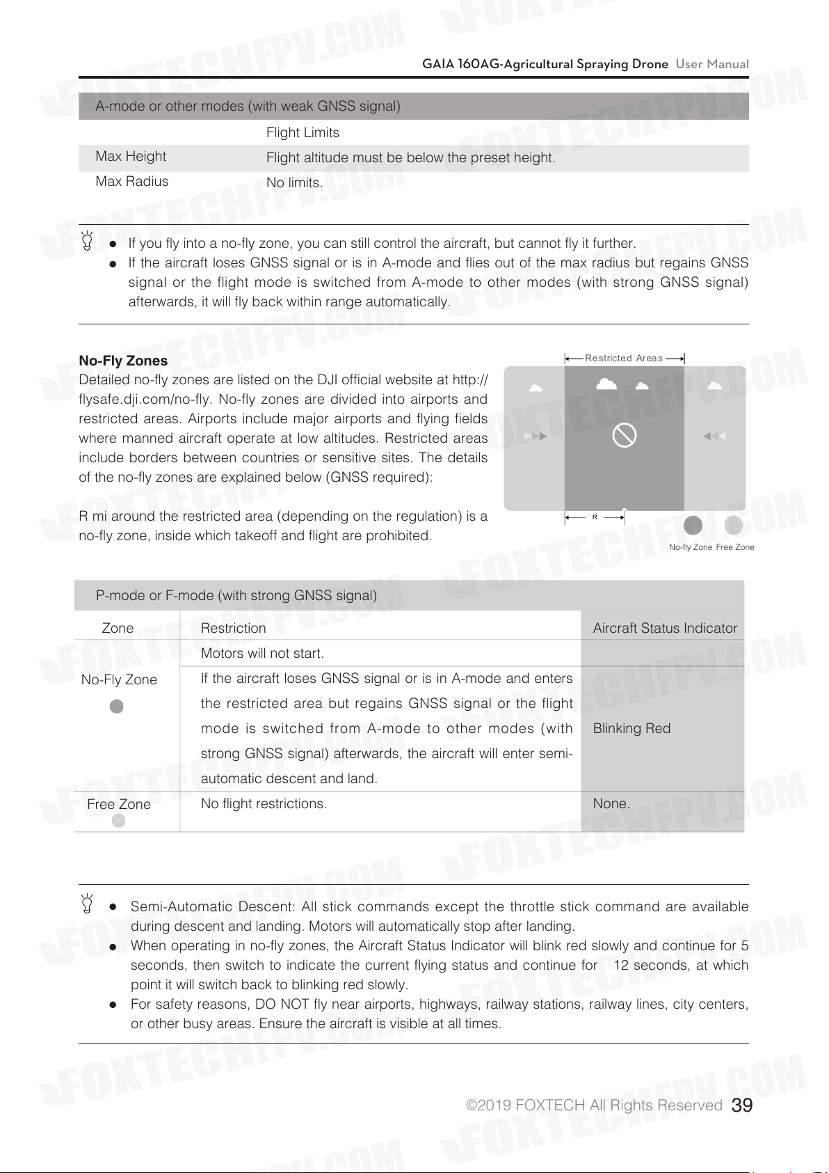
Restricted Areas
R
A-mode or other modes (with weak GNSS signal)
Flight Limits
Max Height
Max Radius
Flight altitude must be below the preset height.
No limits.
If you fly into a no-fly zone, you can still control the aircraft, but cannot fly it further.
If the aircraft loses GNSS signal or is in A-mode and flies out of the max radius but regains GNSS
signal or the flight mode is switched from A-mode to other modes (with strong GNSS signal)
afterwards, it will fly back within range automatically.
No-Fly Zones
Detailed no-fly zones are listed on the DJI official website at http://
flysafe.dji.com/no-fly. No-fly zones are divided into airports and
restricted areas. Airports include major airports and flying fields
where manned aircraft operate at low altitudes. Restricted areas
include borders between countries or sensitive sites. The details
of the no-fly zones are explained below (GNSS required):
R mi around the restricted area (depending on the regulation) is a
no-fly zone, inside which takeoff and flight are prohibited.
P-mode or F-mode (with strong GNSS signal)
Zone
Restriction
Motors will not start.
No-Fly Zone
If the aircraft loses GNSS signal or is in A-mode and enters
the restricted area but regains GNSS signal or the flight
mode is switched from A-mode to other modes (with
strong GNSS signal) afterwards, the aircraft will enter semi-
automatic descent and land.
Free Zone
No flight restrictions.
Semi-Automatic Descent: All stick commands except the throttle stick command are available
during descent and landing. Motors will automatically stop after landing.
When operating in no-fly zones, the Aircraft Status Indicator will blink red slowly and continue for 5
seconds, then switch to indicate the current flying status and continue for 12 seconds, at which
point it will switch back to blinking red slowly.
For safety reasons, DO NOT fly near airports, highways, railway stations, railway lines, city centers,
or other busy areas. Ensure the aircraft is visible at all times.
No-fly Zone Free Zone
Aircraft Status Indicator
Blinking Red
None.
©
2019 FOXTECH All Rights Reserved
39
Page 41

GAIA 160AG-Agricultural Spraying Drone User Manual
Pre-Flight Checklist
Mounting and Components Checklist
1. Ensure that all parts are mounted correctly and firmly.
2. Ensure that the ESCs and receiver are connected correctly and firmly.
3. Ensure that the spraying hoses are without any blockage.
4. Test if the nozzles work normally.
LED Status Checklist
1. Ensure that the mode switch corresponds to the flight status LED.
2. System status LEDs on the GNSS-Compass / GPS-Compass Pro are normal.
3. Ensure that all the sensor parameters are correct and the IMUs are calibrated correctly.
DJI Assistant 2 Checklist
1. Ensure that the aircraft mounting parameters are correct.
2. Ensure that the flight controller parameters are correct.
3. Low voltage level protection and Failsafe protection are set correctly.
Compass Calibration
Ensure the compass is calibrated before every flight. Failure to calibrate may lead to poor flight performance
or a crash.
1. DO NOT attempt to calibrate your compass where there is a chance of strong magnetic interference.
This includes areas where there are massive metal objects, parking structures, steel reinforcements
underground, or under bridges.
2. DO NOT carry ferromagnetic materials with you during calibration, such as keys or mobile phones.
3. The compass should always be calibrated when moving from indoor spaces to outdoor spaces.
4. After successful calibration, the compass may become abnormal when you place the aircraft on the
ground. This may be because of underground magnetic interference. Move the aircraft to another location
and try again.
Calibration Procedures
Choose an open space to carry out the following procedures.
Using the remote controller
1.Enter the App, click “perform the task”, then click on the flight status bar at the top of the screen and click
on “Calibration” in the aircraft status list. The yellow status indicator of the aircraft status indicator indicates
that the compass calibration program is activated.
2. Hold and rotate the aircraft horizontally 360 degrees, and the Flight Status Indicator will display a solid
green light.
3. Hold the aircraft vertically with nose pointing downward, and rotate it 360 degrees around the center axis.
4. The Flight Status Indicator shows the current flight mode when calibration is complete. If the Flight Status
Indicator blinks red, repeat the steps above to recalibrate the compass.
©
2019 FOXTECH All Rights Reserved
40
Page 42

GAIA 160AG-Agricultural Spraying Drone User Manual
Using DJI MG (Datalink 3 is required):
Tap the Aircraft Status Bar in the Operation View of the DJI MG app and select Calibrate in the Aircraft
Status List, then follow the on-screen instructions.
The DJI MG app will prompt you to calibrate the compass if needed. The prompts will disappear
after successful calibration.
When to Recalibrate
1. When compass data is abnormal, and the Aircraft Status Indicator is blinking red and yellow.
2. When flying in a new location, or a location that is different from your last flight.
3. When the mechanical structure of the system has changed, i.e. the mounting position of the compass has
changed.
4. When severe drifting occurs in flight, i.e. the aircraft does not fly in a straight line.
Flow Calibration
When spraying for the first time, be sure to perform flow calibration, otherwise it will seriously affect the
operation. Always use the measuring cup in the package for water injection to ensure accuracy. The entire
calibration process takes approximately 6 - 14 minutes, please be patient.
1. Preparation before calibration: Exclude pipe air (if it is excluded, flow calibration can be performed
directly)
×(1) Add approximately 2 L of water to the work box.
×(2) 2 Turn on the remote control and connect the aircraft to the power source.
×(3) Open the four pressure relief valves, short press the remote control spray button to turn on the spray
until the air in the pipe is exhausted*, then close the pressure relief valve and stop spraying.
* If the air cannot be removed for a long time, completely unscrew the pressure relief valve cover to remove
it, and drain the air before replacing the cover.
2. Flow calibration
×(1)×level gauge calibration
Add approximately 1 L of water to the pesticide tank. Go to the App's job interface, click > , and click
the “Calibrate” button on the right side of the flow.
©
2019 FOXTECH All Rights Reserved
41
Page 43
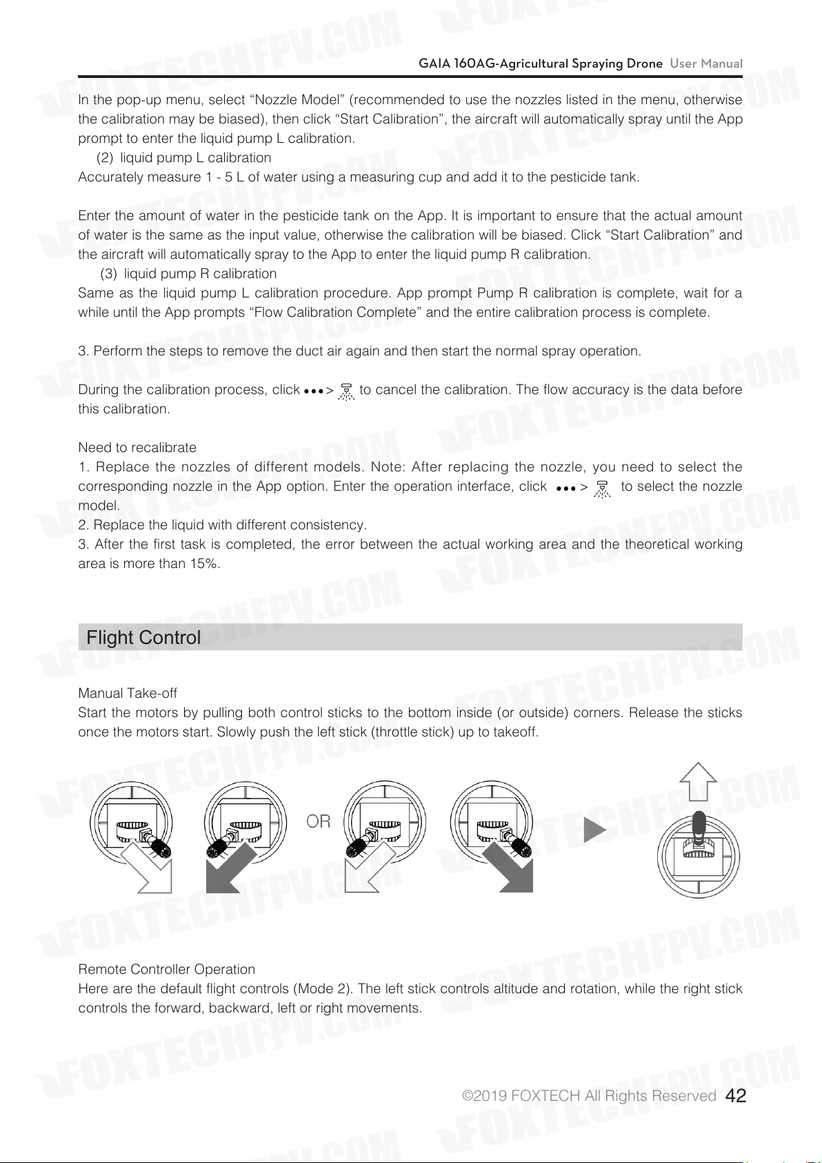
GAIA 160AG-Agricultural Spraying Drone User Manual
In the pop-up menu, select “Nozzle Model” (recommended to use the nozzles listed in the menu, otherwise
the calibration may be biased), then click “Start Calibration”, the aircraft will automatically spray until the App
prompt to enter the liquid pump L calibration.
×(2)×liquid pump L calibration
Accurately measure 1 - 5 L of water using a measuring cup and add it to the pesticide tank.
Enter the amount of water in the pesticide tank on the App. It is important to ensure that the actual amount
of water is the same as the input value, otherwise the calibration will be biased. Click “Start Calibration” and
the aircraft will automatically spray to the App to enter the liquid pump R calibration.
×(3)×liquid pump R calibration
Same as the liquid pump L calibration procedure. App prompt Pump R calibration is complete, wait for a
while until the App prompts “Flow Calibration Complete” and the entire calibration process is complete.
3. Perform the steps to remove the duct air again and then start the normal spray operation.
During the calibration process, click > to cancel the calibration. The flow accuracy is the data before
this calibration.
Need to recalibrate
1. Replace the nozzles of different models. Note: After replacing the nozzle, you need to select the
corresponding nozzle in the App option. Enter the operation interface, click > to select the nozzle
model.
2. Replace the liquid with different consistency.
3. After the first task is completed, the error between the actual working area and the theoretical working
area is more than 15%.
Flight Control
Manual Take-off
Start the motors by pulling both control sticks to the bottom inside (or outside) corners. Release the sticks
once the motors start. Slowly push the left stick (throttle stick) up to takeoff.
Remote Controller Operation
Here are the default flight controls (Mode 2). The left stick controls altitude and rotation, while the right stick
controls the forward, backward, left or right movements.
©
2019 FOXTECH All Rights Reserved
42
Page 44

GAIA 160AG-Agricultural Spraying Drone User Manual
You can customize or change these controls through the DJI MG app.
Manual Landing
Use the below method to stop the motors:
When the aircraft has landed, push the throttle down and hold. The motors
will stop after 3 seconds.
You can use the below method to stop the motors in the event of an emergency.
When the aircraft has landed, push the throttle down, then perform the CSC (Control Stick
Combination). The motors will stop immediately. Release both sticks once the motors have
stopped.
©
2019 FOXTECH All Rights Reserved
43
Page 45

GAIA 160AG-Agricultural Spraying Drone User Manual
DJIAssistant2
Configure settings of the remote controller and flying parameters, copy flight records, use the flight
simulator, and update aircraft firmware in the DJI Assistant 2.
Installation and Launching
1. Download the DJI Assistant 2 installation file from the MG-1S download page:
http://www.dji.com/agriculture-solution/info#downloads
2. Install the software.
3. Launch DJI Assistant 2.
Using DJI Assistant 2
Connect the Micro USB port of the LED module to your computer with a Micro USB cable.
Be sure to remove the propellers before using DJI Assistant 2.
Dashboard
Check all basic settings on this page. Click the blue hyperlinks for detailed settings.
Basic Settings
Airframes
Select the type of your airframe.
Mounting
Set IMU direction and GPS position. Please note the positive direction of the axis and the unit (mm).
Remote Controller
Set the type of your receiver (SBUS by default), adjust dead zone, control EXP, and calibrate the remote
controller, etc. Click “Channel” for channel mapping and test.
ESC Settings
Choose ESC type, test motors and calibrate ESC. The motor will rotate at full throttle during ESC calibration.
Make sure to remove the propellers before ESC calibration.
Flight Settings
Propulsion Configuration
Set basic gain and propulsion system bandwidth.
Gain
Set advanced gain, horizontal velocity gain and sensitivity gain.
Failsafe Settings
Select the Failsafe action of the aircraft between hover and RTH, set RTH altitude (not beyond the maximum
altitude) and the aircraft’s heading during RTH.
If not using foldable propellers, you can disable the Propeller Action in this page.
Battery
Configure the threshold and the aircraft actions of low battery warnings.
Flight Restriction
Set the maximum altitude (up to 50 m). Enable or disable distance limit and set the value (up to 8000 m).
©
2019 FOXTECH All Rights Reserved
44
Page 46

GAIA 160AG-Agricultural Spraying Drone User Manual
Agras Application
Set the Operation Interval (Line Spacing) from 3 to 10 m. It is set to 5 m by default.
Set four speed gears for Smart Operation Mode from 1 to 8 m/s. The four speed gears are set to 1, 3, 5, 7
m/s by default.
Enable or disable altitude stabilization and no-pesticide protection features in Smart, Manual Plus or Manual
Operation mode and F-mode (if using the Datalink 3).
Tools
Topology
View system status and error information. Click the flight controller icon to enter IMU calibration.
View and calibrate IMU status.
Function Channels
To map F channels in this page.
Backup
Flight controller parameters backup and recovery. Only parameters in products of the same type and
firmware can be supported for backup and recovery.
Spraying
Set PWM pulse width and frequency of F channel output to be compatible with the third party pump ESC.
Simulator
Click Open to enter flight simulation and practice flight. Click Start Simulation and aircraft attitude data (e.g.,
roll, pitch, yaw) will be shown on the right of the screen.
Firmware Update
A DJI account is required for firmware updates. Login with your DJI account or register for one.
Flight Data
You can use Data Viewer to view flight data, or enter SD card mode to copy it.
Data Viewer is used to view and analyze the flight data files of the aircraft for performance analysis and
troubleshooting.
©
2019 FOXTECH All Rights Reserved
45
Page 47

Appendix
Flight Status LED Indicator Descriptions
GAIA 160AG-Agricultural Spraying Drone User Manual
LED
Description
©
2019 FOXTECH All Rights Reserved
46
Page 48
GAIA 160AG-Agricultural Spraying Drone User Manual
FAQ
1. The flight controller cannot connect to the assistant software.
a. Please check if the driver and assistant software is installed successfully.
b. Please check if the main controller is correctly connected;
c. Please check if the main controller is powered.
d. Try replacing the Micro USB cable or the USB port on your computer.
2. How to upgrade the firmware of Flight Controller?
Use the Micro USB cable to connect the LED module of main controller to your computer and upgrade the
firmware with the DJI Assistant 2 For MG Assistant software.
3.How to adjust the sensitivity?
After connecting the LED module of main controller to the computer using the Micro USB cable, the
sensitivity is adjusted by the DJI Assistant 2 For MG Assistant software.
4.Can the DJI Datalink 3 air unit and remote controller purchased on the official website of DJI directly
replace the air unit and remote controller in this set?
No. Please use the corresponding module in this kit for replacement.
5.The water pump is not working properly. How to check it?
a. Check if the water pump switch is turned on;
b. Check if the remote controller spray button is damaged;
c. Check that the water pump ESC signal wire is properly connected and the link is complete.
6. How does the aircraft take off and roll over?
a. Check if the main controller installation orientation is correct;
b. Check if the direction of motor and the propeller rotation is correct?
c. Whether the ESC signal wire and the main controller wire are correctly corresponding;
d. Calibrate the ESC throttle stroke (third-party ESC)
7. How high is the high-speed radar obstacle avoidance module hovering from the obstacle?
a. During the flight, if an obstacle is detected in the detection range 6 meters away from the aircraft, the
aircraft will decelerate and then hover at a distance of about 6 meters from the obstacle;
b. During the flight, if an obstacle is detected within the detection range within 6 meters from the aircraft,
the aircraft will immediately brake to hover.
The complete stopping of the aircraft requires a certain braking distance. In this case, the user should
always pay attention to the distance between the aircraft and the obstacle. If necessary, the aircraft can be
operated to fly in the opposite direction to avoid collision.
8. Does it support Lightbridge HD video transmission system?
Lightbridge HD video transmission system is not supported.
9. Support the Seeding machine or not?
supported.
10.Support external third-party level meter or not?
Match with electrical level(3.3V) of level meter in this kit.
To ensure stability, it is not recommended to use a third-party level mete.
©
2019 FOXTECH All Rights Reserved
47
Page 49

GAIA 160AG-Agricultural Spraying Drone User Manual
This content is subject to change.
Download the latest version from
https://www.foxtechfpv.com/gaia-160-ag-hexacopter-arf-combo.html
For everyday updates, please follow
Foxtech Facebook page: Foxtechhobby
YouTube Channel: Foxtech
©
2019 FOXTECH All Rights Reserved
48
 Loading...