

Page 1
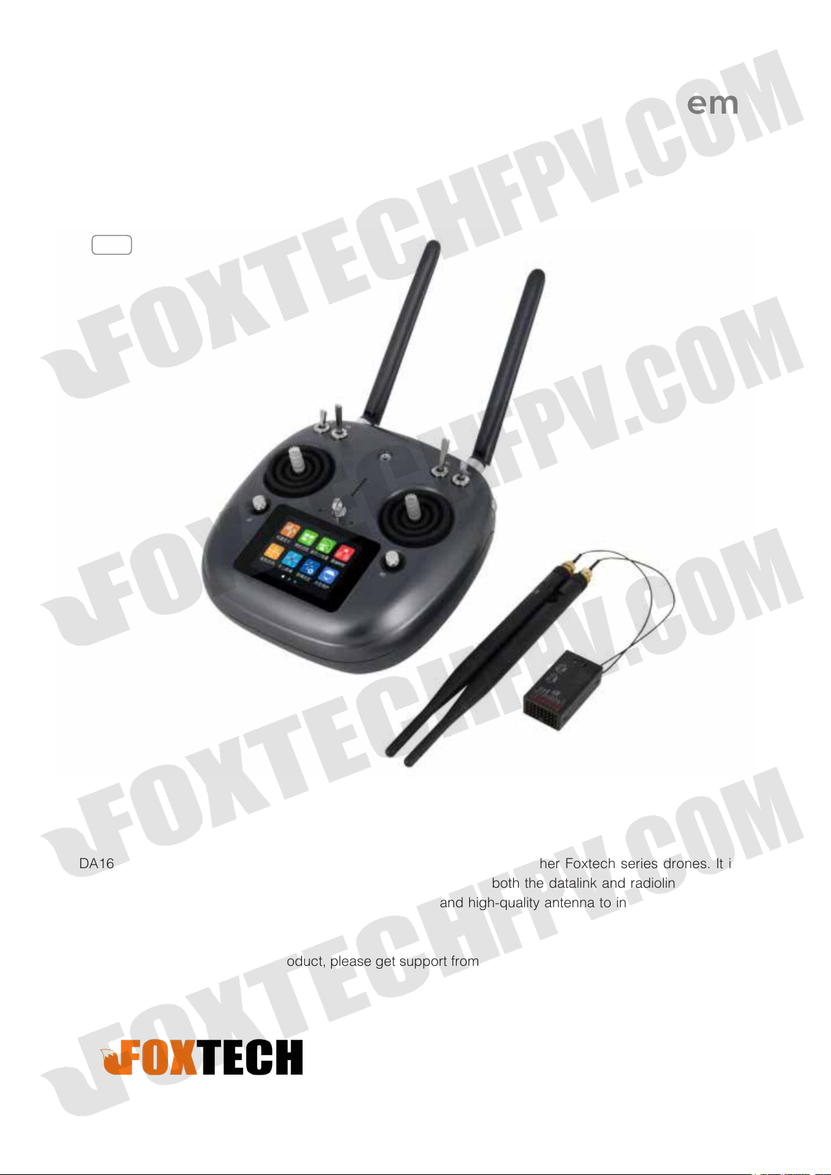
Foxtech DA16 Radio Control System
User Manual
V2.1
2018.10
DA16, specially designed for VTOL like Nimbus, and also suitable for other Foxtech series drones. It is a
16-channel radio which has datalink and radiolink built inside, so both the datalink and radiolink can reach
a range of 5km. You also could equip the range booster and high-quality antenna to increase the distance
to 15km.
If you have any issue using the product, please get support from support1@foxtechfpv.com.
Page 2
Contents
Foxtech DA16 Radio Control System User Manual
Read Tips
Icon Denition
Flight Safety
Precautions on Charging DA16 Transmitter
Precautions on Using SD Card
Precautions on Storage/Carrying/Recycling
Product Introduction
Product Features
Parts
Technical Specications
LED Indicator Denition
Get Ready to Use DA16
Get to Know Your DA16
3
3
3
4
4
4
5
5
6
8
8
9
9
Aircraft Power Battery
DA16 and Flight Controller Connection
How to Place Transmitter Antenna Right
How to Charge DA16 Transmitter
How to Link DA16 Transmitter to DA16 Receiver
Select Transmitter Throttle Joystick Type
Main Menu Introduction
Model Settings
Select Transmitter Throttle Joystick Type
Model Sel
Model Type
CH MAP
Reverse
9
10
11
12
12
13
14
15
16
16
18
20
22
2018 FOXTECH All Rights Reserved
©
1
Page 3
Foxtech DA16 Radio Control System User Manual
Trim
TrimSet
Trainer
FailSafe
Timer
LowVol Alert
System Settings
Comm Set
Screen Lock & Display
H / W Set
ExPort Stts
Stick Cali
Dial Cali
22
23
24
25
26
27
28
28
29
29
30
31
32
Export File
Receiver Settings
Comm Set
Voltage Calibrating
PWM Settings
Datalink Settings
Basic Settings
Advanced Settings
BlueCong
33
34
34
35
36
37
38
39
40
2018 FOXTECH All Rights Reserved
©
2
Page 4
Foxtech DA16 Radio Control System User Manual
Read Tips
Icon Denition
Please pay more attention to content indicated with the following marks:
DANGER Dangerous manipulation probably leads to human injuries.
WARNING Warnings on manipulation possibly leads to human injuries.
CAUTION Cautions on manipulation may lead to property loss.
Prohibited Mandatory
Flight Safety
DA16 transmitting and receiving system is designed for professional application in specific industries,
users who use the device should have at least basic ability manipulating it. Any irregular or irresponsible
manipulations of the device may cause damages and lead to property loss or human injuries. Non-adult
users must follow their trainer’s guidance oradults’ supervision. Disassembling or modification on DA16
transmitter is prohibited without a permission from Foxtech.
To maintain a safe and a good flight experience of Foxtech's product, please read the prohibited and
mandatory carefully:
Do not use DA16 transmitter to control aircraft in places of intensive crowd (squares, parks), places of
many obstructions (streets, parking lots), fields of strong magnetic or interference (power/radar stations,
railways) or any other fields that may cause property loss or human injuries.
Do not hold or cover transmitter antenna or obstruct transmission by any means in a flight.
Do not point directly to aircraft with antennas’ upper end in a flight.
Do not fly aircraft when you are tired, drunk, sickness or in any occasions that not feeling good.
Do not fly aircraft when there is a rain, strong wind or at night.
Do not power off transmitter in a flight while aircraft engine and motors are still working.
Keep aircraft within sight range in a flight.
Make sure DA16 transmitter’s screen menu is returned to system menu before taking off a flight, in case
of any accidents caused by mistouching system settings.
Do not forget to check transmitter and receiver battery level before flying an aircraft.
Power off aircraft first, then transmitter, when a flight is over.
Before doing any settings or adjustment on transmitter, make sure aircraft engine is powered off and
motor wires are off connection, in case of switching on accidentally.
Before fly aircraft for the first time, make sure that the Fail-safe function preprogrammed in DA16
transmitter is activated.
Before fly aircraft for the first time, power on transmitter first and hold throttle joystick at its bottom
position, then power on aircraft.
2018 FOXTECH All Rights Reserved
©
3
Page 5
Foxtech DA16 Radio Control System User Manual
Precautions on Charging DA16 Transmitter
DA16 transmitter is equipped with a built-in Li-Po 1S rechargeable battery, compatible with standard USB
chargers (5V/2A output) in market.
Considering there are many different types of chargers, please read the prohibited and mandatory carefully
before charging DA16 transmitter.
Do not use USB chargers over 5V output to charge DA16 transmitter.
Make sure DA16 transmitter is powered off before charging, charging current should not exceed 2A.
Stop charging if you find charger damaged, broken or overheated.
Stop charging if you sense a peculiar smell, smoke or leak.
Do not charge DA16 transmitter when the temperature is over 60 degree centigrade.
Keep it away from places that a baby or a kid may reach while you are charging DA16 transmitter,
and better if there is supervision in case of accidents.
Precautions on Using SD Card
Do not disassemble, bend, press, abandon or damage SD card by any means.
Stop using the SD card if you find it soaked by water, oil or other chemical liquid.
SD card is also an electronic product, keep it from static electricity.
Micro-SD card slot clean in case of blocking by sand or dirt.
Keep SD card in slot while you are downloading or uploading data; taking it out mistakenly,
hitting or shattering it may cause damage or data loss.
Keep SD card away from places that a baby or a kid may reach in case of swallowing mistakenly.
Precautions on Storage/Carrying/Recycling
Keep DA16 transmitter away from places that a baby or a kid may reach when you are placing or
storing it.
Please avoid placing or storing DA16 transmitter at places below:
Places are extremely hot (above 60℃) or cold (under 20℃);
Places with direct sunshine, too dusty or wet;
Places with an unstable structure or may cause vibration;
Places near steam or other heat sources.
2018 FOXTECH All Rights Reserved
©
4
Page 6
Foxtech DA16 Radio Control System User Manual
Product Introduction
Product Features
Advanced SHTT Spread-spectrum Technology
DA16 transmitting and receiving system applies latest bidirectional 2.4GHz spread-spectrum technology
named as SHTT, the maximum effective transmission distance with stable flight control can be 3km
(unobstructed, free of interference). Transmitter and receiver are linked by a unique matching code,
enhancing their anti-interference performance beyond and among transmitters, allowing multiple transmitters
working in stability synchronously.
Extraordinary Handling & Accurate Manipulating Experience
DA16 transmitter fits user’s palm perfectly by applying a fashionably streamlined and compact industrial
design, a delicate ergonomics design and even a thoughtful matte silicone pad as additional protection. All
these ideas and results enable you to free your mind before taking off a flight.
16-Channel Multi-functional Fast-response Mode
DA16 transmitter’s 16 channels support all kinds of model aircrafts including Air Plane, Multirotors, Multi
Model * 5ms fast-response mode
5KM Super Long Distance Data Transmission, Real-Time Telemetry
In an unobstructed, free of interference environment, DA16's transmission distance can reach 5 kilometers,
which perfectly meets agricultural drone pilots' operating requirement on BVR (BeyondVisual Range) flights.
In DA16 transmitter monitor it displays real-time telemetry of receiver voltage, aircraft power, transmission
strength, GPS module and other multi-sensors.
Voice Broadcast with Vibration Alert
Voice broadcast with vibration alert help users be more concentrate on flight.
High Brightness Colorful LCD Touch Screen, Brand New GUI System
DA16 transmitter’s high brightness colorful screen is clearly visible in sunlight. There are no complicated
traditional keys and buttons, but a built-in LCD touch screen on transmitter,assisted by a turntable menu in
the brand new GUI system. All these revolutionary new features in software and hardware provide a more
user-friendly experience on transmitting settings.
Creative 5-dimensional Sub-trim Button
Sub-trim button designs in traditional transmitters have been overturned in DA16, now you are able to do
quick adjustment between sub-trim buttons and joysticks in a flight. The sub-trim buttons are made of metal
feeling materials, along with the unity industrial design, bring you an extraordinary manipulating experience.
Fulfils the Requirement of Complicated Models or Robots
In default, DA16 transmitter can save 64 sets of model data, the amount can be extendedwithout a limit if
necessary.
Powerful programmable mixing control supports various customized linear mixing and curve mixing.
Adjustable rate, editable throttle curve and pitch curve make complicate control easy to finish.
Data copy function provides convenience for users on sharing transmitter settings with friends.
Trainer mode support two transmitters working together, one for trainer, another for trainee. In trainer
mode there are various protection, for instance trainer transmitter can take control of flight from trainee
transmitter through one switch.
2018 FOXTECH All Rights Reserved
©
5
Page 7
Foxtech DA16 Radio Control System User Manual
Channel mapping function supports customize channel definition; Fail-safe function provides more
security to flight safety.
Built-in High Capacity Li-Po Battery
DA16 transmitter is equipped with a high capacity Li-Po 1S rechargeable battery, reliable and easy to
maintain. Through standard Micro-USB port you can charge DA16 transmitter, and it continuously works for
more than 12 hours after one time charging. You’ll never have to worry about long-time flight in outdoor.
SD Card Data Saving and Extending
DA16 transmitter supports saving flight data in SD card and extending to new functions from SD card.
Adjust Transmitter Settings and Upgrade Firmware on PC
DA16 transmitter supports adjusting system settings and upgrading firmware through PC software. It’s an
obviously promotion on user experience, and Foxtech promises to offer continuous service on updating
firmware and other cool features.
Parts
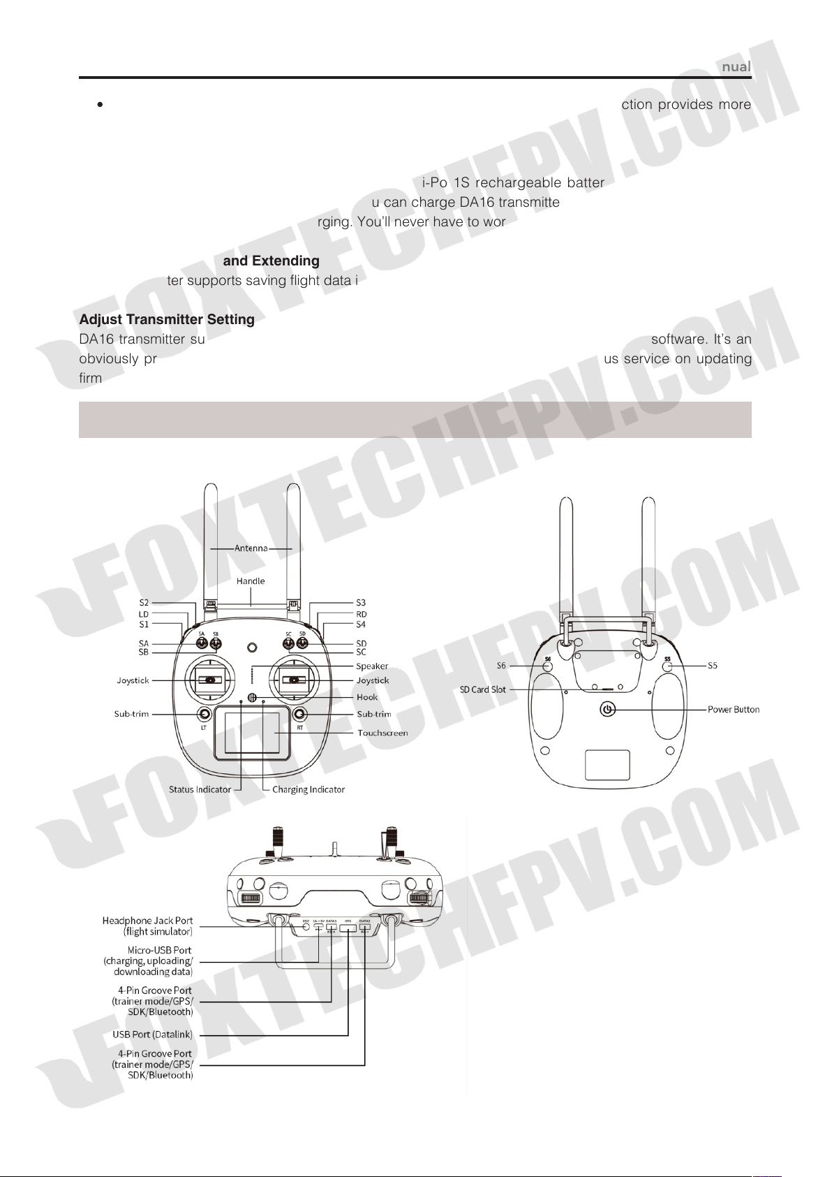
1. At a Glance
2018 FOXTECH All Rights Reserved
©
6
Page 8
Foxtech DA16 Radio Control System User Manual
2. Button/Switch Types
Name Type
SA 3 Positions; Alternate; Short Lever
SB 3 Positions; Alternate; Long Lever
SC 3 Positions; Alternate; Long Lever
SD 3 Positions; Alternate; Short Lever
LD Self-centering Dial
RD Thumb-slide Dial
Self-locking button stays in the position you press them to; Self-return button rebound to original
position after a press.
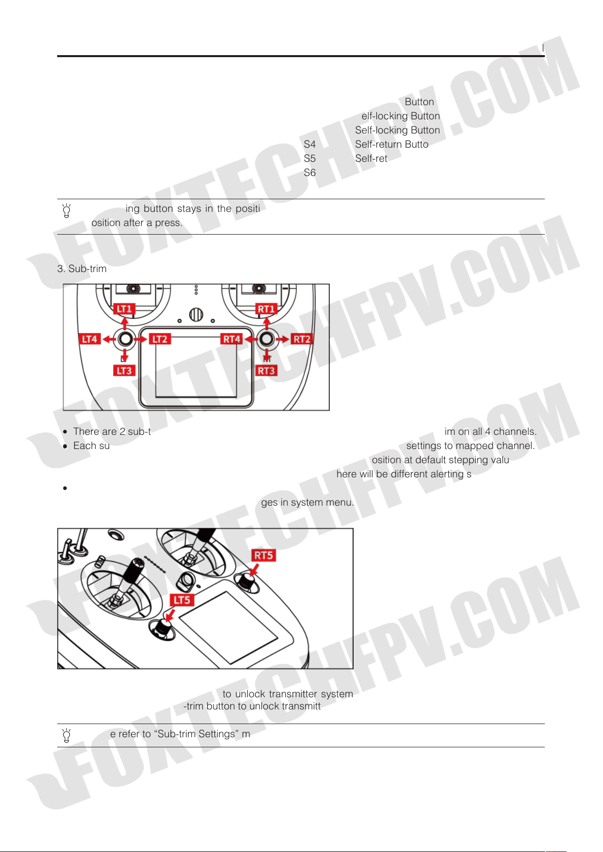
3. Sub-trim Button (This function is shut off in default setting.)
Name Type
S1 Self-return Button
S2 Self-locking Button
S3 Self-locking Button
S4 Self-return Button
S5 Self-return Button
S6 Self-return Button
There are 2 sub-trim buttons on DA16 transmitter, which support continuous sub-trim on all 4 channels.
Each sub-trim button has 2 dimensions (up-down, left-right) for direct trim settings to mapped channel.
Every push on sub-trim button leads to a movement from former position at default stepping value. Keep
pushing on sub-trim button will speed up the movement. There will be different alerting sound when subtrim button is in neutral position.
Sub-trim position shows as dynamic changes in system menu.
Sub-trim buttons can also be used to unlock transmitter system menu when transmitter lock is activated.
Press and hold left/right sub-trim button to unlock transmitter.
Please refer to “Sub-trim Settings” menu to adjusting settings of Sub-trim button.
2018 FOXTECH All Rights Reserved
©
7
Page 9

Technical Specications
Foxtech DA16 Radio Control System User Manual
Channels
Applicable Model
Data Memory
Language Display
Joystick Resolution
Frequency Band
Transmitting Power
Receiving Sensibility
Transmission Distance
PC Software
Display Screen
Display Resolution
Screen Type
Battery Type
Working Current
Duration
26 Physical Channels,16 Receiver Output Channels
Fixed Wings/Helicopters/Gliders/ Quadcopters / Multi-rotors /
Vehicles / Boat / Robots
64 Sets of Transmitter Setting Data; Extensible
Chinese/English
4096 Grades
2.4000GHz -2.4830GHz
27dBm
-101dBm
Maximum 5000 Meters(Unobstructed, Free of Interference)
Foxtech Assistant
2.8 Inch High Brightness Colorful LCD Screen
240x320
Capacitive Touch Screen
Built-in 3.7V 3000mAh Li-Po 1S Battery
270mA
12 Hours
Charging Port
Product Dimension
Product Weight
Micro-USB Port
194.5x172.5x114mm
610g
LED Indicator Denition
On DA16 transmitter, above touch screen there are two LED indicators. The left one is status indicator,the
right one is charging indicator.
Status Indicator:
Charging Indicator:
Status Indicator Definition
Solid Red: RF transmitting is off.
Solid Green: RF transmitting is on.
displays transmitter’s RF transmitting status.
displays transmitter’s charging status.
Charging Indicator Definition
Solid Red: Transmitter in charging.
Solid Green:Charging finished.
2018 FOXTECH All Rights Reserved
©
8
Page 10
Foxtech DA16 Radio Control System User Manual
Get Ready to Use DA16
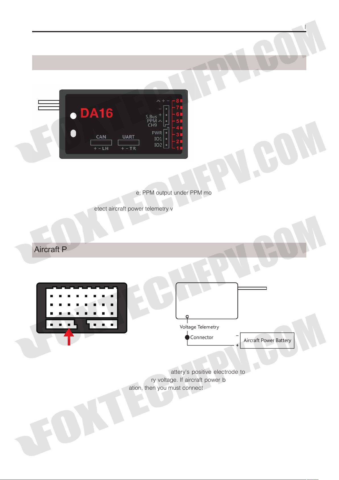
Get to Know Your DA16
Pin 1-8: PWM output for channel 1-8.
Pin 9: Channel 9 output under PWM mode; PPM output under PPM mode; SBUS output under SBUS mode.
Pin 10: Extending ports.
Pin POW: Single pin to detect aircraft power telemetry voltage. Voltage detecting range: 1-12S LiPo.
Aircraft Power Battery
Please follow the legend to connect aircraft power battery's positive electrode to sky station's POW pin,
sky station starts to return aircraft power battery voltage. If aircraft power battery doesn't share a common
ground with flight controller and sky station, then you must connect power battery negative electrode to any
pin on sky station.
2018 FOXTECH All Rights Reserved
©
9
Page 11
Foxtech DA16 Radio Control System User Manual
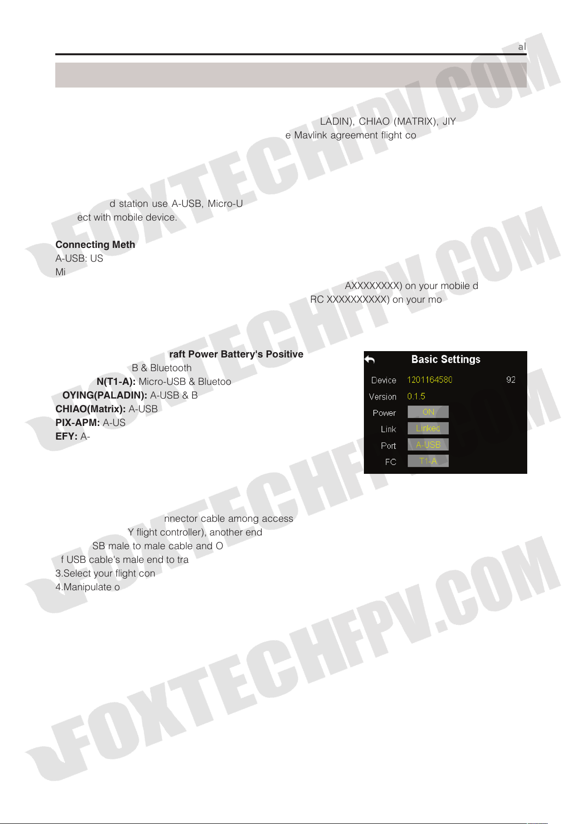
DA16 and Flight Controller Connection
UART Port Flight Controllers
TOPXGUN (T1-A), WOOZOOM (THEONE-A), BOYING (PALADIN), CHIAO (MATRIX), JIYI (K3-A),CFUAS
(C1-A) and other flight controllers under open source Mavlink agreement flight controllers such as PIX and
APM.
CAN Port Flight Controllers
EFY (FINIX200M)
DA16 ground station use A-USB, Micro-USB, Bluetooth (Optional) and WIFI (EFY flight controller only) to
connect with mobile device.
Connecting Methods
A-USB: USB Male to Male Cable + OTG Cable
Micro-USB: USB Cable + OTG Cable
Bluetooth: Search DA16 ground station bluetooth name (Default: 0AXXXXXXXX) on your mobile device.
WIFI: Search DA16 ground station wifi name (Default: EFY-RC XXXXXXXXXX) on your mobile device.
Connect This Pin to Aircraft Power Battery's Positive Electrode
JIYI(K3-A):
TOPXGUN(T1-A):
BOYING(PALADIN):
CHIAO(Matrix):
PIX-APM:
EFY:
Note: Bluetooth and WIFI are optional module,
neither of them is included in DA16's standard set.
Steps to Connect:
1.Find flight controller connector cable among accessories, connect its datalink end to air end’s UART port
(CAN port for EFY flight controller), another end to flight controller's datalink port;
2.Find USB male to male cable and OTG mobile device connector cable among accessories, connect one
of USB cable's male end to transmitter's USB port, another end to OTG cable's female end;
3.Select your flight controller and its connecting method on DA16 ground station;
4.Manipulate on mobile device to confirm connection.
A-USB & Bluetooth
Micro-USB & Bluetooth
A-USB & Bluetooth
A-USB & Bluetooth
A-USB & Bluetooth
A-USB & WIFI
2018 FOXTECH All Rights Reserved
©
10
Page 12
Foxtech DA16 Radio Control System User Manual
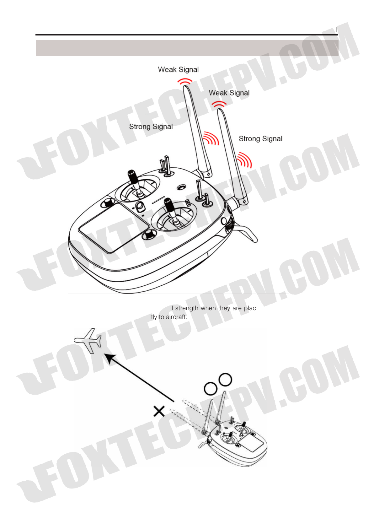
How to Place Transmitter Antenna Right
DA16 transmitter antennas have the best signal strength when they are placed horizontally. Thus, please
avoid pointing antennas’ upper end directly to aircraft.
2018 FOXTECH All Rights Reserved
©
11
Page 13

Foxtech DA16 Radio Control System User Manual
Do not fold or cover antennas and avoid any obstruction between transmitter and aircraft in a flight,
otherwise there will be an obvious decrease to transmission signal strength.
How to Charge DA16 Transmitter
Before charging DA16 transmitter, please read the part “READ TIPS - Precautions on Charging DA16
Transmitter” in this manual carefully.
Transmitter charging time is limited by charger’ power output. More power charger adapter has, less
charging time it is.
Steps to Charge DA16 Transmitter
(1) Choose the right charger for DA16 transmitter;
(2) Make sure that DA16 transmitter is powered off.
(3) Find a Micro-USB cable among accessories
coming with DA16 transmitter packaging, connect
its Micro-USB end to transmitter’s Micro-USB port on
the back, USB end toadapter charger;
(4) Plug charger into adapted AC power outlet;
(5) In charging, transmitter charging indicator is solid
red; charging finished, it turns to solid green.
DA16 transmitter is equipped with a built-in 3000mAh Li-Po 1S battery. Charging time is generally
between 2.5 to 3 hours using a standard 5V/2A adapter charger. Charging time may be different using
charger with different standards, please pay an attention to transmitter charging indicator in charging.
How to Link DA16 Transmitter to DA16 Receiver
Each unit of DA16 transmitter is assigned with a unique ID code. Before linking DA16 receiver to DA16
transmitter, receiver must identify transmitter ID(Linking). After the first linking between transmitter and
receiver, the ID code will be memorized in receiver, so that you don’t have to repeat linking next time (except
if the transmitter was linked with a different receiver after that).
Steps to Link
(1) Keep the distance between DA16 transmitter and DA16
receiver within about 1 meter, then power on transmitter;
(2) In DA16 transmitter screen menu, tap on “System Settings –
General Settings”;
(3) On DA16 receiver, stick a pin or needle into receiver’s linking
hole, press and hold linking button for 3 seconds till receiver
status indicator blinks red quickly. Receiver now is ready for
linking;
2018 FOXTECH All Rights Reserved
©
12
Page 14

Foxtech DA16 Radio Control System User Manual
(4) In transmitter “Comm Set” menu, tap on “Bind” button, and
wait for 1 second, when both transmitter status indicator and
receiver indicator blink green, linking steps are done.
Before linking transmitter to receiver, make sure aircraft engine is powered off and motor wires are off
connection.
Reboot receiver when linking steps are done, and try to manipulate on transmitter to confirm if linking
is successful.
Select Transmitter Throttle Joystick Type
DA16 transmitter’s throttle joystick has two types, Thumb-slide and self-centering joystick. Users can select
throttle joystick type according to their preferences.
Thumb-slide Joystick:
joystick is not in its bottom position, and disables RF transmitting automatically (transmitter status indicator is
off). Transmitter will not enable RF transmitting until throttle joystick was back in bottom position.
Self-centering Joystick:
Step to Select Transmitter Joystick Type
In transmitter “System Settings” menu, tap on “Comm Set”, then tap on “Thr – Thumb-slide / Self-centering”
to select your favorite type.
While users are powering on transmitter, it alerts with voice broadcast if throttle
No alert, transmitter works normally.
2018 FOXTECH All Rights Reserved
©
13
Page 15

Foxtech DA16 Radio Control System User Manual
Main Menu Introduction
Model Name
Model Type
Battery Level
Settings
Receiver Voltage
Aircraft Voltage
Sub-trim
: Displays maximum two timers to assist users with their flights.
Timer
: Displays your current model after selecting a set of model data.
: Displays your current model type after choosing one.
: Displays DA16 transmitter’s current remaining battery level.
: Tap on the icon to enter “Transmitter Settings” menu.
: Displays receiver’s current power voltage telemetry.
: Displays aircraft’s current power voltage telemetry.
: Displays digital sub-trim value of all 4 channels.
2018 FOXTECH All Rights Reserved
©
14
Page 16

Foxtech DA16 Radio Control System User Manual
Model Settings
In DA16 transmitter’s “Model Settings” menu there are a series of transmitter functions, offering basic and
advanced settings for different kind of model devices.
General Functions
Monitor
Model Sel
Model Type
EPA
CH MAP
Reverse
Trim
TrimSet
Trainer
Timer
Low Vol Alert
(Channel Monitor): Display real-time output value of all channels.
: Select / Save a set of model data.
: Choose the requiring model type for aircraft.
: Set each channel’s output value and the maximum / minimum limit.
(Channel Mapping): Set / Change each channel’s function.
(Channel Reverse): Reverse a channel’s output direction.
: Do trim adjustment on aircraft’s flight attitude.
: Adjust sub-trim function’s stepping value.
: Allows trainers teach their trainees on transmitter.
: Turn on / off timer function.
(Low Voltage Alert): Aircraft low battery alert.
2018 FOXTECH All Rights Reserved
©
15
Page 17

Foxtech DA16 Radio Control System User Manual
Select Transmitter Throttle Joystick Type
Through servo monitor, users can check output value changing of all 16 channels in real-time after their
customized settings on transmitter.
Model Sel
In Model Select function, users can select, rename, copy
and reset model data.
1. Select a Model
In DA16 transmitter’s model list there are maximum 64 sets of model data for your selection.
Steps to Select a Model
(1) In “Model Sel” menu, tap on “Model Sel” icon to enter model select menu;
2018 FOXTECH All Rights Reserved
©
16
Page 18

Foxtech DA16 Radio Control System User Manual
(2) Tap on your requiring model, then “Select”, in screen menu it pops up “Confirm your selection” menu,
tap on “YES” to finish selecting.
2. Rename a Model
Users can rename model data in model list to differ them from various purposes. Your currently selected
model datais displayed in transmitter main menu.
Steps to Rename a Model
(1) Tap on your requiring model, then “Rename”, in screen menu it pops up “Confirm to rename the model”;
then “Yes”, in screen it shows a virtual keyboard menu;
(2) Input a new name for the model using virtual keyboard, then tap on “yes” to finish.
3. Copy a Model
Users can copy model data from transmitter’s model list for backup, by doing so, you just need to revise
requiring data instead of inputting all data when you adjust settings for a new model.
Steps to Copy a Model
(1) Tap on your requiring model, then
“Copy”, in screen it shows “Copying Model”
menu;
2018 FOXTECH All Rights Reserved
©
17
Page 19

Foxtech DA16 Radio Control System User Manual
(2) Select a target model through turntable, then tap on “Yes” to finish copying.
4. Reset all Models
Users can reset former model data in model list, after resetting, the model recovers to default settings.
Steps to Reset a Model
(1) Tap on your requiring model, then “RES”, in screen menu it pops up “Confirm to reset the model” dialog;
(2) Tap on “Yes” to finish resetting.
Model Type
In DA16 transmitter there are several default model types, Airplane, Multirotors and Multi Model, each model
type with necessary settings done in advance.Users need to select your requiring model and do advanced
settings.
2018 FOXTECH All Rights Reserved
©
18
Page 20

Foxtech DA16 Radio Control System User Manual
When you select a requiring model type, all data in current model will be reset automatically.
It’s better to save model data through model select function before switching to another model type.
Steps to Select a Model Type
(1) In “transmitter settings” menu, tap on “Model Settings”, then “Model Type”;
(2) In screen, first it displays the current model type; tap on the model icon, screen menu is switched to “Model
Type” menu;
(3) Tap on your requiring model type; select your requiring type and tap on “Apply” to finish.
2018 FOXTECH All Rights Reserved
©
19
Page 21

Foxtech DA16 Radio Control System User Manual
CH MAP
DA16 transmitter’s all 16 channels can be mapped randomly to joysticks, switches, buttons and dials on
transmitter.
Steps to Map Channels
(1) In model settings menu, tap on “CH MAP”, in screen it shows channel mapping menu;
(2) In DA16 transmitter, Channel 1-4 are default to functions such as aileron, elevator, throttle and rudder;
(3) Take an example of channel 1 (aileron), tap on “SB”,in screen it shows transmitter channel list;
(4) Select your requiring joysticks, switches, buttons or dials from channel list;
(5) Tap on “Return” to finish channel mapping.
In channel mapping menu, if you need to redefine a channel, tap on the channel name, in screen it
shows transmitter channel definition list; select a definition from the list to finish redefining channel.
2018 FOXTECH All Rights Reserved
©
20
Page 22

Foxtech DA16 Radio Control System User Manual
In channel mapping menu, tap on “Reset” to rest all channel data.
DA16 Transmitter’s Channel Definition Introduction
Sub-Trim Mapping
When channel mapping is finished, users can set digital sub-trim mapping according to their preference.
Digital sub-trim channel definition is default to Up-Down (LT1-LT3, RT1-RT3) and Left-Right (LT2-LT4, RT2RT4).
Steps to Set Sub-trim Mapping
When channel mapping is done, tap on the blank option next to your requiring channel, select your target
sub-trim direction to finish settings.
Sub-trim mapping can be repeatedly used in different channels; sub-trim mapping data is reset
together with channel mapping data, please make backup in advance.
2018 FOXTECH All Rights Reserved
©
21
Page 23

Foxtech DA16 Radio Control System User Manual
Reverse
Reverse function helps users reverse a channel’s direction.
Steps to Set Servo Reverse
(1) When DA16 transmitter is linked to a new model, please confirm if all servos are mapping to the right
channels first;
(2) Try to manipulate transmitter’s joysticks, switches, buttons and dials to confirm if each channel direction
is normal or reverse;
(3) In model setting menu, tap on “Servo Reverse”, in screen it shows servo reverse menu;
(4) In servo reverse menu, select your requiring channel, tap on “Normal” to turn it to “Reverse”, it means
that the channel has been reversed.
Trim
Trim function helps users set channel’s middle position and do trim adjustment to aircraft’s flight attitude.
Before Trim settings, please make sure that the target sub-trim channel is in middle position.
We do not suggest using Trim function when you are flying agricultural drones.
2018 FOXTECH All Rights Reserved
©
22
Page 24

Foxtech DA16 Radio Control System User Manual
Steps to Adjust Trim
(1) In model select menu, tap on “Trim”, in screen it shows Trim menu;
(2) Tap on your requiring channel; use turntable to select a target middle value;
(3) Repeat step 2 if you need to adjust other channels.
In Trim menu, tap on “Reset” on upper right corner in screen to reset all settings.
TrimSet
TrimSet helps users adjust digital sub-trim’s stepping value.
Equivalence relationship between trim setting value and trim stepping value are,
5 Trim Setting Value =1 Trim Stepping Value
That is, when trim setting value changes in 5, trim stepping value changes in DA16 transmitter’s trim setting
value is default to be 5, trim setting value’s minimum limit is 0, maximum limit is 100; trim stepping value’s
minimum limit is 0, maximum limit is 20.
Steps to Adjust TrimSet
(1) In model settings menu, tap on “TrimSet”, in screen it shows TrimSet menu;
(2) Through TrimSet function, users are able to adjust all 4 sub-trim channels; tap on your requiring to
change its trim stepping value;
(3) Use virtual turntable to select your target trim stepping value, adjustable range is from 0 to 100;
2018 FOXTECH All Rights Reserved
©
23
Page 25

Foxtech DA16 Radio Control System User Manual
(4) Tap on “Return” to finish setting.
In TrimSet menu, tap on “Reset” on upper right corner in screen to reset all settings.
Trainer
DA16 transmitter’s trainer mode helps experienced users train new talents. In trainer mode, two transmitters
are connected with a trainer cable. Users decide which channel to do training.
In trainer mode, DA16 transmitter supports turning on/off the function through a physical switch or button.
And users can switch identity between trainer and student.
Steps to Use Trainer Mode
(1) Use trainer cable to connect trainer transmitter’s DATA1 port with student transmitter’s DATA1 port;
(2) In model settings menu, tap on “Trainer”, in screen it shows trainer mode menu;
(3) In trainer mode menu it showsa list of all 16 channels; tap on “ON/OFF” to turn on/off the function;
2018 FOXTECH All Rights Reserved
©
24
Page 26

Foxtech DA16 Radio Control System User Manual
(4) The transmitter with trainer mode turned on is master transmitter, the other one is slave transmitter; in
master transmitter the channel is default to be “Trainer”;
(5) Each channel in the list has two status, trainer and student; when in master transmitter you change the
status to “Student”, slave transmitter gets authority to manipulate the channel, otherwise it has no authority;
(6) In trainer mode menu, you can define a physical switch or button to turn on / off the function; tap on
“NULL”, in screen menu it pops up “Choose a switch / button”; follow the hint to manipulate a switch /
button, in screen it shows switch status menu; tap on every icon to define the switch / button;
7.When definition is done, the physical switch / button takes control of turning on / off trainer mode.
FailSafe
Before linking DA16 transmitter to DA16 receiver, receiver has to be input fail safe program to turn on fail
safe function.Thus if in some moments there’s no signal transmission between transmitter and receiver,
receiver runs on the program immediately to protect the aircraft from crash in flight.
Step to Set Fail Safe
(1) In model settings menu, tap on “Fail Safe”, in screen it shows fail safe menu;
(2) In fail safe menu, the function is default to be off and in every channel it displays “HOLD”; in default
status, if transmitter lost signal from receiver, receiver outputs the last group of channel values from
transmitter;
2018 FOXTECH All Rights Reserved
©
25
Page 27

Foxtech DA16 Radio Control System User Manual
(3) Tap on “OFF” down left in screen to switch it to “ON”,fail safe function starts working;
(4) While fail safe function is working, tap on your requiring channel and switch “HOLD” to “0”; use virtual
turntable to input channel value;
(5) You can also input channel value by manipulate a joystick, switch, button, or dial which is mapped to the
channel; when it reaches to your target value, tap on “SET” to confirm;
(6) Users can still use virtual turntable to make final adjustment on channel value in case the value input
from physical switches is not accurate.
For flight safety, users must set and turn on fail safe function before a flight.
Timer
In DA16 transmitter main menu it displays two timers, users can use both if necessary.
Timing Mode
Up: Counts from 0, timer alerts when it reaches setting time.
Down: Counts from setting time, timer alerts when it gets back to 0.
Define a Timing Switch
Start: Define a switch / button for “Start”.
Stop: Define a switch / button for “Stop”.
Reset: Define a switch / button for “Reset”.
2018 FOXTECH All Rights Reserved
©
26
Page 28

LowVol Alert
Foxtech DA16 Radio Control System User Manual
DA16 transmitter’s power telemetry function helps users set voltage alert. When aircraft’s power voltage is
lower than a safe level, users receive voice and vibration alert from transmitter.
Steps to Set LowVol Alert
(1) In model settings menu, tap on “LowVol Alert”, in screen it shows voltage alert menu;
(2) Tap on power voltage, then “+/-” to adjust voltage value;
(3) Tap on “Return” to finish.
2018 FOXTECH All Rights Reserved
©
27
Page 29

System Settings
Functions
Foxtech DA16 Radio Control System User Manual
Comm Set
Lock&Display
H/W Set
settings.
Export File
Stick Cali
Dial Cali
(Common Settings): Set transmitter’s basic functions.
(Hardware Settings): Change several transmitter channels’ hardware definition through software
(Extending Ports Settings): Set transmitter extending ports’ definition.
(Joystick Calibrating): Calibrate transmitter joysticks.
(LD Calibrating): Calibrate transmitter left dial LD.
Comm Set
(Screen Lock & Display): Turn on / off transmitter touch screen display, adjust brightness.
2018 FOXTECH All Rights Reserved
©
28
Page 30

Foxtech DA16 Radio Control System User Manual
General Settings Menu Introduction
: Start linking DA16 transmitter to DA16 receiver.
Bind
. (Language): SwitchDA16 transmitter’s system language between Chinese/English.
Lang
(Throttle Type): Switch throttle joystick type between “Self-centering” and “Thumb-slide”.
THR
(Joystick Mode): Switch joystick mode from American Hand/Japanese Hand/Chinese Hand/Custom
Joy
Hand.
(Vibration): Turn on/off transmitter’s vibration alert function.
VIB
Sound
Tx-Alarm
transmitter will alert.
RF Status
RDStep
channel value the channel value increases in every movement.
(Voice Broadcast): Turn on/off transmitter’s voice broadcast function.
(Transmitter Low Battery Level Alert): Set a transmitter battery level limit lower than which
(Transmitting Status): Turn on/ off radio signal transmitting.
(RD Stepping Value): Set transmitter right dial’s stepping value (range: 1-100). Higher it is, more
Screen Lock & Display
Users can turn on / off DA16 transmitter’s screen lock, setting screen lock waiting time, adjust screen
brightness and screen sleep waiting time.
Screen Lock and Display Introduction
Screen Lock
Screen Lock Waiting Time
Screen Brightness
Screen Sleeping Time
automatically after waiting time) and set waiting time. When you set it “Never”, transmitter screen stays on.
When screen lock is enabled, press down a sub-trim button (LT5 direction of left sub-trim button, RT5
direction of right sub-trim button) for 3 seconds to unlock the screen.
: Users can do nothing touching on screen menu when screen lock is enabled.
: Set waiting time before locking transmitter screen.
: Adjust screen brightness (range 1 - 20).
: Turn on / off transmitter screen’s sleeping function (screen display turns off
H / W Set
2018 FOXTECH All Rights Reserved
©
29
Page 31

Foxtech DA16 Radio Control System User Manual
H/W Set help users do advanced settings for DA16 transmitter’s LD dial (switch between Position / Speed
Mode) and S1 / S4 / S5 / S6 switches (switch between Self-locking / Self-return).
The Difference between LD Dial’s Position and Speed Mode
Position Mode
channel value output increases.
Speed Mode
value output increases. Speed mode is usually used among aerial photography users to change gimbal
camera angle.
Steps to Set LD Dial
(1) In system settings menu, tap on “H / W Settings”, in screen it shows H / W settings menu;
(2) Tap on “Position / Speed” to switch LD’s working mode; in speed mode, you can tap on “+ / -” to
increase or decrease LD’s stepping value to change LD’s rotating speed.
How to Set S1 / S4 / S5 / S6 Switches
In H / W settings menu, select your requiring switch, tap on “Self-locking / Self-return” to switch its working
mode.
: LD channel value output depends on dial’s position. More dial angle changes, more
: LD channel value output depends on dial’s rotating speed. Faster dial rotates, more channel
ExPort Stts
DA16 transmitter’s extending ports help users extend transmitter function to external hardware devices and
SDK. Currently DA16 transmitter supports Micro-USB, USB and 4-Pin Groove Port (DATA1 / DATA 2).
DA16 Transmitter Ports Function Assignment
Micro-USB: Charging, parameter adjustment, firmware upgrading and datalink output.
USB: Datalink output (only available for DA16 transmitter datalink version)
DATA1/DATA2: Firmware upgrading of DA16 receiver series, trainer mode and SDK.
Steps to Set DATA1 / DATA 2 Port
(1) In system settings menu, tap on “ExPort Stts”, in screen it shows extending ports settings menu;
(2) Select DATA1 / DATA 2 to switch function assignment (Transmitter / Receiver / GPS / SDK);
(3) In “Transmitter” mode, DATA1 / DATA2 is assigned for trainer mode, trainer
(4) Transmitter output and trainee transmitter input;
(5) In “Receiver” mode, DATA1 / DATA2 is assigned for upgrading DA16 receiver series firmware (for details
please refer to DA16 Receiver User Manual);
2018 FOXTECH All Rights Reserved
©
30
Page 32

Foxtech DA16 Radio Control System User Manual
(6) In “GPS” mode, DATA1 / DATA2 is assigned for GPS module. By extending to GPS module, farming
drone users can handle DA16 transmitter to mark flight points in farmland;
(7) In “SDK” mode, DATA1 / DATA2 is assigned for outputting joystick channel value, users can tap on “+ / -”
to increase or decrease output frequency.
Field
STX
Data Length
CMD ID
DATA
Check Sum
SDK Agreement Format
Stick Cali
Index
0
2
5
6
38
Bytes
1
1
1
32
1
Description
0X55
Data field byte length value: 32
0x00
Joystick channel data
Data type: 16-byte unsigned int for channel 1-16
8 bytes (check sum from 0 byte to 37 byte)
Stick Cali function help users calibrate joysticks’ middle position. Regularly calibrating joysticks help users
maintain joysticks’ control accuracy. Only the self-centering joysticks require calibrating. They require
calibrating when they fail to reach their maximum / minimum positions or stay out of their middle position
(channel output value is not 0).
Steps to Calibrate
(1) In system settings menu, tap on “Stick Cali”, in screen it shows joystick calibrating menu;
(2) The cross coordinate system displays joysticks’ real-time position;
(3) Tap on “Start Calibrating”, in screen it pops up “Confirm if all joysticks are in middle position”;
2018 FOXTECH All Rights Reserved
©
31
Page 33

Foxtech DA16 Radio Control System User Manual
(4) Hold joysticks and main them in middle position (joystick’s tick mark aligns with transmitter’s tick mark),
then tap on “Next”;
(5) Transmitter starts detecting joysticks’ middle position automatically, do not move joysticks while you are
waiting;
(6) When detecting is finished, push both joysticks to their maximum positions, moving and circling them for
several times;
(7) Tap on “Finish Calibrating” to finish.
Dial Cali
Dial Cali function helps users maintain LD dial’s output accuracy. LD dial requires calibrating when it stays
out of its middle position (channel output value is not 0) or fail to reach its maximum / minimum position.
Steps to Calibrating LD
(1) In system settings menu, tap on “LD Calibrating”, in screen it shows LD calibrating menu;
(2) Tap on “Start Calibrating”, in screen menu it shows “Please confirm if LD is in its middle position”;
(3) Make sure LD is in its middle position, then tap on “Next”; in screen menu it shows “Calibrating LD’s
middle position, do not move LD”;
(4) Please do not touch LD until in screen it shows “move LD to its maximum and minimum position”; follow
the hint and repeat several times;
(5) Tap on “Finish Calibrating” when it is over.
2018 FOXTECH All Rights Reserved
©
32
Page 34

Foxtech DA16 Radio Control System User Manual
Export File
Export File function helps user export DA16 transmitter’s system settings, model settings data to SD card,
sharing the settings to other DA16 transmitters.
Steps to Export Setting Data
(1) Insert SD card to DA16 transmitter (ignore this step if it was already there);
(2) In system settings menu, tap on “Export File”, in screen it show export setting data menu;
(3) Tap on “Sys config” to export transmitter’s system setting data; “All Model” to export all model setting
data saved in transmitter; if you just need to export the current model’s setting data, tap on “Our Model”;
(4) In screen it pops up “Confirm to export” dialog, tap on “Confirm” to finish exporting.
Steps to Import Setting Data
(1) Connect DA16 transmitter to computer via USB cable, and open the software;
(2) Import your requiring setting data saved in SD card to computer through SD card reader, find files in
format “.CFG”. System setting data is name as “SYS.CFG”, all model setting data is name as “ALL.CFG”;
current model setting data is name as “MODEL+number.CFG”;
(3) In the software, tap on “Upgrade”; in “Setting Files”, tap on “Select File” to load setting files;
(4) Tap on “Upgrade” to finish.
2018 FOXTECH All Rights Reserved
©
33
Page 35

Receiver Settings
Functions
Foxtech DA16 Radio Control System User Manual
Comm Set
Volt Cali
PWM Set
: Set DA16 receiver’s basic functions.
(Voltage Calibrating): Calibrate receiver voltage telemetry.
: Change channel definition under PWM mode.
Comm Set
2018 FOXTECH All Rights Reserved
©
34
Page 36

Foxtech DA16 Radio Control System User Manual
1. Signal Mode
Set signal mode for DA16 receiver’s 3 different output mode, SBUS, PPM and PWM.
Steps to Set Signal Mode
(1) In general settings menu, select “Sigl Mode” and tap on “SBUS / PPM / PWM” to switch different signal
mode;
(2) Receiver status indicator blinks yellow once when it is switched to SBUS mode, yellow twice to PPM
mode, yellow 3 times to PWM mode;
(3) When it is done, receiver status indicator blinks green in all modes, and its blinking speed indicates
signal strength. Faster it blinks, weaker signal strength is.
2. Auto Bind
When DA16 receiver is powered on, the automatic linking function is turned on, and receives no signal from
transmitter in 20 seconds, receiver starts linking to transmitter automatically.
Automatic linking function is to simplify procedure. We suggest users to turn on the function when receiver is
installed in aircraft body, thus they have no approach to receiver’s linking button.
Do not turn on automatic linking when you are using more than one pair of transmitter and receiver at
the same time.
3. Remote Control Relay
Remote control relay function helps users with long distance flight relay. It supports two transmitters at most.
How to Use Remote Control Relay Function
(1) Prepare two DA16 transmitters, mark them with 1 and 2;
(2) Please link transmitter 1 to receiver first, then turn on “Remote Control Relay” in “General Settings Relay”
menu; transmitter 1 is the slave transmitter;
(3) Then link transmitter 2 to receiver; transmitter is always the master transmitter even if you restart receiver
or transmitter.
Voltage Calibrating
Before using DA16 receiver, we suggest users to manually calibrate receiver telemetry voltage and aircraft
power telemetry voltage once.
Here are some preparing work before calibrating.
Power on receiver and transmitter;
Link receiver to transmitter.
2018 FOXTECH All Rights Reserved
©
35
Page 37

Foxtech DA16 Radio Control System User Manual
Steps to Calibrate Receiver Telemetry Voltage (RX)
(1) Power on receiver through any PWM port, voltage range is from 3.6V to 10V, measuring with a multi-
meter;
(2) Let’s take an example of 6.0V; select “Standard Voltage” in RX menu, tap on “+/-” to set standard
voltage to 6.0V;
(3) Tap on “SET”, in screen it pops up “Calibrating Succeed”, receiver telemetry voltage calibrating is
finished.
Steps to Calibrate Aircraft Power Telemetry Voltage (POW)
(1) Power on receiver through POW port, voltage range is from 3.3V to 50V, measuring with a multi-meter;
(2) Let’s take an example of 25V; select “Standard Voltage” in POW menu, tap on “+/-” to set standard
voltage to 25V;
(3) Tap on “SET”, in screen it pops up “Calibrating Succeed”, aircraft power telemetry voltage calibrating is
finished.
PWM Settings
In DA16 transmitter users can redefine DA16 receiver’s output channel in PWM mode (Channel 1-9 in
default), so that if receiver’s channel 9 is already working in SBUS or PPM mode, PWM ports 1 to 8 can still
be defined to output transmitter channels 1 to 16.
Steps to Set PWM
(1) Power on transmitter and receiver, make sure that they are linked with each other;
(2) Transmitter PWM port 1 is mapping to receiver channel 1 PWM port, transmitter PWM port 2 is mapping
to receiver channel 2 PWM port…and so on;
(3) In “PWM Settings” menu, tap on a PWM port, select your requiring channel through virtual turntable in
screen;
(4) Tap on “SET” to finish.
2018 FOXTECH All Rights Reserved
©
36
Page 38

Foxtech DA16 Radio Control System User Manual
Datalink Settings
(For DA16 Datalink Version)
Datalink settings function requires Foxtech 2.4GHz or 915MHz datalink, please make sure that you’ve
bought DA16 transmitter datalink version. Before setting datalink, please read datalink air end’s user manual
carefully.
Functions
Basic Set
Advance Set
BlueConfig
(Basic Settings): Set datalink module’s basic functions.
(Advanced Settings): Set auto link function and baud rate.
: Choose the Bluetooth module for your flight controller.
2018 FOXTECH All Rights Reserved
©
37
Page 39

Foxtech DA16 Radio Control System User Manual
Basic Settings
Functions
Device
Version
Power
Linking
Port
output and Bluetooth output.
Flight Controller
TOPXGUN(T1-A), WOOZOOM(THEONE-A), EFY(FINIX200M),
BOYING(PALADIN), CHIAO(MATRIX), JIYI(K3-A), PIX, APM, CFUAS(C1-A) and other flight controllers under
open source Mavlink agreement flight controllers such as PIX and APM.
: Displays datalink device serial number.
: Datalink firmware version.
: Turn on / off datalink ground station.
: Link datalink ground station with datalink air end.
: Select a transmitter output way to smartphone or tablet. Available ports: A-USB output, Micro-USB
: Select a flight controller. DA16 supports all major flight controllers in market such as
Steps to Set Datalink
(1) In “Datalink Set” menu, tap on “Power” to turn on / off datalink ground station;
(2) Connect datalink air end to flight controller, power on flight controller to power datalink air end; then
press down “linking” button on datalink air end, its status indicator blinks red quickly;
(3) Return to “Datalink Settings” menu, tap on “Linking”, datalink ground “Start Linking”;
(4) Tap on “Flight Controller” menu, in screen it shows a list of all flight controllers, select your requiring flight
controller.
Before connecting transmitter’s Micro-USB port to smartphone or tablet for communication with flight
controller, you need to switch Micro-USB port settings to Datalink Mode.
2018 FOXTECH All Rights Reserved
©
38
Page 40

Foxtech DA16 Radio Control System User Manual
Steps to Switch Transmitter Micro-USB Port Mode
In “System Settings” menu, tap on “Port Settings”; tap on “Micro-USB” to switch port mode from “Parameter”
to “Datalink”.
When you switch Micro-USB port mode to “Datalink”, transmitter can no longer communicate with
computer through the port. If you need communication with computer for firmware upgrading, please
switch it back to “Parameter”.
Advanced Settings
Automatic Linking
When datalink air end is powered on, the automatic linking function is turned on, and receives no signal from
datalink ground station in 20 seconds, datalink air end starts linking to ground station automatically.
Automatic linking function is to simplify procedure. We suggest users to turn on the function when datalink
air end is installed in aircraft body, thus they have no approach to air end’s linking button.
Do not turn on automatic linking when you are using more than one pair of datalink air end and
ground station at the same time.
Baud Rate
In “Basic Set”, if your requiring flight controller type was not there in list, you can set a baud rate to match
your flight controller.
Steps to Set Baud Rate
Make sure that datalink air end is linked with ground station; in “Datalink Settings – Advanced Settings”
menu, select “Baud Rate”, tap on your requiring baud rate to finish.
2018 FOXTECH All Rights Reserved
©
39
Page 41

Foxtech DA16 Radio Control System User Manual
BlueCong
Before connecting transmitter to datalink ground station, please select the right external Bluetooth device
according to your requiring flight controller.
Bormal
Select this device for using any flight controllers except Topxgun ones.
Topxgun
Select this device for Topxgun flight controller.
This content is subject to change.
Download the latest version from
https://www.foxtechfpv.com/foxtech-da16-16-channel-radio-controller.html
For everyday updates, please follow
Foxtech Facebook page: Foxtechhobby
YouTube Channel: Foxtech
2018 FOXTECH All Rights Reserved
©
40
 Loading...